EP0248331A2 - Apparatus for determining mode of operation of film transport mechanism in camera - Google Patents
Apparatus for determining mode of operation of film transport mechanism in camera Download PDFInfo
- Publication number
- EP0248331A2 EP0248331A2 EP87107648A EP87107648A EP0248331A2 EP 0248331 A2 EP0248331 A2 EP 0248331A2 EP 87107648 A EP87107648 A EP 87107648A EP 87107648 A EP87107648 A EP 87107648A EP 0248331 A2 EP0248331 A2 EP 0248331A2
- Authority
- EP
- European Patent Office
- Prior art keywords
- spool
- film
- filmstrip
- take
- transport mechanism
- Prior art date
- Legal status (The legal status is an assumption and is not a legal conclusion. Google has not performed a legal analysis and makes no representation as to the accuracy of the status listed.)
- Granted
Links
Images


Classifications
-
- G—PHYSICS
- G03—PHOTOGRAPHY; CINEMATOGRAPHY; ANALOGOUS TECHNIQUES USING WAVES OTHER THAN OPTICAL WAVES; ELECTROGRAPHY; HOLOGRAPHY
- G03B—APPARATUS OR ARRANGEMENTS FOR TAKING PHOTOGRAPHS OR FOR PROJECTING OR VIEWING THEM; APPARATUS OR ARRANGEMENTS EMPLOYING ANALOGOUS TECHNIQUES USING WAVES OTHER THAN OPTICAL WAVES; ACCESSORIES THEREFOR
- G03B17/00—Details of cameras or camera bodies; Accessories therefor
- G03B17/42—Interlocking between shutter operation and advance of film or change of plate or cut-film
- G03B17/425—Interlocking between shutter operation and advance of film or change of plate or cut-film motor drive cameras
Definitions
- the invention relates generally to the field of photographic cameras and in particular to those cameras in which a filmstrip is first prewound from a cartridge onto a take-up spool without exposing any of the frames on the filmstrip and then is rewound one frame at a time back into the cartridge after each exposure is completed.
- a motorized film transport mechanism In operation, a leading end portion of the filmstrip extending from a light-tight cartridge loaded in the camera is attached automatically to a take-up spool.
- the take-up spool is rotated after each exposure is completed to advance successive frames of the filmstrip from the cartridge across the focal plane of a taking lens and onto the take-up spool.
- an unexposed frame on the filmstrip is located in the focal plane of the taking lens and an exposed frame is wound onto the take-up spool.
- a trailing end portion of the filmstrip remains attached to a supply spool inside the cartridge.
- This end of film condition is signalled by a sudden increase in the film tension and in the motor current as the take-up spool attempts to withdraw the remainder of the filmstrip from the cartridge.
- a tension sensing mechanism responds to the increase in film tension, or a detecting circuit responds to the increase in motor current, by reversing the motor drive to rotate the supply spool inside the cartridge. The rotated spool draws the exposed filmstrip off the take-up spool and rewinds it into the cartridge. Then, a rear door of the camera is opened and the cartridge is removed in order to process the filmstrip.
- selection of either a load (prewind) mode or an expose (rewind) mode of operation of the motorized film transport mechanism may be accomplished manually, as disclosed in U.S. Patent No. 4,251,148, granted February 17, 1981, or automatically, as disclosed in U.S. Patent Nos. 4,460,256, granted July 17, 1984, 4,504,131, granted March 12, 1985, and 4,586,801, granted May 6, 1986.
- the mode determining means suffers the disadvantage that it is mechanically complex and, therefore, is expensive to implement in a camera.
- a switch for sensing that a cartridge is present in the camera and that a rear door is closed cooperate with a tension sensing mechanism and a mode change-over member to release the member to effect a change-over from the load mode to the expose mode in response to a sudden increase in the film tension produced by the end of prewinding of the filmstrip onto a take-up spool.
- the filmstrip may be tensioned because of a snag before the filmstrip is wound onto the take-up spool, in which instance the expose mode would be introduced prematurely.
- the invention provides an improved apparatus for determining the mode of operation of a motorized film transport mechanism in an expose on rewind type camera.
- a camera having a motorized film transport mechanism which is operable in a load mode after a light-tight cartridge containing an unexposed filmstrip is loaded into the camera and is operable in an expose mode for picture-taking.
- the transport mechanism In the load mode, the transport mechanism first prewinds substantially the entire length of the filmstrip from the cartridge onto a take-up spool without exposing any of the frames on the filmstrip and then rewinds a predetermined length of the filmstrip off the take-up spool to position the first frame for exposure.
- the transport mechanism In the expose mode, the transport mechanism rewinds the filmstrip one frame at a time back into the cartridge after each exposure is completed.
- a film-on-spool sensing device When a shutter release member is actuated, a film-on-spool sensing device cooperates with a bi-directional control circuit to operate the transport mechanism in its load mode in response to sensing that the take-up spool is empty and to operate the transport mechanism in its expose mode in response to sensing that film is present on the take-up spool.
- the film-on-spool sensing device determines the mode of operation of the transport mechanism by sensing whether or not film is present on the take-up spool as a pre-condition to selecting either the load mode or the expose mode when the shutter release member is actuated.
- the invention is disclosed as being embodied preferably in a 35 mm camera. Because the features of this type camera are well known, the description which follows is directed in particular to photographic elements forming part of or cooperating directly with the disclosed embodiment. It is understood, however, that other elements not specifically shown or described may take various forms known to persons of ordinary skill in the art.
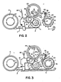
- FIG. 1 there is shown certain elements of a 35 mm camera of the type in which substantially the entire length of a filmstrip F is pre-wound from a light-tight film cartridge C onto a take-up spool or drum 1 before any exposures are taken at an aperture 3. Then, after each exposure at the aperature 3, the filmstrip F is rewound one frame at a time back into the cartridge C. This is done to protect the exposed frames on the filmstrip F in the event a rear door 5 of the camera is accidentally or inadvertently opened prematurely, i.e., before the filmstrip is rewound completely into the cartridge.
- a coaxial shaft 7 connects a metering sprocket 9 and a metering gear 11 to enable the sprocket and the gear to rotate in unison.
- the metering sprocket 9 engages successive perforations P in the filmstrip F as the filmstrip is pre-wound onto the take-up spool 1 and is rewound back into the cartridge C.
- the metering gear 11 continuously engages a counter gear 13 which is rotatably mounted atop a swing plate 15.
- the swing plate 15 is supported on the shaft 7, beneath the metering gear 11, for pivotal movement about the shaft without disengaging the counter gear 13 from the metering gear.
- a motion-transmitting stud 17 is coaxially fixed atop the counter gear 13 and has a single recess 19 for receiving successive peripheral teeth 21 of a rotatable counter disk 23 to rotate the disk in accordance with rotation of the counter gear.
- the counter disk 23 is located on the outside of the camera and has thirty-six evenly spaced numbered settings represented by the numbers "1, 2, 3, 4, 5,...36" imprinted on the disk. These numbers correspond to successive frames on the filmstrip F.
- An original empty setting of the counter disk 23 is represented by the letter "E" imprinted on the disk. This is to indicate that the camera is empty.
- the metering sprocket 9 When the filmstrip F is pre-wound onto the take-up spool 1, the metering sprocket 9 is rotated by pre-winding movement of the filmstrip to increment the counter disk 23 from its original "E" setting to a maximum number setting, such as the "36" setting or a lesser number setting, to indicate the maximum number of unexposed frames on the filmstrip F. Conversely, as the filmstrip F is rewound back into the cartridge C after each exposure is completed, the metering sprocket 9 is rotated by rewinding movement of the filmstrip to decrement the counter disk 23 one setting at a time from its maximum number setting to indicate the remaining number of unexposed frames on the filmstrip. In operation, the metering sprocket 9, the metering gear 11, the counter gear 13, and the motion-transmitting stud 17 are each rotated one revolution between successive frames.
- a separating spring 25 urges the swing plate 15 to pivot in a counter-clockwise direction about the shaft 7 into abutment against a stop pin 27 on a frame portion of the camera. This will cause the motion-transmitting stud 17 to move out of its position against at least one of the peripheral teeth 21 of the counter disk 23 to thereby release the disk.
- Release of the counter disk 23 allows a relatively light initializing spring 29 to rotate the counter disk 23 to initialize the disk to its original "E" setting.
- a stop pin 31 on the underside of the counter disk 23 contacts a fixed pin 33 on a frame portion of the camera to halt the counter disk 23 at its "E” setting and, simultaneously, to close a normally open switch SW C .
- the take-up spool 1 includes a relieved annular portion 35 on its periphery having a smaller diameter than the remainder of the take-up spool.
- a film-on-spool sensor 37 is pivotally mounted on a frame portion of the camera by a pivot pin 39 and includes a resiliently flexible sensing finger 41 for sensing the presence and the absnce of the filmstrip F on the take-up spool 1.
- a return spring 45 urges the film-on-spool sensor 37 to normally position an idler roller 47 on a free end of the sensing member 41 in abutment against the relieved annular portion 35 of the take-up spool 1, as shown in FIG. 2.
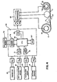
- FIG. 4 there is schematically depicted a motorized film transport mechanism 49 comprising a conventional bi-directional motor 51 and a conventional drive transmission 53.
- the transmission 53 is coupled to the metering sprocket 9 and to respective drive hubs 55 and 57 which engage the take-up spool 1 and a supply spool within the cartridge C.
- the leading end portion L of the filmstrip F is placed over the metering sprocket 9 to position one or more successive perforations P in the leading end portion in engagement with the sprocket.
- the motorized film transport mechanism 49 initially rotates the metering sprocket 9 in order to advance the leading end portion L of the filmstrip F onto the take-up spool 1.
- the take-up spool 1 has respective teeth 59 for engaging the successive perforations P in the leading end portion L of the filmstrip F and is rotated by the motorized transport mechanism 49 at a faster speed than the metering sprocket 9.
- a film tension responsive clutch or other suitable means in the transmission 53 de-couples the metering sprocket 9 from its rotational drive in response to the resulting pull on the filmstrip F caused by engagement of the leading end portion L of the filmstrip to the faster rotating take-up spool 1. Thereafter, the metering sprocket 9 operates in an idling capacity, that is, it is rotated by movement of the filmstrip F from the cartridge C onto the take-up spool 1 and back into the cartridge.
- the four switches SW C , SW B , SW F , and SW M are connected to a conventional digital microcomputer 63 such as used in many cameras.
- the microcomputer 63 includes a central processing unit (CPU) 65, a random access memory (RAM) 67, a read only memory (ROM) 69, a two second timer 71, a three second timer 73, and an up/down counter 75.
- the microcomputer 63 is used to control operation of the motorized film transport mechanism 49 to prewind a substantial length of the filmstrip F onto the take-up spool 1 and to rewind the filmstrip back into the cartridge C.
- the switch SW C is closed by the stop pin 31 on the underside of the counter disk 23 when the disk is initialized to its original "E" setting and is opened by separation of the stop pin from the switch when the disk is first rotated by movement of the metering sprocket 9 to prewind the leading end portion L of the filmstrip F onto the take-up spool 1.
- the switch SW B is closed each time the shutter release button 61 is depressed by the photographer to initiate a film exposure and is opened when the button is released.
- the switch SW F is closed by the sensing finger 41 of the film-on-spool sensor 37 when the sensing finger is moved away from the take-up spool 1 in response to pre-winding of the leading end portion L of the filmstrip F onto the spool and is opened when the sensing finger returns to the spool once the filmstrip is substantially wound off the spool.
- the switch SW M is closed by a cam 77 on the shaft 7, as shown in FIG. 1, each time the metering sprocket 9 is rotated a single revolution. When the metering switch SW M is closed, a metering pulse is generated in the microcomputer 63.
- the metering pulse is counted up in the up/down counter 75 during pre-winding movement of the filmstrip F, to increment the counter by "1", and is counted down during rewinding movement of the filmstrip, to similarly decrement the counter.
- a non-volatile memory 79 or other means, such as a back-up battery, is provided to maintain the pulse count in the up/down counter 75 when the camera is shut down and any filmstrip is present on the take-up spool 1.
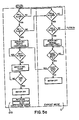
- FIGS. 5a and 5b together form a flow chart which illustrates four routines of the microcomputer 63 which are effected in cooperation with the switches SW C , SW B , SW F , and SW M to control operation of the motorized film transport mechanism 49.
- This mode corresponds to the routine LD of the microcomputer 63. If the switch SW C is closed because the counter disk 23 is in its original "E" setting, the switch SW F is open because no film is present on the take-up spool 1, and the switch SW B is closed because the shutter release button 61 is depressed, the motor 31 is energized to drive the transmission 53 in a pre-wind direction for film movement as depicted by the arrow P in FIG. 4. At this time, the transmission 53 rotates the metering sprocket 9 and the drive hub 55 for rotating the take-up spool 1. The drive hub 57 for rotating the supply spool within the cartridge C is disconnected from the transmission 53, allowing the supply spool to idle.
- the up/down counter 75 begins to count up from “0" by "1", each time a metering pulse is produced in response to closing of the switch SW M when the metering sprocket 9 completes a single revolution. If the switch SW F is closed because the leading end portion L of the filmstrip F has been wound onto the take-up spool 1, the up/down counter 75 re-begins its count up from "0" and the two sec. timer 71 is begun. The substantial length of the filmstrip F, following the leading end portion L, is then pre-wound onto the take-up spool 1. If the up/down counter 75 is incremented by "1" before the two sec. timer 71 times out, the timer is begun again.
- the take-up spool is prevented from withdrawing the remainder of the filmstrip from the cartridge C because a trailing end portion of the filmstrip is attached to the supply spool within the cartridge.
- This end of film condition causes film movement to stall.
- the up/down counter 75 is not incremented by "1" before the two sec. timer 71 times out. This causes the motor 51 first to be de-energized and then to be re-energized in an opposite direction to drive the transmission 53 in a rewind direction for film movement as depicted by the arrow R in FIG. 4.
- the reversed transmission 53 pivots a gear or the like into driving relation with the drive hub 57 for the supply spool within the cartridge C, causing the hub and the spool to be rotated by the transmission.
- the up/down counter 75 begins a countdown of the metering pulses from its total count obtained during pre-winding.
- the up/down counter 75 is decremented by "1"
- the first frame of the filmstrip F will be in the focal plane of the taking lens.
- the motor 51 is de-energized, thereby concluding the load mode LD.
- This mode corresponds to the routine N-L of the microcomputer 63. If, in the load mode LD, the switch SW F is open because the leading end portion L of the filmstrip F is not wound onto the take-up spool 1 after the motor 51 is energized to drive the transmission 53 in the pre-wind direction and if, in the no-load mode N-L, the up/down counter 75 counts up to "3", but the switch SW F has not closed because the take-up spool remains empty, the motor is de-energized and the counter is reset to "0", thereby concluding the no-load mode.
- This mode corresponds to the routine E of the microcomputer 63. If the switch SW C is open because the counter disk 23 is in a numbered setting, rather than in its original "E" setting, the switch SW B is closed because the shutter release button 61 is depressed, and the switch SW F is closed because film is present on the take-up spool 1, the motor 31 is energized to drive the transmission 53 in the rewind direction. As a result, the supply spool within the cartridge C is rotated by the drive hub 57 to rewind an exposed frame into the cartridge, and the take-up spool 1 is rotated by the drive hub 55 to advance a fresh frame off the take-off spool and into the focal plane of the taking lens.
- the motor 51 When the up/down counter 75 is decremented by "1", but the counter has not dropped to "0", the motor 51 will be de-energized, thereby concluding the exposure mode E. Otherwise, if the up/down counter 75 has dropped to "0", then, when the switch SW F is closed because the filmstrip F has been completely wound off the take-up spool, the three sec. timer 73 is begun. When the three sec. timer 73 times out, the leading end portion L of the filmstrip F will have been rewound into the cartridge C. Then, the motor 51 is de-energized and, merely as a precaution, the up/down counter 75 is re-initialized thereby concluding the exposure mode.
- This mode corresponds to the routine O-D of the microcomputer 63. If the switch SW C is closed because the counter disk 23 is in its original "E" setting, but the switch SW F is closed because film is present on the take-up spool 1, such as in the event the rear door 5 is accidentally or inadvertently open before the filmstrip F is completely wound off the take-up spool 1, the motor 51 is energized to drive the transmission 53 in the rewind direction. Then, only when the switch SW F is opened because the remaining film has been wound off the take-up spool 1, the three sec. timer 73 is begun. When the three sec. timer 73 times out, the leading end portion L of the filmstrip F will have been rewound into the cartridge C. Then, the motor 51 is de-energized and, merely as a precaution, the counter 75 is re-initialized, thereby concluding the open door mode.
- the invention has been described with reference to a preferred embodiment. However, it will be appreciated that variations and modifications can be effected within the ordinary skill in the art without departing from the scope of the invention.
- a combination of logic gates or switching circuits which make digital decisions may be used in controlling operation of the motorized film transport mechanism 49.
- a tension sensing member responsive to the sudden increase in film tension arising at the end of pre-winding, when the take-up spool 1 attempts to withdraw the remainder of the filmstrip F from the cartridge C may be used to reverse the motor 51.
- the up/down counter 75 may be connected to a decoder which, in turn, is connected to a liquid crystal display or a light emitting diode array to provide an indication of the frame count.
Landscapes
- Physics & Mathematics (AREA)
- General Physics & Mathematics (AREA)
- Details Of Cameras Including Film Mechanisms (AREA)
- Photographic Developing Apparatuses (AREA)
- Fittings On The Vehicle Exterior For Carrying Loads, And Devices For Holding Or Mounting Articles (AREA)
Abstract
Description
- The invention relates generally to the field of photographic cameras and in particular to those cameras in which a filmstrip is first prewound from a cartridge onto a take-up spool without exposing any of the frames on the filmstrip and then is rewound one frame at a time back into the cartridge after each exposure is completed.
- Typically in a number of
prior art 35 mm cameras, there is included a motorized film transport mechanism. In operation, a leading end portion of the filmstrip extending from a light-tight cartridge loaded in the camera is attached automatically to a take-up spool. The take-up spool is rotated after each exposure is completed to advance successive frames of the filmstrip from the cartridge across the focal plane of a taking lens and onto the take-up spool. Each time the take-up spool is rotated, an unexposed frame on the filmstrip is located in the focal plane of the taking lens and an exposed frame is wound onto the take-up spool. When the fresh film supply has been exhausted, a trailing end portion of the filmstrip remains attached to a supply spool inside the cartridge. This end of film condition is signalled by a sudden increase in the film tension and in the motor current as the take-up spool attempts to withdraw the remainder of the filmstrip from the cartridge. A tension sensing mechanism responds to the increase in film tension, or a detecting circuit responds to the increase in motor current, by reversing the motor drive to rotate the supply spool inside the cartridge. The rotated spool draws the exposed filmstrip off the take-up spool and rewinds it into the cartridge. Then, a rear door of the camera is opened and the cartridge is removed in order to process the filmstrip. - If the rear door of the camera is accidentally or inadvertently opened before the filmstrip is completely wound off the take-up spool and back into the cartridge, the exposed frames on the take-up spool may be ruined by stray light. To prevent this occurance, cameras have been recently provided with a motorized film transport mechanism which prewinds substantially the entire length of the filmstrip onto the take-up spool before any exposures are taken. Then, after each exposure is completed, the filmstrip is rewound one frame at a time back into the cartridge. Thus, the exposed frames will be proteccted within the cartridge from stray light should the rear door be opened prematurely.
- Typically, in a camera which first prewinds the filmstrip onto a take-up spool without exposing any of the frames and then rewinds the filmstrip one frame at a time back into the cartridge after each exposure is completed, selection of either a load (prewind) mode or an expose (rewind) mode of operation of the motorized film transport mechanism may be accomplished manually, as disclosed in U.S. Patent No. 4,251,148, granted February 17, 1981, or automatically, as disclosed in U.S. Patent Nos. 4,460,256, granted July 17, 1984, 4,504,131, granted March 12, 1985, and 4,586,801, granted May 6, 1986. In each patent, the mode determining means suffers the disadvantage that it is mechanically complex and, therefore, is expensive to implement in a camera. Moreover, there is not provided any positive assurance that film is present on the take-up spool when the expose mode is employed. For example, in the '801 patent, a switch for sensing that a cartridge is present in the camera and that a rear door is closed cooperate with a tension sensing mechanism and a mode change-over member to release the member to effect a change-over from the load mode to the expose mode in response to a sudden increase in the film tension produced by the end of prewinding of the filmstrip onto a take-up spool. However, in the '801 patent, it may be possible for the filmstrip to be tensioned because of a snag before the filmstrip is wound onto the take-up spool, in which instance the expose mode would be introduced prematurely.
- The invention provides an improved apparatus for determining the mode of operation of a motorized film transport mechanism in an expose on rewind type camera.
- According to the invention, there is provided a camera having a motorized film transport mechanism which is operable in a load mode after a light-tight cartridge containing an unexposed filmstrip is loaded into the camera and is operable in an expose mode for picture-taking. In the load mode, the transport mechanism first prewinds substantially the entire length of the filmstrip from the cartridge onto a take-up spool without exposing any of the frames on the filmstrip and then rewinds a predetermined length of the filmstrip off the take-up spool to position the first frame for exposure. In the expose mode, the transport mechanism rewinds the filmstrip one frame at a time back into the cartridge after each exposure is completed. When a shutter release member is actuated, a film-on-spool sensing device cooperates with a bi-directional control circuit to operate the transport mechanism in its load mode in response to sensing that the take-up spool is empty and to operate the transport mechanism in its expose mode in response to sensing that film is present on the take-up spool. Thus, the film-on-spool sensing device determines the mode of operation of the transport mechanism by sensing whether or not film is present on the take-up spool as a pre-condition to selecting either the load mode or the expose mode when the shutter release member is actuated. This, in contrast to the prior art described above, is relatively simple and advantageously provides a positive assurance that film is present on the take-up spool when the expose mode is employed.
- A preferred way of carrying out the invention is described below with reference to the drawings, wherein,
- FIG. 1 is a perspective view of an improved apparatus for determining the mode of operation of a motorized film transport mechanism in an expose on rewind type camera, in accordance with a preferred embodiment of the invention;
- FIG. 2 is a top plan view of the improved apparatus depicted in FIG. 1, shown with the rear door opened;
- FIG. 3 is a top plan view of the improved apparatus depicted in FIG. 1, shown with the rear door closed;
- FIG. 4 is a schematic representation of a control circuit included in the improved apparatus; and
- FIGS. 5a and 5b together form a flow chart illustrating operation of the control circuit.
- The invention is disclosed as being embodied preferably in a 35 mm camera. Because the features of this type camera are well known, the description which follows is directed in particular to photographic elements forming part of or cooperating directly with the disclosed embodiment. It is understood, however, that other elements not specifically shown or described may take various forms known to persons of ordinary skill in the art.
- In the type of camera to be described those photographic elements shown in the drawings will be assigned successive reference numbers. Other photographic elements not shown in the drawings are well known or conventional and will not be assigned any reference numbers. Thus, in the description which follows, the absence of a reference number in connection with a mentioned element indicates that such element is not shown in the drawings.
- Referring now to the drawings and in particular to FIG. 1, there is shown certain elements of a 35 mm camera of the type in which substantially the entire length of a filmstrip F is pre-wound from a light-tight film cartridge C onto a take-up spool or
drum 1 before any exposures are taken at anaperture 3. Then, after each exposure at theaperature 3, the filmstrip F is rewound one frame at a time back into the cartridge C. This is done to protect the exposed frames on the filmstrip F in the event arear door 5 of the camera is accidentally or inadvertently opened prematurely, i.e., before the filmstrip is rewound completely into the cartridge. - As shown in FIGS. 1 and 2, a
coaxial shaft 7 connects ametering sprocket 9 and ametering gear 11 to enable the sprocket and the gear to rotate in unison. Themetering sprocket 9 engages successive perforations P in the filmstrip F as the filmstrip is pre-wound onto the take-up spool 1 and is rewound back into the cartridge C. Themetering gear 11 continuously engages acounter gear 13 which is rotatably mounted atop aswing plate 15. Theswing plate 15 is supported on theshaft 7, beneath themetering gear 11, for pivotal movement about the shaft without disengaging thecounter gear 13 from the metering gear. A motion-transmittingstud 17 is coaxially fixed atop thecounter gear 13 and has asingle recess 19 for receiving successiveperipheral teeth 21 of arotatable counter disk 23 to rotate the disk in accordance with rotation of the counter gear. When therear door 5 is closed, as shown in FIG. 3, it abuts against theswing plate 15 to maintain the motion-transmittingstud 17 in a position against at least one of theperipheral teeth 21 of thecounter disk 23. Thecounter disk 23 is located on the outside of the camera and has thirty-six evenly spaced numbered settings represented by the numbers "1, 2, 3, 4, 5,...36" imprinted on the disk. These numbers correspond to successive frames on the filmstrip F. An original empty setting of thecounter disk 23 is represented by the letter "E" imprinted on the disk. This is to indicate that the camera is empty. - When the filmstrip F is pre-wound onto the take-
up spool 1, themetering sprocket 9 is rotated by pre-winding movement of the filmstrip to increment thecounter disk 23 from its original "E" setting to a maximum number setting, such as the "36" setting or a lesser number setting, to indicate the maximum number of unexposed frames on the filmstrip F. Conversely, as the filmstrip F is rewound back into the cartridge C after each exposure is completed, themetering sprocket 9 is rotated by rewinding movement of the filmstrip to decrement thecounter disk 23 one setting at a time from its maximum number setting to indicate the remaining number of unexposed frames on the filmstrip. In operation, the metering sprocket 9, themetering gear 11, thecounter gear 13, and the motion-transmittingstud 17 are each rotated one revolution between successive frames. - When the
rear door 5 is opened, as shown in FIG. 2, a separatingspring 25 urges theswing plate 15 to pivot in a counter-clockwise direction about theshaft 7 into abutment against astop pin 27 on a frame portion of the camera. This will cause the motion-transmittingstud 17 to move out of its position against at least one of theperipheral teeth 21 of thecounter disk 23 to thereby release the disk. Release of thecounter disk 23 allows a relatively light initializingspring 29 to rotate thecounter disk 23 to initialize the disk to its original "E" setting. Astop pin 31 on the underside of thecounter disk 23 contacts afixed pin 33 on a frame portion of the camera to halt thecounter disk 23 at its "E" setting and, simultaneously, to close a normally open switch SWC. - When the
rear door 5 is re-closed, as shown in FIG. 3, it pivots theswing plate 15 in a clockwise direction about theshaft 7 to return the motion-transmittingstud 17 to its position against at least one of theperipheral teeth 21 of thecounter disk 23. A releaseable latch is provided to maintain thedoor 5 closed to hold the motion-transmittingstud 17 in this position. - The take-
up spool 1 includes a relievedannular portion 35 on its periphery having a smaller diameter than the remainder of the take-up spool. A film-on-spool sensor 37 is pivotally mounted on a frame portion of the camera by apivot pin 39 and includes a resilientlyflexible sensing finger 41 for sensing the presence and the absnce of the filmstrip F on the take-up spool 1. Areturn spring 45 urges the film-on-spool sensor 37 to normally position anidler roller 47 on a free end of thesensing member 41 in abutment against the relievedannular portion 35 of the take-up spool 1, as shown in FIG. 2. When a leading end portion L of the filmstrip F is initially wound onto the take-up spool 1, a longitudinal section X of the first convolution of the filmstrip will be spaced opposite the relievedannular portion 35. See FIG. 3. Theidler roller 47 will ride on the longitudinal section X, thereby being separated from the relievedannular portion 35. This causes the film-on-spool sensor 37 to swing in a clockwise direction about thepivot pin 39 to close a normally open switch SWF. - In FIG. 4, there is schematically depicted a motorized
film transport mechanism 49 comprising a conventionalbi-directional motor 51 and aconventional drive transmission 53. As shown, thetransmission 53 is coupled to themetering sprocket 9 and torespective drive hubs spool 1 and a supply spool within the cartridge C. When the cartridge C is loaded in the camera, as shown in FIG. 2, the leading end portion L of the filmstrip F is placed over themetering sprocket 9 to position one or more successive perforations P in the leading end portion in engagement with the sprocket. The motorizedfilm transport mechanism 49 initially rotates themetering sprocket 9 in order to advance the leading end portion L of the filmstrip F onto the take-upspool 1. The take-upspool 1 hasrespective teeth 59 for engaging the successive perforations P in the leading end portion L of the filmstrip F and is rotated by themotorized transport mechanism 49 at a faster speed than themetering sprocket 9. A film tension responsive clutch or other suitable means in thetransmission 53 de-couples themetering sprocket 9 from its rotational drive in response to the resulting pull on the filmstrip F caused by engagement of the leading end portion L of the filmstrip to the faster rotating take-upspool 1. Thereafter, themetering sprocket 9 operates in an idling capacity, that is, it is rotated by movement of the filmstrip F from the cartridge C onto the take-upspool 1 and back into the cartridge. - In addition to the switch SWF associated with the
sensing finger 41 of the film-on-spool sensor 37 and the switch SWC associated with thestop pin 31 on the underside of thecounter disk 23, there are provided respective switches SWB and SWM associated with ashutter release button 61 and themetering sprocket 9. The four switches SWC, SWB, SWF, and SWM are connected to a conventionaldigital microcomputer 63 such as used in many cameras. Themicrocomputer 63 includes a central processing unit (CPU) 65, a random access memory (RAM) 67, a read only memory (ROM) 69, a twosecond timer 71, a threesecond timer 73, and an up/downcounter 75. As is described below, themicrocomputer 63 is used to control operation of the motorizedfilm transport mechanism 49 to prewind a substantial length of the filmstrip F onto the take-upspool 1 and to rewind the filmstrip back into the cartridge C. The switch SWC is closed by thestop pin 31 on the underside of thecounter disk 23 when the disk is initialized to its original "E" setting and is opened by separation of the stop pin from the switch when the disk is first rotated by movement of themetering sprocket 9 to prewind the leading end portion L of the filmstrip F onto the take-upspool 1. The switch SWB is closed each time theshutter release button 61 is depressed by the photographer to initiate a film exposure and is opened when the button is released. The switch SWF is closed by thesensing finger 41 of the film-on-spool sensor 37 when the sensing finger is moved away from the take-upspool 1 in response to pre-winding of the leading end portion L of the filmstrip F onto the spool and is opened when the sensing finger returns to the spool once the filmstrip is substantially wound off the spool. The switch SWM is closed by a cam 77 on theshaft 7, as shown in FIG. 1, each time themetering sprocket 9 is rotated a single revolution. When the metering switch SWM is closed, a metering pulse is generated in themicrocomputer 63. The metering pulse is counted up in the up/down counter 75 during pre-winding movement of the filmstrip F, to increment the counter by "1", and is counted down during rewinding movement of the filmstrip, to similarly decrement the counter. Anon-volatile memory 79 or other means, such as a back-up battery, is provided to maintain the pulse count in the up/down counter 75 when the camera is shut down and any filmstrip is present on the take-upspool 1. - FIGS. 5a and 5b together form a flow chart which illustrates four routines of the
microcomputer 63 which are effected in cooperation with the switches SWC, SWB, SWF, and SWM to control operation of the motorizedfilm transport mechanism 49. - This mode corresponds to the routine LD of the
microcomputer 63. If the switch SWCis closed because thecounter disk 23 is in its original "E" setting, the switch SWF is open because no film is present on the take-upspool 1, and the switch SWB is closed because theshutter release button 61 is depressed, themotor 31 is energized to drive thetransmission 53 in a pre-wind direction for film movement as depicted by the arrow P in FIG. 4. At this time, thetransmission 53 rotates themetering sprocket 9 and thedrive hub 55 for rotating the take-upspool 1. Thedrive hub 57 for rotating the supply spool within the cartridge C is disconnected from thetransmission 53, allowing the supply spool to idle. After themotor 51 is energized, the up/downcounter 75 begins to count up from "0" by "1", each time a metering pulse is produced in response to closing of the switch SWM when themetering sprocket 9 completes a single revolution. If the switch SWF is closed because the leading end portion L of the filmstrip F has been wound onto the take-upspool 1, the up/down counter 75 re-begins its count up from "0" and the two sec.timer 71 is begun. The substantial length of the filmstrip F, following the leading end portion L, is then pre-wound onto the take-upspool 1. If the up/downcounter 75 is incremented by "1" before the two sec.timer 71 times out, the timer is begun again. After the substantial length of the filmstrip F has been pre-wound onto the take-upspool 1, the take-up spool is prevented from withdrawing the remainder of the filmstrip from the cartridge C because a trailing end portion of the filmstrip is attached to the supply spool within the cartridge. This end of film condition causes film movement to stall. As a result, the up/downcounter 75 is not incremented by "1" before the two sec.timer 71 times out. This causes themotor 51 first to be de-energized and then to be re-energized in an opposite direction to drive thetransmission 53 in a rewind direction for film movement as depicted by the arrow R in FIG. 4. The reversedtransmission 53 pivots a gear or the like into driving relation with thedrive hub 57 for the supply spool within the cartridge C, causing the hub and the spool to be rotated by the transmission. Simultaneously, the up/downcounter 75 begins a countdown of the metering pulses from its total count obtained during pre-winding. When the up/downcounter 75 is decremented by "1", the first frame of the filmstrip F will be in the focal plane of the taking lens. Then, themotor 51 is de-energized, thereby concluding the load mode LD. - This mode corresponds to the routine N-L of the
microcomputer 63. If, in the load mode LD, the switch SWF is open because the leading end portion L of the filmstrip F is not wound onto the take-upspool 1 after themotor 51 is energized to drive thetransmission 53 in the pre-wind direction and if, in the no-load mode N-L, the up/down counter 75 counts up to "3", but the switch SWF has not closed because the take-up spool remains empty, the motor is de-energized and the counter is reset to "0", thereby concluding the no-load mode. - This mode corresponds to the routine E of the
microcomputer 63. If the switch SWC is open because thecounter disk 23 is in a numbered setting, rather than in its original "E" setting, the switch SWB is closed because theshutter release button 61 is depressed, and the switch SWF is closed because film is present on the take-upspool 1, themotor 31 is energized to drive thetransmission 53 in the rewind direction. As a result, the supply spool within the cartridge C is rotated by thedrive hub 57 to rewind an exposed frame into the cartridge, and the take-upspool 1 is rotated by thedrive hub 55 to advance a fresh frame off the take-off spool and into the focal plane of the taking lens. When the up/downcounter 75 is decremented by "1", but the counter has not dropped to "0", themotor 51 will be de-energized, thereby concluding the exposure mode E. Otherwise, if the up/downcounter 75 has dropped to "0", then, when the switch SWF is closed because the filmstrip F has been completely wound off the take-up spool, the three sec.timer 73 is begun. When the three sec.timer 73 times out, the leading end portion L of the filmstrip F will have been rewound into the cartridge C. Then, themotor 51 is de-energized and, merely as a precaution, the up/downcounter 75 is re-initialized thereby concluding the exposure mode. - This mode corresponds to the routine O-D of the
microcomputer 63. If the switch SWC is closed because thecounter disk 23 is in its original "E" setting, but the switch SWF is closed because film is present on the take-upspool 1, such as in the event therear door 5 is accidentally or inadvertently open before the filmstrip F is completely wound off the take-upspool 1, themotor 51 is energized to drive thetransmission 53 in the rewind direction. Then, only when the switch SWF is opened because the remaining film has been wound off the take-upspool 1, the three sec.timer 73 is begun. When the three sec.timer 73 times out, the leading end portion L of the filmstrip F will have been rewound into the cartridge C. Then, themotor 51 is de-energized and, merely as a precaution, thecounter 75 is re-initialized, thereby concluding the open door mode. - The invention has been described with reference to a preferred embodiment. However, it will be appreciated that variations and modifications can be effected within the ordinary skill in the art without departing from the scope of the invention. For example, a combination of logic gates or switching circuits which make digital decisions may be used in controlling operation of the motorized
film transport mechanism 49. In another example, a tension sensing member responsive to the sudden increase in film tension arising at the end of pre-winding, when the take-upspool 1 attempts to withdraw the remainder of the filmstrip F from the cartridge C, may be used to reverse themotor 51. In a third example, the up/down counter 75 may be connected to a decoder which, in turn, is connected to a liquid crystal display or a light emitting diode array to provide an indication of the frame count.
Claims (4)
a film-on-spool sensing device (37, SWF) senses the presence of film (F) on the take-up spool (1) and senses that the spool is empty; and
a bi-directional control circuit (63), responsive to actuation of the shutter release member (61) when the film-on-spool sensing device (37, SWF) senses that the take-up spool (1) is empty, operates the motorized film transport mechanism (49, 55, 57) in its load mode, and responsive to actuation of the shutter release member when the film-on-spool sensing device senses that film is present on the take-up spool, operates the motorized film transport mechanism in its picture-taking mode, whereby the film-on-spool sensing device determines the mode of operation of the motorized film transport mechanism.
Applications Claiming Priority (2)
| Application Number | Priority Date | Filing Date | Title |
|---|---|---|---|
| US06/871,040 US4678303A (en) | 1986-06-05 | 1986-06-05 | Film-on-spool sensor for determining mode of operation of film transport mechanism in camera |
| US871040 | 1986-06-05 |
Publications (3)
| Publication Number | Publication Date |
|---|---|
| EP0248331A2 true EP0248331A2 (en) | 1987-12-09 |
| EP0248331A3 EP0248331A3 (en) | 1988-03-16 |
| EP0248331B1 EP0248331B1 (en) | 1992-03-18 |
Family
ID=25356587
Family Applications (1)
| Application Number | Title | Priority Date | Filing Date |
|---|---|---|---|
| EP87107648A Expired EP0248331B1 (en) | 1986-06-05 | 1987-05-26 | Apparatus for determining mode of operation of film transport mechanism in camera |
Country Status (5)
| Country | Link |
|---|---|
| US (1) | US4678303A (en) |
| EP (1) | EP0248331B1 (en) |
| JP (1) | JPS6346432A (en) |
| DE (1) | DE3777451D1 (en) |
| HK (1) | HK78092A (en) |
Cited By (3)
| Publication number | Priority date | Publication date | Assignee | Title |
|---|---|---|---|---|
| EP0277654A3 (en) * | 1987-02-05 | 1989-11-02 | EASTMAN KODAK COMPANY (a New Jersey corporation) | Camera capable of initializing film in non-picture taking condition |
| EP0282968A3 (en) * | 1987-03-16 | 1989-11-08 | Eastman Kodak Company (A New Jersey Corporation) | Camera apparatus for reducing torque load on motorized drive during film initialization |
| GB2287545A (en) * | 1994-03-15 | 1995-09-20 | Concord Camera Corp | Prewind camera with film interlock |
Families Citing this family (4)
| Publication number | Priority date | Publication date | Assignee | Title |
|---|---|---|---|---|
| JPS62201861U (en) * | 1986-06-13 | 1987-12-23 | ||
| JPH0460530A (en) * | 1990-06-28 | 1992-02-26 | Nikon Corp | Camera film feed control device |
| US5510865A (en) * | 1994-09-15 | 1996-04-23 | Eastman Kodak Company | Camera with mid-roll rewind mode |
| US5467159A (en) * | 1995-01-03 | 1995-11-14 | Eastman Kodak Company | Film transport mechanism for camera |
Family Cites Families (7)
| Publication number | Priority date | Publication date | Assignee | Title |
|---|---|---|---|---|
| DE2855312A1 (en) * | 1978-12-21 | 1980-07-03 | Agfa Gevaert Ag | PHOTOGRAPHIC CAMERA |
| US4460256A (en) * | 1980-11-26 | 1984-07-17 | Ricoh Company, Ltd. | Film feeding system of a camera |
| DE3202398A1 (en) * | 1981-01-27 | 1982-11-25 | Canon K.K., Tokyo | "MOTORIZED CAMERA" |
| US4504131A (en) * | 1981-02-13 | 1985-03-12 | Canon Kabushiki Kaisha | Camera |
| US4419001A (en) * | 1981-05-29 | 1983-12-06 | Minolta Camera Kabushiki Kaisha | Motor driven film wind-up and rewind device for cameras |
| US4494842A (en) * | 1981-11-13 | 1985-01-22 | Canon Kabushiki Kaisha | Automatic rewinding device for film in camera |
| US4586801A (en) * | 1983-10-12 | 1986-05-06 | Fuji Photo Film Co., Ltd. | Mode changing mechanism for pre-winding type photographic camera |
-
1986
- 1986-06-05 US US06/871,040 patent/US4678303A/en not_active Expired - Fee Related
-
1987
- 1987-05-26 EP EP87107648A patent/EP0248331B1/en not_active Expired
- 1987-05-26 DE DE8787107648T patent/DE3777451D1/en not_active Expired - Fee Related
- 1987-05-29 JP JP62134742A patent/JPS6346432A/en active Pending
-
1992
- 1992-10-15 HK HK780/92A patent/HK78092A/en not_active IP Right Cessation
Cited By (4)
| Publication number | Priority date | Publication date | Assignee | Title |
|---|---|---|---|---|
| EP0277654A3 (en) * | 1987-02-05 | 1989-11-02 | EASTMAN KODAK COMPANY (a New Jersey corporation) | Camera capable of initializing film in non-picture taking condition |
| EP0282968A3 (en) * | 1987-03-16 | 1989-11-08 | Eastman Kodak Company (A New Jersey Corporation) | Camera apparatus for reducing torque load on motorized drive during film initialization |
| GB2287545A (en) * | 1994-03-15 | 1995-09-20 | Concord Camera Corp | Prewind camera with film interlock |
| GB2287545B (en) * | 1994-03-15 | 1996-08-28 | Concord Camera Corp | Prewind camera with film interlock |
Also Published As
| Publication number | Publication date |
|---|---|
| DE3777451D1 (en) | 1992-04-23 |
| HK78092A (en) | 1992-10-23 |
| US4678303A (en) | 1987-07-07 |
| EP0248331A3 (en) | 1988-03-16 |
| EP0248331B1 (en) | 1992-03-18 |
| JPS6346432A (en) | 1988-02-27 |
Similar Documents
| Publication | Publication Date | Title |
|---|---|---|
| CA1219487A (en) | Automatic film rewinding camera | |
| US4687311A (en) | Film-on-spool sensor for controlling frame counter | |
| USRE33436E (en) | Film feeding system of a camera | |
| KR0142227B1 (en) | Camera for use with film cassette having film-exposure status indicator | |
| US4676621A (en) | Frame counter initialization sensor for triggering film rewind when camera door opened prematurely | |
| US4671636A (en) | Film-on-spool sensor for triggering film rewind when camera door opened prematurely | |
| US4494842A (en) | Automatic rewinding device for film in camera | |
| US4324469A (en) | Camera adapted to faciliate removal and reuse of partially exposed film cassettes | |
| EP0248331B1 (en) | Apparatus for determining mode of operation of film transport mechanism in camera | |
| US4653886A (en) | Film-on-spool sensor for preventing initialization of frame counter | |
| US4351595A (en) | Motor drive camera | |
| US4752795A (en) | Camera capable of initializing film in non-picture taking mode | |
| US4896180A (en) | Film initialization reassuring mechanism | |
| US5166715A (en) | Camera with film take-up confirming mechanism | |
| US3854142A (en) | Data recording camera | |
| EP0282968B1 (en) | Camera apparatus for reducing torque load on motorized drive during film initialization | |
| JP2810555B2 (en) | Camera and film feeder | |
| JPS6242490B2 (en) | ||
| US6435739B1 (en) | Camera having a spring loaded mechanism for driving a light-shielding door member | |
| JPH0719023B2 (en) | Spare roll camera | |
| US6628896B2 (en) | Motorized single use camera | |
| JP2961700B2 (en) | Camera and camera cartridge index reader | |
| JP2763382B2 (en) | Camera and film feeder | |
| JP3216429B2 (en) | Film exposure / non-exposure discrimination system | |
| JPS63257737A (en) | Film feeding device for camera |
Legal Events
| Date | Code | Title | Description |
|---|---|---|---|
| PUAI | Public reference made under article 153(3) epc to a published international application that has entered the european phase |
Free format text: ORIGINAL CODE: 0009012 |
|
| AK | Designated contracting states |
Kind code of ref document: A2 Designated state(s): DE FR GB |
|
| PUAL | Search report despatched |
Free format text: ORIGINAL CODE: 0009013 |
|
| AK | Designated contracting states |
Kind code of ref document: A3 Designated state(s): DE FR GB |
|
| 17P | Request for examination filed |
Effective date: 19880819 |
|
| 17Q | First examination report despatched |
Effective date: 19910228 |
|
| GRAA | (expected) grant |
Free format text: ORIGINAL CODE: 0009210 |
|
| AK | Designated contracting states |
Kind code of ref document: B1 Designated state(s): DE FR GB |
|
| REF | Corresponds to: |
Ref document number: 3777451 Country of ref document: DE Date of ref document: 19920423 |
|
| ET | Fr: translation filed | ||
| PLBE | No opposition filed within time limit |
Free format text: ORIGINAL CODE: 0009261 |
|
| STAA | Information on the status of an ep patent application or granted ep patent |
Free format text: STATUS: NO OPPOSITION FILED WITHIN TIME LIMIT |
|
| 26N | No opposition filed | ||
| PGFP | Annual fee paid to national office [announced via postgrant information from national office to epo] |
Ref country code: FR Payment date: 19950509 Year of fee payment: 9 |
|
| PGFP | Annual fee paid to national office [announced via postgrant information from national office to epo] |
Ref country code: DE Payment date: 19950529 Year of fee payment: 9 |
|
| PG25 | Lapsed in a contracting state [announced via postgrant information from national office to epo] |
Ref country code: FR Effective date: 19970131 |
|
| PG25 | Lapsed in a contracting state [announced via postgrant information from national office to epo] |
Ref country code: DE Effective date: 19970201 |
|
| REG | Reference to a national code |
Ref country code: FR Ref legal event code: ST |
|
| PGFP | Annual fee paid to national office [announced via postgrant information from national office to epo] |
Ref country code: GB Payment date: 19970408 Year of fee payment: 11 |
|
| PG25 | Lapsed in a contracting state [announced via postgrant information from national office to epo] |
Ref country code: GB Free format text: LAPSE BECAUSE OF NON-PAYMENT OF DUE FEES Effective date: 19980526 |
|
| GBPC | Gb: european patent ceased through non-payment of renewal fee |
Effective date: 19980526 |