EP0248328A2 - Alignment and focusing apparatus - Google Patents
Alignment and focusing apparatus Download PDFInfo
- Publication number
- EP0248328A2 EP0248328A2 EP87107636A EP87107636A EP0248328A2 EP 0248328 A2 EP0248328 A2 EP 0248328A2 EP 87107636 A EP87107636 A EP 87107636A EP 87107636 A EP87107636 A EP 87107636A EP 0248328 A2 EP0248328 A2 EP 0248328A2
- Authority
- EP
- European Patent Office
- Prior art keywords
- radiation
- source
- array
- image
- ized
- Prior art date
- Legal status (The legal status is an assumption and is not a legal conclusion. Google has not performed a legal analysis and makes no representation as to the accuracy of the status listed.)
- Withdrawn
Links
Images
Classifications
-
- G—PHYSICS
- G01—MEASURING; TESTING
- G01B—MEASURING LENGTH, THICKNESS OR SIMILAR LINEAR DIMENSIONS; MEASURING ANGLES; MEASURING AREAS; MEASURING IRREGULARITIES OF SURFACES OR CONTOURS
- G01B11/00—Measuring arrangements characterised by the use of optical techniques
-
- G—PHYSICS
- G01—MEASURING; TESTING
- G01B—MEASURING LENGTH, THICKNESS OR SIMILAR LINEAR DIMENSIONS; MEASURING ANGLES; MEASURING AREAS; MEASURING IRREGULARITIES OF SURFACES OR CONTOURS
- G01B11/00—Measuring arrangements characterised by the use of optical techniques
- G01B11/02—Measuring arrangements characterised by the use of optical techniques for measuring length, width or thickness
- G01B11/026—Measuring arrangements characterised by the use of optical techniques for measuring length, width or thickness by measuring distance between sensor and object
-
- G—PHYSICS
- G02—OPTICS
- G02B—OPTICAL ELEMENTS, SYSTEMS OR APPARATUS
- G02B7/00—Mountings, adjusting means, or light-tight connections, for optical elements
- G02B7/28—Systems for automatic generation of focusing signals
Definitions
- the present invention relates to an apparatus according to the preamble of claim 1.
- the object image would fall on the linear array and the number of detector elements covered by the image would then be a measure of the width. Unless the optical system is aimed quite accurately, the image of the object might extend beyond one end of the array and the system would fail. A second problem is also encountered whtn the system is not in accurate focus because the image on the detectors is fuzzy and the ends of the image are difficult to accurately locate. Of course, increasing the number of detector elements in the array could minimize the problem of the image extending beyond the ends of the array, but the cost of detector elements is high and this solution would still not solve the problem of focus error.
- the optical system used to transmit the image of the remote object onto the detector array is used in reverse to project a line of radiation onto the remote object from a position that is optically at the same distance and orientation with respect to the object as the detector array.
- the optical system is adjusted until the projected line of radiation is in focus thus assuring that the image of the object on the detector array will be in focus.
- the system is also moved until the projected radiation is at the desired location on the object thus assuring that the desired location of the object will fall on the detector array.
- a detector array 10 is shown positioned to receive radiation from a remote object 12, which may be one of a plurality of items moving along a conveyor belt, for example.
- the array 10 is comprised of a plurality of photo sensitive detector elements 13 such as CCD's in a line extending along an axis 14 perpendicular to the plane of the Figure 1.
- the detector elements 13 of array 10 will view or "see" a line of predetermined length on the object 12 extending along an axis parallel to axis 14.
- a lens 15, which may be a series of interconnected lenses, is shown movable along an axis 16 between array 10 and object 12 in the directions shown by arrow 17.
- lens 15 When properly positioned, lens 15 will focus radiation from object 12 along lines such as shown by reference numerals 20 and 21 in Figure 1 on the detector array 10.
- the area viewed by array 10 on object 12 was not visible or otherwise early detectable and in aligning and focusing the system, many readings from the detector array needed to be taken or other complex alignment system had to be used in order to know what area of the object was being "seen”.
- the present invention employs a partly silvered mirror 30 mounted in the path of radiation from object 12 and arranged at an angle to axis 16.
- An elongated source of radiation 34 which may be a linear filament lamp and which extends along an axis 35 parallel to axis 14 is mounted above mirror 30 at a distance which is optically equivalent to the distance from mirror 30 to array 10.
- Source 34 is shown connected by conductors 36 and 38 to a series connected energy source 40 and closable switch 42. When switch 42 is closed, energy source 40, which may be a battery, will energize radiation source 34 causing it to emit radiation such as visible light along its axis 35.
- This radiation is reflected by mirror 30 along axis 16 so as to be focussed by lens 15 as a line of radiation shown by dotted line 43 on object 12.
- This line may be viewed by an operator or otherwise detected so that by moving lens 15 along axis 16 the image is caused to be in good focus.
- the image 43 of source 34 may be located in a desirable area of object 12. Since the source 34 and array 10 are optically at the same position in the optical system, when the image 43 of source 34 is in focus on object 12, object 12 will be in focus on detector array 10. Also since elongated source 34 is of optically equivalent length to the detectors 13 of array 10, image 43 on object 12 will correspond with the area of object 12 being "seen" by array 10. After the system is thus adjusted, switch 42 may be opened to extinguish lamp 34 and the system will thereafter operate in normal fashion.
- light source 34 may be an infrared source and may be energized by a modulated alternating energy source 40.
- the source could be further away from the object if it were enough larger that the image projected onto the object were still the same size as the area being viewed by the sensor.
- the source could also be replaced by two essentially point or spot sources corresponding to the end points of the line or by a bracket which defined or was descriptive of the area being viewed by the detectors.
- the linear array 10 could be arranged in the form of a square, or cross or other shape so long as the light source 34 was optically equivalent.
Landscapes
- Physics & Mathematics (AREA)
- General Physics & Mathematics (AREA)
- Optics & Photonics (AREA)
- Transforming Light Signals Into Electric Signals (AREA)
- Studio Devices (AREA)
- Automatic Focus Adjustment (AREA)
- Apparatus For Radiation Diagnosis (AREA)
- Length Measuring Devices By Optical Means (AREA)
Abstract
Description
- The present invention relates to an apparatus according to the preamble of claim 1.
- In the use of radiation detector arrays, particularly those referred to as "linear arrays" consisting of a plurality of radiation detectors such as CCD's or CID's arranged in a line, it is often difficult to determine the part of a remote object from which the detector array receives radiation. In photography, the problem is not severe since the human operator has a viewfinder which shows, at least generally, where the detector array is looking. But in many cases, such as assembly line monitoring, the system does not employ a viewfinder or a human operator is not always available to aim through a viewfinder. this problem is quite serious when the equipment must be accurately aimed at a predetermined area on the object. For example, a system might be set up to measure the width of object passing by on a conveyor belt. The object image would fall on the linear array and the number of detector elements covered by the image would then be a measure of the width. Unless the optical system is aimed quite accurately, the image of the object might extend beyond one end of the array and the system would fail. A second problem is also encountered whtn the system is not in accurate focus because the image on the detectors is fuzzy and the ends of the image are difficult to accurately locate. Of course, increasing the number of detector elements in the array could minimize the problem of the image extending beyond the ends of the array, but the cost of detector elements is high and this solution would still not solve the problem of focus error.
- Therefore, it is the object of the present invention to devise a simple apparatus as an alignment and focusing aid for a detecting device. This object is achieved according to the characterizing features of claim 1. Further advantageous embodiments of the inventive apparatus may be taken from the subclaims.
- The present invention overcomes both of the problems of the prior art in a simple and economical manner. In the present invention, the optical system used to transmit the image of the remote object onto the detector array, is used in reverse to project a line of radiation onto the remote object from a position that is optically at the same distance and orientation with respect to the object as the detector array. The optical system is adjusted until the projected line of radiation is in focus thus assuring that the image of the object on the detector array will be in focus. The system is also moved until the projected radiation is at the desired location on the object thus assuring that the desired location of the object will fall on the detector array.
- With respect to the figures of the attached drawings the invention shall be further explained, where
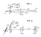
- Figure 1 shows a schematic side view of the optical system of the invention; and
- Figure 2 shows a perspective view of the invention
- In Figure 1 and 2, a
detector array 10 is shown positioned to receive radiation from aremote object 12, which may be one of a plurality of items moving along a conveyor belt, for example. Thearray 10 is comprised of a plurality of photosensitive detector elements 13 such as CCD's in a line extending along anaxis 14 perpendicular to the plane of the Figure 1. As such thedetector elements 13 ofarray 10 will view or "see" a line of predetermined length on theobject 12 extending along an axis parallel toaxis 14. Alens 15, which may be a series of interconnected lenses, is shown movable along anaxis 16 betweenarray 10 andobject 12 in the directions shown byarrow 17. When properly positioned,lens 15 will focus radiation fromobject 12 along lines such as shown byreference numerals detector array 10. In the prior art, the area viewed byarray 10 onobject 12 was not visible or otherwise early detectable and in aligning and focusing the system, many readings from the detector array needed to be taken or other complex alignment system had to be used in order to know what area of the object was being "seen". - To overcome this problem, the present invention employs a partly
silvered mirror 30 mounted in the path of radiation fromobject 12 and arranged at an angle toaxis 16. An elongated source ofradiation 34 which may be a linear filament lamp and which extends along anaxis 35 parallel toaxis 14 is mounted abovemirror 30 at a distance which is optically equivalent to the distance frommirror 30 toarray 10.Source 34 is shown connected byconductors energy source 40 andclosable switch 42. Whenswitch 42 is closed,energy source 40, which may be a battery, will energizeradiation source 34 causing it to emit radiation such as visible light along itsaxis 35. This radiation is reflected bymirror 30 alongaxis 16 so as to be focussed bylens 15 as a line of radiation shown by dotted line 43 onobject 12. This line may be viewed by an operator or otherwise detected so that by movinglens 15 alongaxis 16 the image is caused to be in good focus. By moving thehousing containing lens 15,mirror 30,radiation source 34 anddetector array 10, the image 43 ofsource 34 may be located in a desirable area ofobject 12. Since thesource 34 andarray 10 are optically at the same position in the optical system, when the image 43 ofsource 34 is in focus onobject 12,object 12 will be in focus ondetector array 10. Also sinceelongated source 34 is of optically equivalent length to thedetectors 13 ofarray 10, image 43 onobject 12 will correspond with the area ofobject 12 being "seen" byarray 10. After the system is thus adjusted,switch 42 may be opened to extinguishlamp 34 and the system will thereafter operate in normal fashion. - Thus it is seen that by unique yet and inexpensive means I have overcome the problems encountered in the prior art, and have provided a system which assures that the area being viewed by a linear array is in proper focus and is correctly positioned. Many changes to the preferred embodiment will occur to those skilled in the art. For example,
light source 34 may be an infrared source and may be energized by a modulatedalternating energy source 40. The source could be further away from the object if it were enough larger that the image projected onto the object were still the same size as the area being viewed by the sensor. The source could also be replaced by two essentially point or spot sources corresponding to the end points of the line or by a bracket which defined or was descriptive of the area being viewed by the detectors. Also, thelinear array 10 could be arranged in the form of a square, or cross or other shape so long as thelight source 34 was optically equivalent.
Claims (7)
a source of radiation (34); and radiation transmitting means (15, 30) positioned between the detectors (13) and the remote object (12) at a position such that the source is in an optical position discriminative of the position of the array (10) so that radiation from the source is reflected to form an image (43) on the remote object descriptive of the area.
Applications Claiming Priority (2)
| Application Number | Priority Date | Filing Date | Title |
|---|---|---|---|
| US06/870,065 US4742217A (en) | 1986-06-02 | 1986-06-02 | Projection alignment and focusing aid |
| US870065 | 1986-06-02 |
Publications (2)
| Publication Number | Publication Date |
|---|---|
| EP0248328A2 true EP0248328A2 (en) | 1987-12-09 |
| EP0248328A3 EP0248328A3 (en) | 1989-07-05 |
Family
ID=25354729
Family Applications (1)
| Application Number | Title | Priority Date | Filing Date |
|---|---|---|---|
| EP87107636A Withdrawn EP0248328A3 (en) | 1986-06-02 | 1987-05-26 | Alignment and focusing apparatus |
Country Status (3)
| Country | Link |
|---|---|
| US (1) | US4742217A (en) |
| EP (1) | EP0248328A3 (en) |
| JP (1) | JPS633204A (en) |
Cited By (1)
| Publication number | Priority date | Publication date | Assignee | Title |
|---|---|---|---|---|
| FR2675599A1 (en) * | 1991-04-22 | 1992-10-23 | Digital Stream Corp | Wireless input system for computer |
Families Citing this family (4)
| Publication number | Priority date | Publication date | Assignee | Title |
|---|---|---|---|---|
| US5142135A (en) * | 1990-10-19 | 1992-08-25 | Allen-Bradley Company, Inc. | Optical sensor projecting an image of the sensor for alignment purposes |
| US5648719A (en) * | 1992-06-19 | 1997-07-15 | Honeywell Inc. | Magnetic sensor with characteristics that are changeable by an external magnetic device |
| DE10131217A1 (en) * | 2001-06-28 | 2003-01-09 | Solvay Pharm Gmbh | 3-phenyl-3,7-diazabicyclo 3,3,1 nonane compounds and processes for their preparation and medicaments containing these compounds |
| US6923558B1 (en) | 2002-05-28 | 2005-08-02 | Nextengine, Inc. | Filament alignment mechanism for high accuracy lamps |
Family Cites Families (4)
| Publication number | Priority date | Publication date | Assignee | Title |
|---|---|---|---|---|
| US3360635A (en) * | 1967-02-23 | 1967-12-26 | Digitronics Corp | Head for reading a perforated record medium |
| US3634696A (en) * | 1970-03-09 | 1972-01-11 | Ernest Wildhaber | Radiation-sensitive optical scanning apparatus |
| US3809894A (en) * | 1970-09-18 | 1974-05-07 | Creative Logic Corp | Optical scanner |
| FR2512949A1 (en) * | 1981-09-16 | 1983-03-18 | Merck Georges | OPTICAL MEASURING DEVICE BY COAXIAL LIGHTING |
-
1986
- 1986-06-02 US US06/870,065 patent/US4742217A/en not_active Expired - Fee Related
-
1987
- 1987-05-26 EP EP87107636A patent/EP0248328A3/en not_active Withdrawn
- 1987-06-02 JP JP62138847A patent/JPS633204A/en active Pending
Cited By (1)
| Publication number | Priority date | Publication date | Assignee | Title |
|---|---|---|---|---|
| FR2675599A1 (en) * | 1991-04-22 | 1992-10-23 | Digital Stream Corp | Wireless input system for computer |
Also Published As
| Publication number | Publication date |
|---|---|
| JPS633204A (en) | 1988-01-08 |
| EP0248328A3 (en) | 1989-07-05 |
| US4742217A (en) | 1988-05-03 |
Similar Documents
| Publication | Publication Date | Title |
|---|---|---|
| US4936676A (en) | Surface position sensor | |
| US4752799A (en) | Optical proximity sensing optics | |
| US6002124A (en) | Portable image scanner with optical position sensors | |
| EP0113984B1 (en) | Portable video camera with automatic focusing device | |
| SE9804009D0 (en) | Angle detection method for bending machines, angle detection apparatus and angle sensors for this | |
| CA2132111C (en) | Inspection of translucent containers | |
| US4534645A (en) | Automatic lens meter | |
| US3658426A (en) | Alignment telescope | |
| US5637864A (en) | Optical inspection of translucent containers for vertical checks and split seams in the container sidewalls | |
| US4833497A (en) | Apparatus for adjusting focus in the macro-photographing mode of an automatic focus camera | |
| US4801212A (en) | Optical system for radiation thermometer | |
| US4469939A (en) | Distance measuring apparatus | |
| EP0248328A2 (en) | Alignment and focusing apparatus | |
| GB2079561A (en) | Secondary alignment target for an electro-optical alignment measuring system | |
| US3901607A (en) | High aperture reflection photodetector apparatus | |
| EP0110937A1 (en) | Apparatus for measuring the dimensions of cylindrical objects by means of a scanning laser beam. | |
| US4851913A (en) | Picture recording apparatus | |
| US5159378A (en) | Light projector for range finding device | |
| US4123765A (en) | Automatic focus adjusting device | |
| US4611115A (en) | Laser etch monitoring system | |
| US3002419A (en) | Alignment theodolite | |
| US5142135A (en) | Optical sensor projecting an image of the sensor for alignment purposes | |
| US4154532A (en) | High precision optical alignment system | |
| KR890001454B1 (en) | Focusing device | |
| US4707614A (en) | Self-contained portable photoelectric gas measuring and warning apparatus |
Legal Events
| Date | Code | Title | Description |
|---|---|---|---|
| PUAI | Public reference made under article 153(3) epc to a published international application that has entered the european phase |
Free format text: ORIGINAL CODE: 0009012 |
|
| AK | Designated contracting states |
Kind code of ref document: A2 Designated state(s): DE FR GB IT |
|
| PUAL | Search report despatched |
Free format text: ORIGINAL CODE: 0009013 |
|
| AK | Designated contracting states |
Kind code of ref document: A3 Designated state(s): DE FR GB IT |
|
| RTI1 | Title (correction) | ||
| 17P | Request for examination filed |
Effective date: 19891227 |
|
| 17Q | First examination report despatched |
Effective date: 19901206 |
|
| STAA | Information on the status of an ep patent application or granted ep patent |
Free format text: STATUS: THE APPLICATION HAS BEEN WITHDRAWN |
|
| 18W | Application withdrawn |
Withdrawal date: 19910923 |
|
| R18W | Application withdrawn (corrected) |
Effective date: 19910923 |
|
| RIN1 | Information on inventor provided before grant (corrected) |
Inventor name: WILWERDING, DENNIS J. |