EP0248317B1 - Reticular spatial structure - Google Patents
Reticular spatial structure Download PDFInfo
- Publication number
- EP0248317B1 EP0248317B1 EP87107596A EP87107596A EP0248317B1 EP 0248317 B1 EP0248317 B1 EP 0248317B1 EP 87107596 A EP87107596 A EP 87107596A EP 87107596 A EP87107596 A EP 87107596A EP 0248317 B1 EP0248317 B1 EP 0248317B1
- Authority
- EP
- European Patent Office
- Prior art keywords
- rod
- elements
- length
- reticular
- spatial structure
- Prior art date
- Legal status (The legal status is an assumption and is not a legal conclusion. Google has not performed a legal analysis and makes no representation as to the accuracy of the status listed.)
- Expired - Lifetime
Links
Images

Classifications
-
- E—FIXED CONSTRUCTIONS
- E04—BUILDING
- E04B—GENERAL BUILDING CONSTRUCTIONS; WALLS, e.g. PARTITIONS; ROOFS; FLOORS; CEILINGS; INSULATION OR OTHER PROTECTION OF BUILDINGS
- E04B1/00—Constructions in general; Structures which are not restricted either to walls, e.g. partitions, or floors or ceilings or roofs
- E04B1/18—Structures comprising elongated load-supporting parts, e.g. columns, girders, skeletons
- E04B1/19—Three-dimensional [3D] framework structures
- E04B1/1903—Connecting nodes specially adapted therefor
- E04B1/1906—Connecting nodes specially adapted therefor with central spherical, semispherical or polyhedral connecting element
-
- E—FIXED CONSTRUCTIONS
- E04—BUILDING
- E04B—GENERAL BUILDING CONSTRUCTIONS; WALLS, e.g. PARTITIONS; ROOFS; FLOORS; CEILINGS; INSULATION OR OTHER PROTECTION OF BUILDINGS
- E04B1/00—Constructions in general; Structures which are not restricted either to walls, e.g. partitions, or floors or ceilings or roofs
- E04B1/32—Arched structures; Vaulted structures; Folded structures
- E04B1/3211—Structures with a vertical rotation axis or the like, e.g. semi-spherical structures
-
- E—FIXED CONSTRUCTIONS
- E04—BUILDING
- E04B—GENERAL BUILDING CONSTRUCTIONS; WALLS, e.g. PARTITIONS; ROOFS; FLOORS; CEILINGS; INSULATION OR OTHER PROTECTION OF BUILDINGS
- E04B7/00—Roofs; Roof construction with regard to insulation
- E04B7/08—Vaulted roofs
- E04B7/10—Shell structures, e.g. of hyperbolic-parabolic shape; Grid-like formations acting as shell structures; Folded structures
- E04B7/105—Grid-like structures
-
- E—FIXED CONSTRUCTIONS
- E04—BUILDING
- E04B—GENERAL BUILDING CONSTRUCTIONS; WALLS, e.g. PARTITIONS; ROOFS; FLOORS; CEILINGS; INSULATION OR OTHER PROTECTION OF BUILDINGS
- E04B1/00—Constructions in general; Structures which are not restricted either to walls, e.g. partitions, or floors or ceilings or roofs
- E04B1/18—Structures comprising elongated load-supporting parts, e.g. columns, girders, skeletons
- E04B1/19—Three-dimensional [3D] framework structures
- E04B1/1903—Connecting nodes specially adapted therefor
- E04B1/1909—Connecting nodes specially adapted therefor with central cylindrical connecting element
-
- E—FIXED CONSTRUCTIONS
- E04—BUILDING
- E04B—GENERAL BUILDING CONSTRUCTIONS; WALLS, e.g. PARTITIONS; ROOFS; FLOORS; CEILINGS; INSULATION OR OTHER PROTECTION OF BUILDINGS
- E04B1/00—Constructions in general; Structures which are not restricted either to walls, e.g. partitions, or floors or ceilings or roofs
- E04B1/18—Structures comprising elongated load-supporting parts, e.g. columns, girders, skeletons
- E04B1/19—Three-dimensional [3D] framework structures
- E04B2001/1924—Struts specially adapted therefor
- E04B2001/1927—Struts specially adapted therefor of essentially circular cross section
-
- E—FIXED CONSTRUCTIONS
- E04—BUILDING
- E04B—GENERAL BUILDING CONSTRUCTIONS; WALLS, e.g. PARTITIONS; ROOFS; FLOORS; CEILINGS; INSULATION OR OTHER PROTECTION OF BUILDINGS
- E04B1/00—Constructions in general; Structures which are not restricted either to walls, e.g. partitions, or floors or ceilings or roofs
- E04B1/18—Structures comprising elongated load-supporting parts, e.g. columns, girders, skeletons
- E04B1/19—Three-dimensional [3D] framework structures
- E04B2001/1924—Struts specially adapted therefor
- E04B2001/1942—Struts adjustable in length
-
- E—FIXED CONSTRUCTIONS
- E04—BUILDING
- E04B—GENERAL BUILDING CONSTRUCTIONS; WALLS, e.g. PARTITIONS; ROOFS; FLOORS; CEILINGS; INSULATION OR OTHER PROTECTION OF BUILDINGS
- E04B1/00—Constructions in general; Structures which are not restricted either to walls, e.g. partitions, or floors or ceilings or roofs
- E04B1/18—Structures comprising elongated load-supporting parts, e.g. columns, girders, skeletons
- E04B1/19—Three-dimensional [3D] framework structures
- E04B2001/1957—Details of connections between nodes and struts
- E04B2001/196—Screw connections with axis parallel to the main axis of the strut
-
- E—FIXED CONSTRUCTIONS
- E04—BUILDING
- E04B—GENERAL BUILDING CONSTRUCTIONS; WALLS, e.g. PARTITIONS; ROOFS; FLOORS; CEILINGS; INSULATION OR OTHER PROTECTION OF BUILDINGS
- E04B1/00—Constructions in general; Structures which are not restricted either to walls, e.g. partitions, or floors or ceilings or roofs
- E04B1/18—Structures comprising elongated load-supporting parts, e.g. columns, girders, skeletons
- E04B1/19—Three-dimensional [3D] framework structures
- E04B2001/1957—Details of connections between nodes and struts
- E04B2001/1963—Screw connections with axis at an angle, e.g. perpendicular, to the main axis of the strut
-
- E—FIXED CONSTRUCTIONS
- E04—BUILDING
- E04B—GENERAL BUILDING CONSTRUCTIONS; WALLS, e.g. PARTITIONS; ROOFS; FLOORS; CEILINGS; INSULATION OR OTHER PROTECTION OF BUILDINGS
- E04B1/00—Constructions in general; Structures which are not restricted either to walls, e.g. partitions, or floors or ceilings or roofs
- E04B1/18—Structures comprising elongated load-supporting parts, e.g. columns, girders, skeletons
- E04B1/19—Three-dimensional [3D] framework structures
- E04B2001/1981—Three-dimensional [3D] framework structures characterised by the grid type of the outer planes of the framework
- E04B2001/1987—Three-dimensional [3D] framework structures characterised by the grid type of the outer planes of the framework triangular grid
-
- E—FIXED CONSTRUCTIONS
- E04—BUILDING
- E04B—GENERAL BUILDING CONSTRUCTIONS; WALLS, e.g. PARTITIONS; ROOFS; FLOORS; CEILINGS; INSULATION OR OTHER PROTECTION OF BUILDINGS
- E04B1/00—Constructions in general; Structures which are not restricted either to walls, e.g. partitions, or floors or ceilings or roofs
- E04B1/32—Arched structures; Vaulted structures; Folded structures
- E04B2001/3217—Auxiliary supporting devices used during erection of the arched structures
-
- E—FIXED CONSTRUCTIONS
- E04—BUILDING
- E04B—GENERAL BUILDING CONSTRUCTIONS; WALLS, e.g. PARTITIONS; ROOFS; FLOORS; CEILINGS; INSULATION OR OTHER PROTECTION OF BUILDINGS
- E04B1/00—Constructions in general; Structures which are not restricted either to walls, e.g. partitions, or floors or ceilings or roofs
- E04B1/32—Arched structures; Vaulted structures; Folded structures
- E04B2001/3235—Arched structures; Vaulted structures; Folded structures having a grid frame
- E04B2001/3241—Frame connection details
- E04B2001/3247—Nodes
-
- E—FIXED CONSTRUCTIONS
- E04—BUILDING
- E04B—GENERAL BUILDING CONSTRUCTIONS; WALLS, e.g. PARTITIONS; ROOFS; FLOORS; CEILINGS; INSULATION OR OTHER PROTECTION OF BUILDINGS
- E04B1/00—Constructions in general; Structures which are not restricted either to walls, e.g. partitions, or floors or ceilings or roofs
- E04B1/32—Arched structures; Vaulted structures; Folded structures
- E04B2001/3235—Arched structures; Vaulted structures; Folded structures having a grid frame
- E04B2001/3252—Covering details
-
- E—FIXED CONSTRUCTIONS
- E04—BUILDING
- E04B—GENERAL BUILDING CONSTRUCTIONS; WALLS, e.g. PARTITIONS; ROOFS; FLOORS; CEILINGS; INSULATION OR OTHER PROTECTION OF BUILDINGS
- E04B1/00—Constructions in general; Structures which are not restricted either to walls, e.g. partitions, or floors or ceilings or roofs
- E04B1/32—Arched structures; Vaulted structures; Folded structures
- E04B2001/3294—Arched structures; Vaulted structures; Folded structures with a faceted surface
Definitions
- the entire apparatus of the connecting node 11 is provided with a lower plate 12a and with an upper plate 12b securing the membrane 13 between themselves by means of a threaded connecting pivot 14 suspended, rocker-like, from the node.
- a plurality of openings 30 is provided on the wall 23 for the passage of the locking bolts 34 required to lock the ends of the rod-like elements 10.
- the rod-like elements 10 are provided with a terminal body 31 which defines a spherical seat 32 in the region of coupling to the wall 23 which has a curvature matching the curvature of the node spherical surface, so as to achieve a stable coupling also when the angle of the terminal body with respect to the node varies.
- the invention achieves the proposed aims, and in particular the fact is stressed that the reticular structure, according to the invention, has a remarkably easy assembly, due to the presence of components similar to one another, composed of nodes and variable-length rod-like elements, which have the possibility of reaching a preset length during the pneumatic raising.
- the materials employed may be any according to the requirements.
Landscapes
- Engineering & Computer Science (AREA)
- Architecture (AREA)
- Physics & Mathematics (AREA)
- Electromagnetism (AREA)
- Civil Engineering (AREA)
- Structural Engineering (AREA)
- Separation Using Semi-Permeable Membranes (AREA)
- Tents Or Canopies (AREA)
- Pivots And Pivotal Connections (AREA)
- Organic Low-Molecular-Weight Compounds And Preparation Thereof (AREA)
- Hinges (AREA)
- Apparatus Associated With Microorganisms And Enzymes (AREA)
- Threshing Machine Elements (AREA)
- Biological Depolymerization Polymers (AREA)
- Vehicle Body Suspensions (AREA)
- Surgical Instruments (AREA)
Abstract
Description
- The present invention represents a particular apparatus related to a spatial structure which can be obtained, preferably but not necessarily, by means of a pneumatic lifting system and is composed of extendable modular elements, coupled to the nodes by means of spherical hollow hinges, all the elements being assembled on a substantially plane level on a membrane fixed to a perimetral foundation ridge or the like.
- In a previous patent application (United States application US-A-4 296 585 in the name of Dante Bini), a method is illustrated for performing a covering, preferably dome-shaped and pneumatically erected, which is substantially constituted by a plurality of rod-like elements which are assembled and connected at their end to non-spherical nodes and rigidly fixed to a membrane anchored peripherally on a planar surface which in practice delimits the covering region. In said application, variable-length rod-like elements are furthermore provided which are still assembled on a base plane, coupling their ends to connecting nodes, the rod-like elements having a limited possibility of articulation with respect to the nodes, during the phase of automatic raising. After connecting the various rod-like elements and the nodes by preassembling on a base plane, an erection of the supporting structure of the covering is provided by means of a pneumatic action or the like, acting on said membrane so that, in reaching the desired configuration, the variable-length rod-like elements extend Telescopically until they reach a selected length, by rotating about their own axis, but not about the geometrical center of the node.
- When the preset length has been reached, locking means intervene which are directly provided in the rod-like elements, and prevent said elements from assuming a length which differs from the preset one.
- With the above described arrangement, the various rod-like elements, assembled beforehand on a base plane, allow to achieve a precise automatic positioning thereof to provide a specific spatial structure substantially in the shape of a dome or of a vault and pneumatically erected.
- In the above mentioned patent, the connection between the known rod-like elements of the non-spherical type is generally provided by means of complex elements with different shapes which lock into or insert in corresponding specifically provided seats.
- The various embodiments illustrated in the previous patent have proved to be susceptible to improvement, especially regarding the possibility of allowing a complete freedom of articulation between each rod-like element and node, and the possibility of giving the absolute assurance of preserving the concentricity of the axes of all the rod-like elements with the corresponding geometrical centers of the nodes, no matter what the angle of incidence, furthermore allowing a remarkable constructive simplicity of the components.
- Another limitation which can be found in the solution illustrated in said patent application resides in the fact that, especially in bad weather, the covering membrane, which is rigidly coupled to the assembly of the node, can transmit directly to the metallic structure stresses and vibrations which are capable of triggering moments which can be harmful to the local stability of the rod-node assembly, due to the lack of concentricity of the axes of the rods with respect to the geometrical center of the node as the angle of incidence of the axes of the rod-like elements varies with respect to the vertical axis which passes through the center of the nodes.
- The aim of the invention is indeed to eliminate the above described disadvantages by providing a reticular structure for variable geometries, including the global ones which can be contained in spherical shapes and preferably with pneumatic forming, which offers the advantage of greatly facilitating all the steps of making the components, their assembly, raising the structure, disassembly of the components and their possible recovery for other purposes or future uses of the same structure.
- Within the scope of the above described aim, a particular object of the present invention is to provide a reticular structure, provided with a more efficient and simplified perimetral anchoring/connection node for the various rod-like elements connected thereto and which, even when the structure is erected, can be replaced or makes it possible to replace or eliminate one or more rod-like elements connected thereto, with the possibility of facilitating their locking once the designed preset position has been reached.
- The aim described above, as well as the objects mentioned and others which will become apparent hereinafter, are achieved by a reticular spatial structure preferably pneumatically erected, composed of modular elements, according to the invention, comprising a plurality of perimetral rod-like elements associable, at their ends, with perimetral nodes, a plurality of variable-length rod-like elements pivotable, at their ends, to connecting nodes provided, like the perimetral nodes, with a spherical contact surface adapted to allow the rotation of at least part of said variable-length rod-like elements both about the axis of said elements and with respect to the geometrical center of the various nodes, for the extension of said variable-length elements during the pneumatic raising of the framework preassembled on a substantially horizontal base plane for the formation of a reticular spatial structure, preferably but not necessarily in the shape of a dome, locking means being furthermore provided to prevent the return of said variable-length rod-like elements to lengths which differ from the intended final extension lengths, characterized in that said connecting nodes comprise a lower plate and an upper plate securing a pneumatic raising membrane used as covering and coupled to the interior of the connecting node suspended rocker-like to a hollow body having at least two concentric walls shaped like a spherical crown without the polar caps, said walls being provided with a plurality of openings in the equatorial regions which allow the rod-node connection, the locking of the ends of said rod-like elements being possible, once the pneumatic raising has occurred, since the interior of the node is accessible because of the lack of its upper cap or by removing a cover.
- Further characteristics and advantages will become apparent from the description of a number of preferred, but not exclusive, embodiments of a reticular spatial structure, illustrated only by way of non limitative example in the accompanying drawings, where:
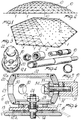
- Fig. 1 is a schematic view of the structure according to the invention during the assembly phase, on a pneumatic seal membrane, on a plane before the erection to produce a preferred dome-like geometry, in this case with an hexagonal base;
- Fig. 2 shows a schematic prospect of a dome with reticular spatial structure, according to the invention;
- Fig. 3 is a schematic exploded perspective view of a connecting node;
Fig. 4 is an exploded perspective view of a variable-length rod-like element; - Fig. 5 is a view of an automatic locking means;
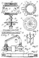
- Fig. 6 is a diametral cross section view of a connecting node comprising the rocker supporting apparatus for the membrane and with the end of a rod-like element applied;
- Fig. 7 is an exploded cross section view of a connecting node;
- Fig. 8 is a plan view, in partial cross section, of a connecting node;
- Fig. 9 is a view of a connecting node from the opposite side;
- Fig. 10 is a schematic perspective view of a plinth for anchoring a perimetral node to the foundations;
- Fig. 11 is a cross section view of a perimetral node coupled to said plinth;
- Fig. 12 is a partial cross section view of a perimetral rod-like element;
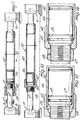
- Fig. 13 is a cross section view of a variable-length rod-like element before its extension in length;
- Fig. 14 is a cross section view of a rod-like element once it has reached its preset working length;
- Figs. 15 and 16 are enlarged scale views of the locking means respectively before and after the extension has occurred;
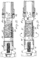
- Fig. 17 is an exploded perspective view of another aspect of the rod-like element with variable working length;
- Fig. 18 is a detailed view of the rod-like element illustrating the locking means during their action phase;
- Fig. 19 is a view of the locking means once the locking has occurred;
- Figs. 20 and 21 are views of the attachment body of the rod-like elements with a device for performing the final extension.
- With reference to the above described figures, the pneumatically erected reticular spatial structure, according to the invention, comprises a plurality of perimetral rod-like elements, indicated by 1, which advantageously but not necessarily are of the fixed-length type, and at their ends are coupled to perimetral nodes, generally indicated by the
reference numeral 2, after arranging thelower plates 12a on the resting plane according to the preset geometry. - As schematically indicated in Fig. 1, the structure is arranged on a base plane on a
membrane 13, anchored peripherally to the pneumatically sealed foundations, arranging the rod-like elements 1 according to a geometrical pattern provided by the project and connecting them to the perimetral nodes. - The reticular structure, according to the invention, furthermore comprises variable-length rod-like elements, generally indicated by the
reference numeral 10 which also, at their ends, are articulated to connectingnodes 11 with the possibility of rotating about their own axis of rotation with respect to the geometrical center of said connecting nodes; furthermore, part of the rod-like elements 10 are articulated also to theperimetral nodes 2, so as to create, in practice, a plane grid applied both to themembrane 13, at selected points, and to the perimetral foundation plinths. - As illustrated in detail in Fig. 6 and in the subsequent figures, the entire apparatus of the connecting
node 11 is provided with alower plate 12a and with anupper plate 12b securing themembrane 13 between themselves by means of a threaded connectingpivot 14 suspended, rocker-like, from the node. - For the sake of descriptive completeness, it should be furthermore added that the
plates membrane 13, with annular recesses, indicated by 15, which facilitate the adhesion of the membrane to the plates, in order to ensure a waterproof connection. - The
pivot 14 is suspended from the hollow body, indicated by 20, which is substantially composed of alower base 21 and of anupper base 22 connected to a wall having the inner and outer surfaces shaped according to concentric spherical surfaces. - The
lower base 21 defines, in the region of coupling to thepivot 14, acoupling seat 25 shaped like a spherical portion, in which a complementarilyshaped nut 26 engages and allows a variable positioning of thehollow body 20 with respect to thepivot 14. - It should be furthermore added that a
ring 26 of elastically deformable material is interposed between thelower base 21 and the upper plate 12 and acts as a shock absorber, absorbing part of the vibrations transmitted by the membrane to the metallic structure. - A plurality of
openings 30 is provided on thewall 23 for the passage of thelocking bolts 34 required to lock the ends of the rod-like elements 10. For this purpose, the rod-like elements 10 are provided with aterminal body 31 which defines aspherical seat 32 in the region of coupling to thewall 23 which has a curvature matching the curvature of the node spherical surface, so as to achieve a stable coupling also when the angle of the terminal body with respect to the node varies. - Similarly, inside the hollow body 20 a
shaped body 33 is provided which has a spherical configuration in the region of contact to the inner surface, so as to ensure a perfect coupling also of the surfaces in contact inside the node, as the angle of incidence of the terminal body with respect to the node varies. - The
upper base 22 is screwed to thehollow body 20 so as to be removable and to permit access to thebolts 34 for the final locking in the preset position of the various rod-like elements once their extension is completed to reach the preset length after the structure has been erected. - The structure can be raised, as previously mentioned, by pneumatic means, but conceptually nothing varies if it is raised by means different from pneumatic ones, such as, for example, by means of cables, jacks or other mechanical systems.
- The various variable-length rod-
like elements 10 have a tubular body, indicated by 40, which, at least at one end, defines a threadedportion 41 with which aring nut 42 engages. Thering nut 42 is provided with anabutment 43, which, in cooperation with the end of thetubular body 40, defines thesnap coupling seat 44 for a locking means which is advantageously constituted by a splitelastic ring 45 housed in a piston-like body 46 which is slideable within thetubular body 10. Theelastic ring 45 is positioned on thebody 46 on the opposite side with respect to theterminal body 31. - A threaded
portion 47 is provided in the region of coupling between thepiston body 46 and theterminal body 31, and alocking nut 48 is engaged therein once the desired extension has been performed. - In practice, as is better illustrated in Figs. 13 and 14, in assembly conditions the piston-
like body 46 is housed in thetubular body 40 and supports theelastic ring 45. - Once the the rod-like element has been extended following the raising of the structure pneumatically or by other means, the ring locks in the
coupling seat 44 defined by theabutment 43 and by the end of thetubular body 40 thus preventing any further axial motion of the tubular body with respect to the piston-like body. - In Figs. 17, 18 and 19, it is illustrated a rod-like element with variable working length, according to another aspect of the invention.
- In practice, an outer
tubular body 60 has, at one of its ends, an outer threadedportion 61 engaging asleeve 62 which inwardly defines anabutment 63 delimitating, with the end of the outertubular body 60, aseat 64 in which splitelastic rings 65 are provided acting in compression. On theelastic rings 65 act the threadedmeans 66 arranged outside thesleeve 62 to radially compress therings 65. - An inner
tubular body 70 is accommodated inside thetubular body 60 and defines a piston-like portion 71 providing alocking seat 72 in which saidelastic rings 65 are locked to prevent the reentry of the innertubular body 70 once it has been extended to the preset length. - In some cases, it may happen that the rod-like elements cannot extend completely to reach the preset length, so that the elastic locking rings do not insert in the related seat; to make this insertion possible in any case, a device for performing the final extension can be provided as illustrated in figs. 20 and 21.
- Such a device comprises a threaded
sleeve 80 which is connected to theterminal body 81 and engages rotatably with a threadedportion 83 defined by thetubular element 82. - The threaded
sleeve 80 is provided with adiametral hole 84 which is engageable by a tool to rotate the sleeve so as to "pull" thetubular element 82 until the snap-together coupling of the elastic rings is achieved. - Furthermore, an element for locking the reentry of the
tubular element 82 is provided, which consists of adiametral body 85 diametrally supported by thetubular element 82. Thebody 85 has a minimum length such as to be included in the dimensions of thetubular element 82 and is extendable to engage in abutment with the sleeve provided on the outer tubular element. For this purpose, thebody 85 is composed of a first part 85a and of asecond part 85b with a mutual coupling of the bolt-threaded seat type. - It should be furthermore added that the
perimetral nodes 2 can be made similar to thenodes 11, assembling them in such a way as to make them capable of oscillating in order to assume the correct position, or possibly ahollow body 20 can be fixed with a preset inclination to anupper base plate 50 which, by means of thelocking tension elements 51, locks onto alower base plate 52 which can be connected to a plinth for anchoring to the ground or to the perimetral foundation ridge. - In practice, in the assembly, after arranging the
suspension plates 12a on the resting plane, a plane reticular structure is applied to amembrane 13 which is peripherally anchored and pneumatically sealed, by connecting to one another the perimetral nodes of the foundations of the rod-like elements 1, as well as variable-length rod-like elements 10 to the connecting nodes, according to a preset pattern, then air is forced below the membrane, performing the gradual raising, which, as already mentioned above, can also be achieved with different means. - During the raising of the structure, the rod-
like elements 10 extend and rotate both about their own axis and about the various geometrical centers of the connecting nodes until, once the preset working length has been reached the rod-like elements lock at the set position. - Once the desired structural configuration has been achieved, the ring nuts of the locking nuts and of the various rod-like elements are tightened, and then the rod-like elements are locked with respect to the nodes by using the
bolt 14 which can be reached from the interior of thehollow body 20, thus achieving also the locking at all the nodes. - From what has been described, it can be seen that the invention achieves the proposed aims, and in particular the fact is stressed that the reticular structure, according to the invention, has a remarkably easy assembly, due to the presence of components similar to one another, composed of nodes and variable-length rod-like elements, which have the possibility of reaching a preset length during the pneumatic raising.
- Moreover, the system makes it possible to release quickly the various lockings in order to recover the elements at a substantially plane level, preferably through a pneumatic disassembly.
- It is furthermore specified that the variable-length rod-like elements can be provided, according to the requirements, either with both ends extendable or with one fixed end and with one extendable end.
- It has been furthermore observed that it is possible to use a limited variety of rod-like elements since the various rod-like elements all have the same central portion constituted either by the
tubular body 40 or by the outertubular body 60 and, according to the working length needed, just the length of theterminal body 31 has to be modified. - The invention thus conceived is susceptible to numerous modifications and variations, all of which are within the scope of the inventive concept.
- Moreover, all the details may be replaced with technically equivalent elements.
- In practice, the materials employed, so long as compatible with the specific use, as well as the dimensions and the contingent shapes, may be any according to the requirements.
Claims (14)
Priority Applications (1)
| Application Number | Priority Date | Filing Date | Title |
|---|---|---|---|
| AT87107596T ATE72469T1 (en) | 1986-06-05 | 1987-05-25 | RETICULAR SPATIAL STRUCTURE. |
Applications Claiming Priority (2)
| Application Number | Priority Date | Filing Date | Title |
|---|---|---|---|
| IT2068786 | 1986-06-05 | ||
| IT20687/86A IT1190044B (en) | 1986-06-05 | 1986-06-05 | SPATIAL RETICULAR STRUCTURE MADE UP OF TELESCOPIC EXTENSIBLE MODULAR ELEMENTS AND CONTAINED WITH SPHERICAL HINGE KNOTS |
Publications (3)
| Publication Number | Publication Date |
|---|---|
| EP0248317A2 EP0248317A2 (en) | 1987-12-09 |
| EP0248317A3 EP0248317A3 (en) | 1990-05-30 |
| EP0248317B1 true EP0248317B1 (en) | 1992-02-05 |
Family
ID=11170577
Family Applications (1)
| Application Number | Title | Priority Date | Filing Date |
|---|---|---|---|
| EP87107596A Expired - Lifetime EP0248317B1 (en) | 1986-06-05 | 1987-05-25 | Reticular spatial structure |
Country Status (13)
| Country | Link |
|---|---|
| US (1) | US4796389A (en) |
| EP (1) | EP0248317B1 (en) |
| JP (1) | JPS6335978A (en) |
| AT (1) | ATE72469T1 (en) |
| AU (1) | AU597377B2 (en) |
| CA (1) | CA1287961C (en) |
| DE (1) | DE3776593D1 (en) |
| ES (1) | ES2030677T3 (en) |
| IL (1) | IL82707A0 (en) |
| IT (1) | IT1190044B (en) |
| NZ (1) | NZ220552A (en) |
| SU (1) | SU1570655A3 (en) |
| ZA (1) | ZA874051B (en) |
Families Citing this family (21)
| Publication number | Priority date | Publication date | Assignee | Title |
|---|---|---|---|---|
| FR2628461B1 (en) * | 1988-03-14 | 1991-09-13 | Overbeeke Daniel | MULTIDIMENSIONAL LATTICE CONSTRUCTION BAR |
| JP2750278B2 (en) * | 1995-04-19 | 1998-05-13 | 小川テント株式会社 | Truss construction joint and truss construction joint unit |
| GB2300240A (en) * | 1995-04-25 | 1996-10-30 | Bailey Ralph Peter Steven | Constructional system |
| US6065263A (en) * | 1997-06-27 | 2000-05-23 | Kaieitechno Co., Ltd. | Connecting structure for concrete block and connector used therefor |
| US5996288A (en) * | 1997-10-20 | 1999-12-07 | Aiken; Ernest G | Geodesic domes and improved joints therefor |
| GB0003085D0 (en) * | 2000-02-10 | 2000-03-29 | Peter Dann Limited | Arch structure |
| US20090113816A1 (en) * | 2002-03-15 | 2009-05-07 | Jean-Christophe Jacques Kling | Architectural system using a retractable strut aligned in a base plane and an extension strut protruding acutely from the base plane |
| US6887009B1 (en) | 2002-10-01 | 2005-05-03 | Conservatek Industries, Inc. | Cylindrical joint and reticulated frame structure |
| US7921613B2 (en) * | 2008-06-11 | 2011-04-12 | Koichi Paul Nii | Terraced structured land joint and assembly system |
| DE202009000481U1 (en) * | 2009-01-13 | 2010-06-02 | B.T. Innovation Gmbh | Turnbuckle for precast concrete parts |
| JP5500913B2 (en) * | 2009-08-27 | 2014-05-21 | 新日鉄住金エンジニアリング株式会社 | Node structure of lattice shell structure and its construction method |
| JP5489600B2 (en) * | 2009-08-27 | 2014-05-14 | 新日鉄住金エンジニアリング株式会社 | Node structure of lattice shell structure and its construction method |
| JP2010229811A (en) * | 2010-06-16 | 2010-10-14 | Glenn A Reynolds | Coaxial joint system |
| CN102995748B (en) * | 2012-12-06 | 2015-01-14 | 北京工业大学 | Pneumatic membrane compression bar and manufacturing method thereof |
| EP2921600B1 (en) * | 2014-03-19 | 2016-05-18 | Airbus Operations GmbH | Rotary joint, framework construction kit and method for constructing a framework |
| US20170159280A1 (en) * | 2014-08-15 | 2017-06-08 | Kenneth E. Nunn | Construction and hub structures therefrom |
| EP3098463B1 (en) * | 2015-05-26 | 2018-03-14 | Airbus Operations GmbH | Rotary joint, framework construction kit and method for manufacturing a rotary joint |
| EP3135833B1 (en) * | 2015-08-27 | 2019-05-08 | Airbus Operations GmbH | Rotary joint, framework construction kit, framework with rotary joints and method for manufacturing a rotary joint |
| ES2659841A1 (en) * | 2018-01-11 | 2018-03-19 | Universidad Politécnica de Madrid | TRANSFORMABLE RETICULAR STRUCTURE |
| TWI770599B (en) * | 2020-09-04 | 2022-07-11 | 賴祥瑞 | Modular connection device |
| CN113389277B (en) * | 2021-03-15 | 2023-07-11 | 中国水利水电第九工程局有限公司 | Construction method for building roof with double-layer steel structure net rack composite membrane structure |
Family Cites Families (9)
| Publication number | Priority date | Publication date | Assignee | Title |
|---|---|---|---|---|
| US3006670A (en) * | 1959-06-02 | 1961-10-31 | Goodyear Aircraft Corp | Frame for supporting domed structures |
| US3129531A (en) * | 1961-11-14 | 1964-04-21 | Connor Robert | Reinforced building structure |
| US3973370A (en) * | 1972-05-22 | 1976-08-10 | Mcallister Jack G | Method of making a frame assembly |
| US3918233A (en) * | 1973-02-27 | 1975-11-11 | Harold Graves Simpson | Construction system |
| US4296585A (en) * | 1978-05-30 | 1981-10-27 | Dante Bini | Permanent weather covers |
| EP0070096A3 (en) * | 1981-07-14 | 1983-05-11 | Norman Ashley Boyce | Rigid building frame with inflatable member |
| DE8123976U1 (en) * | 1981-08-17 | 1982-02-04 | Mero-Raumstruktur GmbH & Co Würzburg, 8700 Würzburg | KIT FOR THE PRODUCTION OF A ROOF SKIN TO BE ASSEMBLED FROM INDIVIDUAL PLATE-SHAPED ROOF ELEMENTS |
| ZA834078B (en) * | 1982-03-05 | 1984-01-23 | ||
| US4669909A (en) * | 1984-03-02 | 1987-06-02 | Galan Inchaurbe Jose M | Spacial structure |
-
1986
- 1986-06-05 IT IT20687/86A patent/IT1190044B/en active
-
1987
- 1987-05-25 DE DE8787107596T patent/DE3776593D1/en not_active Expired - Fee Related
- 1987-05-25 EP EP87107596A patent/EP0248317B1/en not_active Expired - Lifetime
- 1987-05-25 AT AT87107596T patent/ATE72469T1/en not_active IP Right Cessation
- 1987-05-25 ES ES198787107596T patent/ES2030677T3/en not_active Expired - Lifetime
- 1987-05-29 IL IL82707A patent/IL82707A0/en not_active IP Right Cessation
- 1987-06-01 US US07/055,955 patent/US4796389A/en not_active Expired - Fee Related
- 1987-06-03 CA CA000538680A patent/CA1287961C/en not_active Expired - Lifetime
- 1987-06-04 AU AU73846/87A patent/AU597377B2/en not_active Ceased
- 1987-06-04 JP JP62139075A patent/JPS6335978A/en active Pending
- 1987-06-04 NZ NZ220552A patent/NZ220552A/en unknown
- 1987-06-05 ZA ZA874051A patent/ZA874051B/en unknown
- 1987-06-05 SU SU874202721A patent/SU1570655A3/en active
Also Published As
| Publication number | Publication date |
|---|---|
| SU1570655A3 (en) | 1990-06-07 |
| EP0248317A2 (en) | 1987-12-09 |
| US4796389A (en) | 1989-01-10 |
| CA1287961C (en) | 1991-08-27 |
| IT1190044B (en) | 1988-02-10 |
| ES2030677T3 (en) | 1992-11-16 |
| JPS6335978A (en) | 1988-02-16 |
| EP0248317A3 (en) | 1990-05-30 |
| AU7384687A (en) | 1987-12-10 |
| IT8620687A1 (en) | 1987-12-05 |
| IT8620687A0 (en) | 1986-06-05 |
| IL82707A0 (en) | 1987-11-30 |
| ATE72469T1 (en) | 1992-02-15 |
| AU597377B2 (en) | 1990-05-31 |
| DE3776593D1 (en) | 1992-03-19 |
| ZA874051B (en) | 1988-02-24 |
| NZ220552A (en) | 1990-04-26 |
Similar Documents
| Publication | Publication Date | Title |
|---|---|---|
| EP0248317B1 (en) | Reticular spatial structure | |
| CA1125982A (en) | Permanent weather covers | |
| CA1269585A (en) | Hub and strut-endcap assembly for tent frame struts | |
| AU603861B2 (en) | Node member for use in building a geodesic structure | |
| US3059658A (en) | Shelter framework | |
| US5423341A (en) | Unitized foldable tent frame | |
| US2962034A (en) | Shelter and method of making same | |
| US6345638B1 (en) | Multiple peak cable tent | |
| US4353662A (en) | Construction system for reticulated steel structures | |
| NO165152B (en) | THREE-DIMENSIONAL TRAINING. | |
| AU674258B2 (en) | Emergency shelter | |
| US5566516A (en) | Spherical grid | |
| WO1994024380A9 (en) | Emergency shelter | |
| CN219834046U (en) | Wind-resistant photovoltaic support | |
| WO1996025572A2 (en) | Inflatable roof support systems | |
| GB2192965A (en) | Space frame system | |
| US4190990A (en) | Frame assembly | |
| US9151035B2 (en) | Double axis frame strut | |
| SU1753953A3 (en) | Assembly joint of bars of three-dimensional skeleton | |
| US2359683A (en) | Horizontal tank and support therefor | |
| CH642130A5 (en) | Process for forming a dome-shaped spatial roof and reticular structure for effecting said process | |
| WO2000026544A1 (en) | Improvements relating to temporary structures | |
| JP3250325U (en) | Dome tent frame | |
| CN215170198U (en) | Underground fan-shaped air barrier framework | |
| US3393480A (en) | Antenna supporting tower and method of constructing same |
Legal Events
| Date | Code | Title | Description |
|---|---|---|---|
| PUAI | Public reference made under article 153(3) epc to a published international application that has entered the european phase |
Free format text: ORIGINAL CODE: 0009012 |
|
| AK | Designated contracting states |
Kind code of ref document: A2 Designated state(s): AT CH DE ES FR GB IT LI |
|
| PUAL | Search report despatched |
Free format text: ORIGINAL CODE: 0009013 |
|
| AK | Designated contracting states |
Kind code of ref document: A3 Designated state(s): AT CH DE ES FR GB IT LI |
|
| RHK1 | Main classification (correction) |
Ipc: E04B 1/19 |
|
| 17P | Request for examination filed |
Effective date: 19900620 |
|
| 17Q | First examination report despatched |
Effective date: 19910326 |
|
| GRAA | (expected) grant |
Free format text: ORIGINAL CODE: 0009210 |
|
| AK | Designated contracting states |
Kind code of ref document: B1 Designated state(s): AT CH DE ES FR GB IT LI |
|
| PG25 | Lapsed in a contracting state [announced via postgrant information from national office to epo] |
Ref country code: AT Effective date: 19920205 |
|
| REF | Corresponds to: |
Ref document number: 72469 Country of ref document: AT Date of ref document: 19920215 Kind code of ref document: T |
|
| REF | Corresponds to: |
Ref document number: 3776593 Country of ref document: DE Date of ref document: 19920319 |
|
| ET | Fr: translation filed | ||
| ITF | It: translation for a ep patent filed | ||
| REG | Reference to a national code |
Ref country code: ES Ref legal event code: FG2A Ref document number: 2030677 Country of ref document: ES Kind code of ref document: T3 |
|
| PLBE | No opposition filed within time limit |
Free format text: ORIGINAL CODE: 0009261 |
|
| STAA | Information on the status of an ep patent application or granted ep patent |
Free format text: STATUS: NO OPPOSITION FILED WITHIN TIME LIMIT |
|
| 26N | No opposition filed | ||
| PGFP | Annual fee paid to national office [announced via postgrant information from national office to epo] |
Ref country code: GB Payment date: 19940503 Year of fee payment: 8 |
|
| PGFP | Annual fee paid to national office [announced via postgrant information from national office to epo] |
Ref country code: CH Payment date: 19940919 Year of fee payment: 8 |
|
| PGFP | Annual fee paid to national office [announced via postgrant information from national office to epo] |
Ref country code: ES Payment date: 19940927 Year of fee payment: 8 Ref country code: DE Payment date: 19940927 Year of fee payment: 8 |
|
| PGFP | Annual fee paid to national office [announced via postgrant information from national office to epo] |
Ref country code: FR Payment date: 19940929 Year of fee payment: 8 |
|
| PG25 | Lapsed in a contracting state [announced via postgrant information from national office to epo] |
Ref country code: GB Effective date: 19950525 |
|
| PG25 | Lapsed in a contracting state [announced via postgrant information from national office to epo] |
Ref country code: ES Free format text: LAPSE BECAUSE OF NON-PAYMENT OF DUE FEES Effective date: 19950526 |
|
| PG25 | Lapsed in a contracting state [announced via postgrant information from national office to epo] |
Ref country code: LI Effective date: 19950531 Ref country code: CH Effective date: 19950531 |
|
| GBPC | Gb: european patent ceased through non-payment of renewal fee |
Effective date: 19950525 |
|
| REG | Reference to a national code |
Ref country code: CH Ref legal event code: PL |
|
| PG25 | Lapsed in a contracting state [announced via postgrant information from national office to epo] |
Ref country code: DE Effective date: 19960201 |
|
| PG25 | Lapsed in a contracting state [announced via postgrant information from national office to epo] |
Ref country code: FR Effective date: 19960229 |
|
| REG | Reference to a national code |
Ref country code: FR Ref legal event code: ST |
|
| REG | Reference to a national code |
Ref country code: FR Ref legal event code: ST |
|
| REG | Reference to a national code |
Ref country code: ES Ref legal event code: FD2A Effective date: 19990201 |
|
| PG25 | Lapsed in a contracting state [announced via postgrant information from national office to epo] |
Ref country code: IT Free format text: LAPSE BECAUSE OF NON-PAYMENT OF DUE FEES;WARNING: LAPSES OF ITALIAN PATENTS WITH EFFECTIVE DATE BEFORE 2007 MAY HAVE OCCURRED AT ANY TIME BEFORE 2007. THE CORRECT EFFECTIVE DATE MAY BE DIFFERENT FROM THE ONE RECORDED. Effective date: 20050525 |