EP0248094B1 - Vorrichtung zum Unterstützen eines Körpers zur Hin- und Herbewegung - Google Patents
Vorrichtung zum Unterstützen eines Körpers zur Hin- und Herbewegung Download PDFInfo
- Publication number
- EP0248094B1 EP0248094B1 EP19860107296 EP86107296A EP0248094B1 EP 0248094 B1 EP0248094 B1 EP 0248094B1 EP 19860107296 EP19860107296 EP 19860107296 EP 86107296 A EP86107296 A EP 86107296A EP 0248094 B1 EP0248094 B1 EP 0248094B1
- Authority
- EP
- European Patent Office
- Prior art keywords
- ram
- roller
- reciprocal movement
- contact
- planar
- Prior art date
- Legal status (The legal status is an assumption and is not a legal conclusion. Google has not performed a legal analysis and makes no representation as to the accuracy of the status listed.)
- Expired
Links
- 238000013016 damping Methods 0.000 claims description 9
- 238000012856 packing Methods 0.000 claims description 8
- 101100328887 Caenorhabditis elegans col-34 gene Proteins 0.000 description 16
- 239000004809 Teflon Substances 0.000 description 3
- 229920006362 Teflon® Polymers 0.000 description 3
- 238000005096 rolling process Methods 0.000 description 3
- 229920000742 Cotton Polymers 0.000 description 2
- 239000011152 fibreglass Substances 0.000 description 2
- 238000000034 method Methods 0.000 description 2
- 238000010409 ironing Methods 0.000 description 1
- 238000004519 manufacturing process Methods 0.000 description 1
- 238000005555 metalworking Methods 0.000 description 1
- 230000036316 preload Effects 0.000 description 1
- 125000006850 spacer group Chemical group 0.000 description 1
Images

Classifications
-
- B—PERFORMING OPERATIONS; TRANSPORTING
- B21—MECHANICAL METAL-WORKING WITHOUT ESSENTIALLY REMOVING MATERIAL; PUNCHING METAL
- B21D—WORKING OR PROCESSING OF SHEET METAL OR METAL TUBES, RODS OR PROFILES WITHOUT ESSENTIALLY REMOVING MATERIAL; PUNCHING METAL
- B21D22/00—Shaping without cutting, by stamping, spinning, or deep-drawing
- B21D22/20—Deep-drawing
-
- F—MECHANICAL ENGINEERING; LIGHTING; HEATING; WEAPONS; BLASTING
- F16—ENGINEERING ELEMENTS AND UNITS; GENERAL MEASURES FOR PRODUCING AND MAINTAINING EFFECTIVE FUNCTIONING OF MACHINES OR INSTALLATIONS; THERMAL INSULATION IN GENERAL
- F16F—SPRINGS; SHOCK-ABSORBERS; MEANS FOR DAMPING VIBRATION
- F16F7/00—Vibration-dampers; Shock-absorbers
Definitions
- the invention relates to a machine for forming can bodies, said machine comprising a ram supported by a frame for reciprocal movement along a horizontal path, said ram being provided with support surfaces, said surfaces being circumferentially spaced apart from each other.
- a typical method manufacturing two piece cans consists of making a circular blank and then drawing the blank to form a shallow cup. The cup is fed in position ahead of a punch attached to the ram, and then is formed by the ram through a redraw die and a plurality of ironing dies located in a tool pack housing.
- Presses for directing the movement of the ram may be either mechanical or hydraulic.
- Exemplary of mechanical type machines are the machines described in US-A-3 696 675 as mentioned above and entitled “Metal Working Crank and Slide Press Mechanism” as well as in US-A-3 702 559 entitled “Can Body Making Machine”.
- the can body making machine according to US-A-3 702 559 is constructed such that the ram slides on guides with an attached cam follower cooperating with cam grooves on a barrel cam.
- the barrel cam is mounted on a shaft driven by an electric motor.
- the ram is mounted on a carriage, and the support surfaces mentioned in the beginning are cylindrical surfaces of wheels which are mounted in the carriage and which run on the top and bottom surfaces of hardened way strips.
- the wheels can be adjusted with a predetermined amount of preload to avoid slack in the wheels.
- the carriage is driven by a crank and connecting rod attached to a parallel motion assembly.
- Such mechanically driven rams can be driven at high speeds but do not always provide uniform punch speed or travel in a straight line motion, which is critical to continuously producing uniform can walls.
- a machine of the type mentioned in the beginning for forming can bodies which machine is characterized in that said support surfaces comprise at least two planar surfaces extending in a direction parallel to the longitudinal axis of said ram, a ram cradle assembly is provided comprising at least two supporting means spaced apart in the longitudinal direction of the ram, each supporting means comprising roller means mounted to said frame, said roller means being in contact with each of said spaced apart planar surfaces, each roller means being mounted for rotation, damping means are affixed to the frame and in contact with the outer surface of said ram during its reciprocal movement along the horizontal path, said damping means being positioned between said roller means and the end of said ram to which can forming apparatus is attached; at least one freely rotable roller secured to the frame and having a generally cylindrical outer surface, a third planar surface on said ram extending in a direction parallel to said longitudinal axis, and means for ensuring contact pressure between said freely rotable roller and said third planar surface,
- the invention provides means for supporting a reciprocal ram used in a machine for forming can bodies.
- the invention also provides means for damping vibrations so as to limit damage to the apparatus normally resulting from such vibrations. Also, by minimizing vibrations, the can making efficiency is increased.
- the ram has an outer surface shaped to cooperate with angularly related surfaces on the ram cradle assembly.
- the ram cradle assembly comprises at least two supporting means wherein each supporting means comprises two angularly related rollers having generally cylindrical surfaces.
- the ram is provided with two angularly related planar surfaces extending in a direction generally parallel to the longitudinal axis of the ram.
- the angular relationship of the planar surfaces is the same as the angular relationship of the rollers so that the ram may be supported by the ram cradle assembly with the planar surfaces on the ram in contact with the cylindrical surfaces of the rollers.
- the weight of the ram is generally sufficient to ensure that the ram remains in contact with the rollers.
- This force applying means comprises at least two spaced apart rollers, each of which has a generally cylindrical surface.
- the ram is provided with another planar surface extending in a direction generally parallel to the longitudinal axis of the ram and located so that it will be contacted by the force applying rollers. Any means, such as a spring, may be used to apply the force to the force applying rollers.
- the damping means in the preferred embodiment of the invention, comprises a rope packing that is supported on the ram cradle assembly and is in circumferential contact with the adjacent portions of the outer surface of the ram.
- the preferred rope packing comprises Teflon (trademark of E. I. DuPont) coated cotton or fiberglass rope.
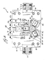
- a ram cradle assembly 2 which, in the preferred embodiment of the invention, is mounted on the frame 3.
- the end portion (not shown) of the ram 4 extending beyond roller 38 in Fig. 1 is connected to means for imparting straight line reciprocating motion.
- the end portion (not shown) of the ram 4 extending beyond roller 40 in Fig. 1 is connected to means for forming cans. While the preferred embodiment is illustrated for use in a machine for forming can bodies, the concepts of this invention may also be used with any mechanism wherein a body needs to be supported so that the body can be reciprocated in a horizontal direction at various rates of reciprocation, such as hundreds of times per minute.
- the ram cradle assembly 2 comprises support plates 10 and 12 which extend between rails 6 and 8 and are secured to each rail 6, 8 by suitable means such as the threaded bolts 14.
- a plurality of spacer blocks 16 extend between the support plates 10 and 12 and are secured in place by threaded bolts 18.
- a pair of freely rotatable support rollers 20 and 22 having angularly related generally cylindrical surfaces 24 and 26 are mounted in recesses in each of the plates 10 and 12 and secured thereto by suitable means such as bolts (not shown).
- the rollers 20 and 22 are mounted between a pair of spaced apart lugs 28 and held in position by nuts 30.
- the ram 4 is provided with two angularly related planar surfaces 32 and 34, each of which extends in a direction generally parallel to the longitudinal axis of the ram 4.
- An opening 36 is provided in each of the plates 10 and 12 to provide for the passage of the ram 4 through the plates 10 and 12.
- the ram 4 is supported on the rollers 20 and 22 so that the planar surface 32 is in contact with and supported by generally cylindrical surface 24 and the planar surface 34 is in contact with and supported by generally cylindrical surface 26.
- the weight of the ram 4 cooperates with the anular relationship of the planar surfaces 32 and 34 and the angular relationship of the generally cylindrical surfaces 24 and 26 to retain the longitudinal axis to the ram 4 from movement in any direction perpendicular to the longitudinal axis during the reciprocal movement of the ram 4.
- only two rollers 20, 22 and two planar surfaces 32, 34 are illustrated in Fig. 2, it is to be understood that more than two rollers and two planar surfaces may be used.
- the angular relationship of the planar surfaces 32, 34 corresponds to the angular relationship of the generally cylindrical surfaces 24, 26 of the rollers 20, 22.
- the weight of the ram 4 is sufficient to hold it in position during the reciprocal movement.
- each of rollers 38 and 40 comprises a dovetailed recess 46 in each of the plates 10 and 12 and a corresponding dovetailed projection 48 on a support member 50 which depends from a plate member 52 which is secured to each plate 10 and 12 by threaded bolts 54.
- the support member 50 has two spaced apart projecting portions 56 each of which is provided with a vertically extending recess 58.
- the rollers 38 and 40 are mounted in bearing blocks 60 which have projection portions 62 mounted for sliding movement in the recesses 58.
- the relationship between the bearing blocks 60 and the recesses 58 is such so as to allow movement of the bearing blocks 60 in a vertical direction but to prevent relative movement in a horizontal direction.
- the upper portion of the bearing block 60 is attached to the lower portion of a spring 64.
- the upper portion of the spring 64 is attached to a plate 66, having a threaded member 68 projecting therefrom and extending through an opening in the plate member 52.
- a nut 70 is threaded on the member 68 so that the tension of the spring 64 may be adjusted.
- the ram 4 is provided with a planar surface 72 and, as illustrated in Fig.
- rollers 38 and 40 are in contact with the generally cylindrical surfaces 42 and 44 of the rollers 38 and 40.
- the springs 64 function to maintain the rollers 38 and 40 in contact with the planar surface 72 and to apply an additional force in the ram 4 to ensure the desired rolling relationship between the planar surfaces and the generally cylindrical surfaces.
- the amount of force applied by rollers 38 and 40 is controlled by adjustment of the springs 64.
- the ram 4 is reciprocated at rates of hundreds of times per minute.
- damping means are provided.
- the damping means comprise a rope packing 74 in contact with the outer surface of the ram 4.
- the rope packing 74 is mounted in a holder 76 secured to a plate 78 mounted in spaced relationship to the plate 12 by spacing means 80.
- a packing push plate 82 is mounted on the holder 76 by threaded bolts 84.
- the rope packing 74 is a conventional half and half rope packing formed from Teflon coated cotton or fiberglass (Teflon is a trademark of E. I. DuPont).
Landscapes
- Engineering & Computer Science (AREA)
- Mechanical Engineering (AREA)
- General Engineering & Computer Science (AREA)
- Transmission Devices (AREA)
- Presses And Accessory Devices Thereof (AREA)
- Advancing Webs (AREA)
Claims (3)
- Maschine zum Formen von Dosenkörpern, wobei die Mschine einen Stempel (4) umfaßt, der mittels eines Rahmens (3) zur Hin- und Herbewegung längs eines horizontalen Wegs gehaltert ist, wobei der Stempel (4) mit Auflageflächen (32, 34) versehen ist, welche Flächen (32, 34) umfangsmäßig im Abstand voneinander angeordnet sind, dadurch gekennzeichnet, daß die Auflageflächen (32, 34) wenigstens zwei planare Oberflächen (32, 34) umfassen, die sich in einer Richtung parallel zu der Längsachse des Stempels (4) erstrecken, wobei eine Stempellagerstuhlanordnung (2) vorgesehen ist, die wenigstens zwei Halteeinrichtungen (10, 12) umfaßt, welche in der Längsrichtung des Stempels (4) im Abstand voneinander angeordnet sind, wobei jede Halteeinrichtung (10, 12) eine Rolleneinrichtung (20, 22) umfaßt, die an dem Rahmen (3) angebracht ist, wobei die Rolleneinrichtung (20, 22) in Kontakt mit jeder der im Abstand voneinander angeordneten planaren Oberflächen (32, 34) ist, wobei jede Rolleneinrichtung (20, 22) zur Drehung angebracht ist, wobei eine Dämpfungseinrichtung (74) an dem Rahmen (3) befestigt und in Kontakt mit der äußeren Oberfläche des Stempels (4) während dessen Hin- und Herbewegung längs des horizontalen Wegs ist, wobei die Dämpfungseinrichtung (74) zwischen der Rolleneinrichtung (20, 22) und dem Ende des Stempels (4), an welchem die Dosenformungseinrichtung angebracht ist, positioniert ist; wobei wenigstens eine frei drehbare Rolle (38, 40) an dem Rahmen (3) befestigt ist und eine generell zylindrische äußere Oberfläche (42, 44) hat, wobei sich eine dritte planare Oberfläche (72) in dem Stempel (4) in einer Richtung parallel zu der Längsachse erstreckt, und wobei eine Einrichtung (60, 64, 66, 68) zum Sicherstellen eines Kontaktdrucks zwischen der frei drehbaren Rolle (38, 40) und der dritten planaren Oberfläche (72) vorgesehen ist, so daß dadurch ein Kontaktdruck zwischen dem Stempel (4) und der Rolleneinrichtung (20, 22) während der Hin- und Herbewegung des Stempels (4) vorgesehen wird.
- Einrichtung nach Anspruch 1, dadurch gekennzeichnet, daß die Dämpfungseinrichtung (74) eine Seilpackung umfaßt, die innerhalb einer Halteeinrichtung (76) zum Kontakt mit der äußeren Oberfläche des Stempels (4) angebracht ist.
- Einrichtung nach Anspruch 1, dadurch gekennzeichnet, daß die Einrichtung (60, 64, 66, 68) zum Drängen der einen frei drehbaren Rolle (38, 40) eine Federeinrichtung (64) zum Anwenden einer Kraft auf die Rolle (38, 40), so daß dadurch die Rolle (38, 40) gegen die dritte planare Oberfläche (72) gedrängt wird, umfaßt.
Priority Applications (3)
| Application Number | Priority Date | Filing Date | Title |
|---|---|---|---|
| US06/818,406 US4614104A (en) | 1984-08-27 | 1986-01-13 | Apparatus for supporting a body for reciprocal movement |
| EP19860107296 EP0248094B1 (de) | 1986-05-28 | 1986-05-28 | Vorrichtung zum Unterstützen eines Körpers zur Hin- und Herbewegung |
| DE8686107296T DE3680913D1 (de) | 1986-05-28 | 1986-05-28 | Vorrichtung zum unterstuetzen eines koerpers zur hin- und herbewegung. |
Applications Claiming Priority (1)
| Application Number | Priority Date | Filing Date | Title |
|---|---|---|---|
| EP19860107296 EP0248094B1 (de) | 1986-05-28 | 1986-05-28 | Vorrichtung zum Unterstützen eines Körpers zur Hin- und Herbewegung |
Publications (3)
| Publication Number | Publication Date |
|---|---|
| EP0248094A2 EP0248094A2 (de) | 1987-12-09 |
| EP0248094A3 EP0248094A3 (en) | 1988-10-12 |
| EP0248094B1 true EP0248094B1 (de) | 1991-08-14 |
Family
ID=8195162
Family Applications (1)
| Application Number | Title | Priority Date | Filing Date |
|---|---|---|---|
| EP19860107296 Expired EP0248094B1 (de) | 1984-08-27 | 1986-05-28 | Vorrichtung zum Unterstützen eines Körpers zur Hin- und Herbewegung |
Country Status (2)
| Country | Link |
|---|---|
| EP (1) | EP0248094B1 (de) |
| DE (1) | DE3680913D1 (de) |
Families Citing this family (1)
| Publication number | Priority date | Publication date | Assignee | Title |
|---|---|---|---|---|
| US10589334B2 (en) * | 2018-01-03 | 2020-03-17 | Stolle Machinery Company, Llc | Dampening assembly for can bodymaker ram |
Family Cites Families (6)
| Publication number | Priority date | Publication date | Assignee | Title |
|---|---|---|---|---|
| DE629531C (de) * | 1934-08-19 | 1936-11-16 | Wilhelm H Engelbertz | Vorrichtung zum Fuehren und Wechseln des Dornes in Rohrstossbaenken |
| US3314274A (en) * | 1964-01-23 | 1967-04-18 | Kaiser Aluminium Chem Corp | Apparatus for forming cup-shaped members |
| US3635069A (en) * | 1969-11-05 | 1972-01-18 | Dayton Reliable Tool & Mfg Co | Drive mechanism for multiple plungers |
| US3696657A (en) * | 1970-11-19 | 1972-10-10 | Coors Porcelain Co | Metal working crank and slide press mechanism |
| US3702559A (en) * | 1971-01-11 | 1972-11-14 | Stolle Corp | Can body making machine |
| JPS5741142A (en) * | 1980-08-27 | 1982-03-08 | Citizen Watch Co Ltd | Table device |
-
1986
- 1986-05-28 EP EP19860107296 patent/EP0248094B1/de not_active Expired
- 1986-05-28 DE DE8686107296T patent/DE3680913D1/de not_active Expired - Fee Related
Also Published As
| Publication number | Publication date |
|---|---|
| EP0248094A2 (de) | 1987-12-09 |
| DE3680913D1 (de) | 1991-09-19 |
| EP0248094A3 (en) | 1988-10-12 |
Similar Documents
| Publication | Publication Date | Title |
|---|---|---|
| US4614104A (en) | Apparatus for supporting a body for reciprocal movement | |
| CA2720765C (en) | Method for producing an internally or externally toothed cup-shaped sheet material component and corresponding device | |
| DE739254T1 (de) | Werkstück-verformendes werkzeug für eine stanzpresse | |
| EP0860225B1 (de) | Verfahren und Vorrichtung zur Herstellung einer Zahnstange | |
| US3620381A (en) | Horizontal high-speed transfer | |
| US4007621A (en) | Containers | |
| US5617755A (en) | Presses for drawing a hollow article | |
| US5001918A (en) | Method and apparatus for making blanks of a profile varying lengthwise | |
| US5138862A (en) | Ram guidance system | |
| EP0248094B1 (de) | Vorrichtung zum Unterstützen eines Körpers zur Hin- und Herbewegung | |
| KR20170081905A (ko) | 복합프레스장치 | |
| US3871206A (en) | Continuous rotary press | |
| DE4035353A1 (de) | Nutenstanzanlage | |
| US3358591A (en) | Press | |
| RU2102170C1 (ru) | Гибочно-правильный станок | |
| US2808736A (en) | Counterbalancing means for punch press | |
| CA1288291C (en) | Apparatus for supporting a body for reciprocal movement | |
| US4095446A (en) | Cross rolling mill | |
| US3673849A (en) | Hydraulic press | |
| US3670548A (en) | Apparatus for producing open-topped hollow articles | |
| JPS62286629A (ja) | 製缶機械 | |
| CN210280830U (zh) | 剪板机动刀可调装置 | |
| US3613490A (en) | Punching presses | |
| CN86104366A (zh) | 支承作往复运动的机体的装置 | |
| US3741055A (en) | Automatic transfer press with vertical stamping surfaces for stampingconcentric parts of sheet material |
Legal Events
| Date | Code | Title | Description |
|---|---|---|---|
| PUAI | Public reference made under article 153(3) epc to a published international application that has entered the european phase |
Free format text: ORIGINAL CODE: 0009012 |
|
| AK | Designated contracting states |
Kind code of ref document: A2 Designated state(s): BE DE GB IT NL SE |
|
| PUAL | Search report despatched |
Free format text: ORIGINAL CODE: 0009013 |
|
| AK | Designated contracting states |
Kind code of ref document: A3 Designated state(s): BE DE GB IT NL SE |
|
| 17P | Request for examination filed |
Effective date: 19881110 |
|
| 17Q | First examination report despatched |
Effective date: 19900214 |
|
| GRAA | (expected) grant |
Free format text: ORIGINAL CODE: 0009210 |
|
| AK | Designated contracting states |
Kind code of ref document: B1 Designated state(s): BE DE GB IT NL SE |
|
| ITF | It: translation for a ep patent filed | ||
| REF | Corresponds to: |
Ref document number: 3680913 Country of ref document: DE Date of ref document: 19910919 |
|
| PLBE | No opposition filed within time limit |
Free format text: ORIGINAL CODE: 0009261 |
|
| STAA | Information on the status of an ep patent application or granted ep patent |
Free format text: STATUS: NO OPPOSITION FILED WITHIN TIME LIMIT |
|
| 26N | No opposition filed | ||
| PGFP | Annual fee paid to national office [announced via postgrant information from national office to epo] |
Ref country code: SE Payment date: 19940420 Year of fee payment: 9 Ref country code: DE Payment date: 19940420 Year of fee payment: 9 |
|
| PGFP | Annual fee paid to national office [announced via postgrant information from national office to epo] |
Ref country code: GB Payment date: 19940421 Year of fee payment: 9 |
|
| PGFP | Annual fee paid to national office [announced via postgrant information from national office to epo] |
Ref country code: BE Payment date: 19940527 Year of fee payment: 9 |
|
| PGFP | Annual fee paid to national office [announced via postgrant information from national office to epo] |
Ref country code: NL Payment date: 19940531 Year of fee payment: 9 |
|
| EAL | Se: european patent in force in sweden |
Ref document number: 86107296.5 |
|
| PG25 | Lapsed in a contracting state [announced via postgrant information from national office to epo] |
Ref country code: GB Effective date: 19950528 |
|
| PG25 | Lapsed in a contracting state [announced via postgrant information from national office to epo] |
Ref country code: SE Effective date: 19950529 |
|
| PG25 | Lapsed in a contracting state [announced via postgrant information from national office to epo] |
Ref country code: BE Effective date: 19950531 |
|
| BERE | Be: lapsed |
Owner name: BALL CORP. Effective date: 19950531 |
|
| PG25 | Lapsed in a contracting state [announced via postgrant information from national office to epo] |
Ref country code: NL Effective date: 19951201 |
|
| GBPC | Gb: european patent ceased through non-payment of renewal fee |
Effective date: 19950528 |
|
| NLV4 | Nl: lapsed or anulled due to non-payment of the annual fee |
Effective date: 19951201 |
|
| PG25 | Lapsed in a contracting state [announced via postgrant information from national office to epo] |
Ref country code: DE Effective date: 19960201 |
|
| EUG | Se: european patent has lapsed |
Ref document number: 86107296.5 |
|
| PG25 | Lapsed in a contracting state [announced via postgrant information from national office to epo] |
Ref country code: IT Free format text: LAPSE BECAUSE OF NON-PAYMENT OF DUE FEES;WARNING: LAPSES OF ITALIAN PATENTS WITH EFFECTIVE DATE BEFORE 2007 MAY HAVE OCCURRED AT ANY TIME BEFORE 2007. THE CORRECT EFFECTIVE DATE MAY BE DIFFERENT FROM THE ONE RECORDED. Effective date: 20050528 |