EP0248090A1 - Aperiodischer Generator - Google Patents
Aperiodischer Generator Download PDFInfo
- Publication number
- EP0248090A1 EP0248090A1 EP85400465A EP85400465A EP0248090A1 EP 0248090 A1 EP0248090 A1 EP 0248090A1 EP 85400465 A EP85400465 A EP 85400465A EP 85400465 A EP85400465 A EP 85400465A EP 0248090 A1 EP0248090 A1 EP 0248090A1
- Authority
- EP
- European Patent Office
- Prior art keywords
- transformer
- aperiodic
- adaptation
- generators
- autotransformer
- Prior art date
- Legal status (The legal status is an assumption and is not a legal conclusion. Google has not performed a legal analysis and makes no representation as to the accuracy of the status listed.)
- Withdrawn
Links
- 230000006978 adaptation Effects 0.000 claims abstract description 16
- 238000004804 winding Methods 0.000 claims abstract description 11
- 238000010438 heat treatment Methods 0.000 abstract description 3
- 238000010276 construction Methods 0.000 abstract 1
- 238000005516 engineering process Methods 0.000 abstract 1
- 230000001939 inductive effect Effects 0.000 abstract 1
- 239000003990 capacitor Substances 0.000 description 5
- 230000005284 excitation Effects 0.000 description 3
- 230000006698 induction Effects 0.000 description 3
- 238000004519 manufacturing process Methods 0.000 description 3
- 230000009466 transformation Effects 0.000 description 3
- 239000004698 Polyethylene Substances 0.000 description 1
- 230000000295 complement effect Effects 0.000 description 1
- 239000004020 conductor Substances 0.000 description 1
- 238000010586 diagram Methods 0.000 description 1
- 238000009413 insulation Methods 0.000 description 1
- 239000000463 material Substances 0.000 description 1
- 238000000034 method Methods 0.000 description 1
- -1 polyethylene Polymers 0.000 description 1
- 229920000573 polyethylene Polymers 0.000 description 1
Images
Classifications
-
- H—ELECTRICITY
- H05—ELECTRIC TECHNIQUES NOT OTHERWISE PROVIDED FOR
- H05B—ELECTRIC HEATING; ELECTRIC LIGHT SOURCES NOT OTHERWISE PROVIDED FOR; CIRCUIT ARRANGEMENTS FOR ELECTRIC LIGHT SOURCES, IN GENERAL
- H05B6/00—Heating by electric, magnetic or electromagnetic fields
- H05B6/02—Induction heating
- H05B6/04—Sources of current
Definitions
- the present invention relates to an improvement made to induction heating generators, called “aperiodic generators”.
- generators constructed according to this technique there is in the generator itself an adaptation transformer of the aperiodic transformer carrying mainly active energy and whose object is to adapt the operating impedance of the electronic tube used in these generators to the power line.
- these transformers consist of a primary and a secondary or of several primary windings and of multiple secondary; these are always identical and interconnected.
- the transformation ratios usually used are between 5 and 7.
- the frequency of these generators is usually between 50 and 300 KHz, it is necessary to use materials with low dielectric losses for cable insulation.
- the multi-conductor cables used for the transport of energy are usually insulated with polyethylene and are the subject of special projects.
- the practical operating voltages used on induction generators are usually between 300 and 500 volts; these voltages being determined by the limit voltages of the capacitor banks usable for low-voltage induction heating.
- This transformer usually has intermediate sockets allowing the voltage to be adjusted to plus or minus 20% around the ratio of the matching transformer located at the end of the cable.
- the object of the present invention is to obtain directly from the aperiodic transformer the practical operating voltages between 300 and 500 volts.
- the aperiodic transformer described above each of the secondary and divided into two separate half aecondaries. tincts each connected to an energy transport cable.
- these cables can be connected either in series or in parallel so as to obtain exactly the same possibilities as in the case described above.
- the present invention further simplifies both the production of the aperiodic transformers and the adapter boxes.
- the invention consists in making an aperiodic transformer comprising at least one primary winding connected in alternation between the anode of the tube and the cathode and one or more secondary comprising at least three sockets; these three sockets being, one the reference potential, the second the minimum operating voltage, the third the operating voltage.
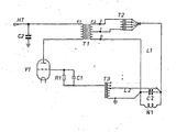
- the tube VI is connected to the aperiodic transformer Tl where the primary winding is represented at El and the secondary winding E2.
- the taps 1 and 2 of this winding are connected to an auxiliary autotransformer T2 intended to carry out a voltage division in order to adapt the generator to its load.
- the energy transport line L1 connects this device to the adaptation box, the composition of which is limited to a battery of capacitors CI associated with the inductor N1. 1
- a second line L2 brings the voltage drawn across the oscillating circuit CI-NI to the excitation autotransformer T3.
- the resistance RI is the gate self-polarization resistance which is associated with the decoupling capacitor Cl; C2 is the decoupling capacitor of the anode voltage.
- Such a device makes it possible to limit the adaptation box to the single capacitor bank; all the adaptation and excitation transformers found in the generator and no longer as previously in the adaptation box.
- the transformer T2 is no longer necessary because it can be provided directly on the secondary of the aperiodic transformer, the number of sockets allowing the desired adaptation.
- the generator is connected to several adaptation boxes, it is possible to provide switching by contactor, as in the known embodiments, but the same excitation transformers T3 and adaptation T2 are used independently of the number of cabinets while in known embodiments each adapter cabinet required an autotransformer and a separate grid transformer.
Landscapes
- Physics & Mathematics (AREA)
- Electromagnetism (AREA)
- Ac-Ac Conversion (AREA)
Applications Claiming Priority (4)
| Application Number | Priority Date | Filing Date | Title |
|---|---|---|---|
| FR8415736A FR2571887A1 (fr) | 1984-10-11 | 1984-10-11 | Perfectionnement au generateur aperiodique |
| FR8415736 | 1984-10-11 | ||
| FR8419859 | 1984-12-24 | ||
| FR8419859A FR2587538B1 (fr) | 1984-12-24 | 1984-12-24 | Perfectionnement au generateur aperiodique |
Publications (1)
| Publication Number | Publication Date |
|---|---|
| EP0248090A1 true EP0248090A1 (de) | 1987-12-09 |
Family
ID=26224200
Family Applications (1)
| Application Number | Title | Priority Date | Filing Date |
|---|---|---|---|
| EP85400465A Withdrawn EP0248090A1 (de) | 1984-10-11 | 1985-03-12 | Aperiodischer Generator |
Country Status (1)
| Country | Link |
|---|---|
| EP (1) | EP0248090A1 (de) |
Cited By (1)
| Publication number | Priority date | Publication date | Assignee | Title |
|---|---|---|---|---|
| AU620482B2 (en) * | 1989-07-14 | 1992-02-20 | Mitsubishi Jukogyo Kabushiki Kaisha | Induction heating apparatus |
Citations (7)
| Publication number | Priority date | Publication date | Assignee | Title |
|---|---|---|---|---|
| FR928971A (fr) * | 1945-06-26 | 1947-12-12 | Rca Corp | Perfectionnements aux appareils transformateurs de courant |
| FR977968A (fr) * | 1942-12-01 | 1951-04-09 | Radio Electr Soc Fr | Appareillage à lampes pour le traitement thermique des métaux par haute fréquence |
| CH287694A (fr) * | 1949-06-22 | 1952-12-15 | Csf | Générateur de courant à haute fréquence, notamment pour chauffage par induction. |
| US2964608A (en) * | 1958-09-30 | 1960-12-13 | William R Maclean | Induction heating thermostable work circuit |
| FR1384779A (fr) * | 1963-11-27 | 1965-01-08 | Applic Electro Thermiques Soc | Générateur à transformateur d'adaptation apériodique |
| US3571644A (en) * | 1969-01-27 | 1971-03-23 | Heurtey Sa | High frequency oscillator for inductive heating |
| FR2216746A1 (de) * | 1973-01-31 | 1974-08-30 | Jakoubovitch Albert |
-
1985
- 1985-03-12 EP EP85400465A patent/EP0248090A1/de not_active Withdrawn
Patent Citations (7)
| Publication number | Priority date | Publication date | Assignee | Title |
|---|---|---|---|---|
| FR977968A (fr) * | 1942-12-01 | 1951-04-09 | Radio Electr Soc Fr | Appareillage à lampes pour le traitement thermique des métaux par haute fréquence |
| FR928971A (fr) * | 1945-06-26 | 1947-12-12 | Rca Corp | Perfectionnements aux appareils transformateurs de courant |
| CH287694A (fr) * | 1949-06-22 | 1952-12-15 | Csf | Générateur de courant à haute fréquence, notamment pour chauffage par induction. |
| US2964608A (en) * | 1958-09-30 | 1960-12-13 | William R Maclean | Induction heating thermostable work circuit |
| FR1384779A (fr) * | 1963-11-27 | 1965-01-08 | Applic Electro Thermiques Soc | Générateur à transformateur d'adaptation apériodique |
| US3571644A (en) * | 1969-01-27 | 1971-03-23 | Heurtey Sa | High frequency oscillator for inductive heating |
| FR2216746A1 (de) * | 1973-01-31 | 1974-08-30 | Jakoubovitch Albert |
Cited By (1)
| Publication number | Priority date | Publication date | Assignee | Title |
|---|---|---|---|---|
| AU620482B2 (en) * | 1989-07-14 | 1992-02-20 | Mitsubishi Jukogyo Kabushiki Kaisha | Induction heating apparatus |
Similar Documents
| Publication | Publication Date | Title |
|---|---|---|
| US2521513A (en) | Stationary induction apparatus | |
| FR2547106A1 (fr) | Dispositif d'equilibrage d'interrupteurs connectes en serie | |
| US3749975A (en) | Adjustable waveform spark source | |
| US3688232A (en) | Capacitive inductive winding | |
| EP0248090A1 (de) | Aperiodischer Generator | |
| GB1484938A (en) | Power factor correcting means | |
| FR2571887A1 (fr) | Perfectionnement au generateur aperiodique | |
| FR2587538A1 (fr) | Perfectionnement au generateur aperiodique | |
| US3849701A (en) | Integrated dual voltage power supply | |
| US2817803A (en) | Direct current voltage step-up device | |
| US1321505A (en) | Rectifier system | |
| HU176291B (en) | Powerful diagnostic x-ray apparatus operated with thyristor current converter | |
| SU1277408A1 (ru) | Устройство передачи информации по проводам линий электропередачи | |
| BE814168A (fr) | Dispositif d'adaptation d'impedance pour generateurs aperiodiques. | |
| DE623655C (de) | ||
| SU29195A1 (ru) | Телефонный аппарат с устранением вли ни исход щего тока на свой телефон | |
| SU714590A1 (ru) | Ферромагнитный преобразователь частоты | |
| SU723546A1 (ru) | Индуктивно-емкостный преобразователь источника напр жени в источник тока | |
| SU603975A2 (ru) | Трехфазный индуктивно-емкостной преобразователь источника напр жени в источник тока | |
| SU813725A1 (ru) | Генератор импульсных напр жений | |
| BE535215A (de) | ||
| US1012524A (en) | Apparatus for automatic regulation of rectifiers and rotary converters. | |
| SU813720A1 (ru) | Устройство дл зар да накопитель-НОгО КОНдЕНСАТОРА | |
| SU806492A1 (ru) | Устройство последовательной компенсацииТ гОВОй СЕТи пЕРЕМЕННОгО ТОКАэлЕКТРичЕСКОй жЕлЕзНОй дОРОги | |
| SU1077729A1 (ru) | Устройство дл питани сварочной дуги переменным током |
Legal Events
| Date | Code | Title | Description |
|---|---|---|---|
| PUAI | Public reference made under article 153(3) epc to a published international application that has entered the european phase |
Free format text: ORIGINAL CODE: 0009012 |
|
| AK | Designated contracting states |
Kind code of ref document: A1 Designated state(s): DE |
|
| 17P | Request for examination filed |
Effective date: 19880505 |
|
| 17Q | First examination report despatched |
Effective date: 19900913 |
|
| STAA | Information on the status of an ep patent application or granted ep patent |
Free format text: STATUS: THE APPLICATION HAS BEEN WITHDRAWN |
|
| 18W | Application withdrawn |
Withdrawal date: 19911227 |