EP0248071B1 - Honing machine - Google Patents
Honing machine Download PDFInfo
- Publication number
- EP0248071B1 EP0248071B1 EP87900208A EP87900208A EP0248071B1 EP 0248071 B1 EP0248071 B1 EP 0248071B1 EP 87900208 A EP87900208 A EP 87900208A EP 87900208 A EP87900208 A EP 87900208A EP 0248071 B1 EP0248071 B1 EP 0248071B1
- Authority
- EP
- European Patent Office
- Prior art keywords
- stroke
- spindle
- speed
- acceleration
- motor
- Prior art date
- Legal status (The legal status is an assumption and is not a legal conclusion. Google has not performed a legal analysis and makes no representation as to the accuracy of the status listed.)
- Expired - Lifetime
Links
Images


Classifications
-
- G—PHYSICS
- G05—CONTROLLING; REGULATING
- G05B—CONTROL OR REGULATING SYSTEMS IN GENERAL; FUNCTIONAL ELEMENTS OF SUCH SYSTEMS; MONITORING OR TESTING ARRANGEMENTS FOR SUCH SYSTEMS OR ELEMENTS
- G05B19/00—Programme-control systems
- G05B19/02—Programme-control systems electric
- G05B19/18—Numerical control [NC], i.e. automatically operating machines, in particular machine tools, e.g. in a manufacturing environment, so as to execute positioning, movement or co-ordinated operations by means of programme data in numerical form
- G05B19/182—Numerical control [NC], i.e. automatically operating machines, in particular machine tools, e.g. in a manufacturing environment, so as to execute positioning, movement or co-ordinated operations by means of programme data in numerical form characterised by the machine tool function, e.g. thread cutting, cam making, tool direction control
-
- G—PHYSICS
- G05—CONTROLLING; REGULATING
- G05B—CONTROL OR REGULATING SYSTEMS IN GENERAL; FUNCTIONAL ELEMENTS OF SUCH SYSTEMS; MONITORING OR TESTING ARRANGEMENTS FOR SUCH SYSTEMS OR ELEMENTS
- G05B19/00—Programme-control systems
- G05B19/02—Programme-control systems electric
- G05B19/18—Numerical control [NC], i.e. automatically operating machines, in particular machine tools, e.g. in a manufacturing environment, so as to execute positioning, movement or co-ordinated operations by means of programme data in numerical form
- G05B19/4093—Numerical control [NC], i.e. automatically operating machines, in particular machine tools, e.g. in a manufacturing environment, so as to execute positioning, movement or co-ordinated operations by means of programme data in numerical form characterised by part programming, e.g. entry of geometrical information as taken from a technical drawing, combining this with machining and material information to obtain control information, named part programme, for the NC machine
- G05B19/40937—Numerical control [NC], i.e. automatically operating machines, in particular machine tools, e.g. in a manufacturing environment, so as to execute positioning, movement or co-ordinated operations by means of programme data in numerical form characterised by part programming, e.g. entry of geometrical information as taken from a technical drawing, combining this with machining and material information to obtain control information, named part programme, for the NC machine concerning programming of machining or material parameters, pocket machining
-
- G—PHYSICS
- G05—CONTROLLING; REGULATING
- G05B—CONTROL OR REGULATING SYSTEMS IN GENERAL; FUNCTIONAL ELEMENTS OF SUCH SYSTEMS; MONITORING OR TESTING ARRANGEMENTS FOR SUCH SYSTEMS OR ELEMENTS
- G05B2219/00—Program-control systems
- G05B2219/30—Nc systems
- G05B2219/37—Measurements
- G05B2219/37405—Contact detection between workpiece and tool, probe, feeler
-
- G—PHYSICS
- G05—CONTROLLING; REGULATING
- G05B—CONTROL OR REGULATING SYSTEMS IN GENERAL; FUNCTIONAL ELEMENTS OF SUCH SYSTEMS; MONITORING OR TESTING ARRANGEMENTS FOR SUCH SYSTEMS OR ELEMENTS
- G05B2219/00—Program-control systems
- G05B2219/30—Nc systems
- G05B2219/43—Speed, acceleration, deceleration control ADC
- G05B2219/43002—Acceleration, deceleration for forward, backward reciprocating movement
-
- G—PHYSICS
- G05—CONTROLLING; REGULATING
- G05B—CONTROL OR REGULATING SYSTEMS IN GENERAL; FUNCTIONAL ELEMENTS OF SUCH SYSTEMS; MONITORING OR TESTING ARRANGEMENTS FOR SUCH SYSTEMS OR ELEMENTS
- G05B2219/00—Program-control systems
- G05B2219/30—Nc systems
- G05B2219/43—Speed, acceleration, deceleration control ADC
- G05B2219/43023—Switch from acceleration to deceleration if mid stroke speed not reached
-
- G—PHYSICS
- G05—CONTROLLING; REGULATING
- G05B—CONTROL OR REGULATING SYSTEMS IN GENERAL; FUNCTIONAL ELEMENTS OF SUCH SYSTEMS; MONITORING OR TESTING ARRANGEMENTS FOR SUCH SYSTEMS OR ELEMENTS
- G05B2219/00—Program-control systems
- G05B2219/30—Nc systems
- G05B2219/43—Speed, acceleration, deceleration control ADC
- G05B2219/43088—Select out of plurality of acceleration profiles
-
- G—PHYSICS
- G05—CONTROLLING; REGULATING
- G05B—CONTROL OR REGULATING SYSTEMS IN GENERAL; FUNCTIONAL ELEMENTS OF SUCH SYSTEMS; MONITORING OR TESTING ARRANGEMENTS FOR SUCH SYSTEMS OR ELEMENTS
- G05B2219/00—Program-control systems
- G05B2219/30—Nc systems
- G05B2219/43—Speed, acceleration, deceleration control ADC
- G05B2219/43097—Table, rom, ram speed table
-
- G—PHYSICS
- G05—CONTROLLING; REGULATING
- G05B—CONTROL OR REGULATING SYSTEMS IN GENERAL; FUNCTIONAL ELEMENTS OF SUCH SYSTEMS; MONITORING OR TESTING ARRANGEMENTS FOR SUCH SYSTEMS OR ELEMENTS
- G05B2219/00—Program-control systems
- G05B2219/30—Nc systems
- G05B2219/43—Speed, acceleration, deceleration control ADC
- G05B2219/43152—Feed in, transfer line, rapid traverse to work, grip speed
-
- G—PHYSICS
- G05—CONTROLLING; REGULATING
- G05B—CONTROL OR REGULATING SYSTEMS IN GENERAL; FUNCTIONAL ELEMENTS OF SUCH SYSTEMS; MONITORING OR TESTING ARRANGEMENTS FOR SUCH SYSTEMS OR ELEMENTS
- G05B2219/00—Program-control systems
- G05B2219/30—Nc systems
- G05B2219/45—Nc applications
- G05B2219/45237—Honing machine
-
- G—PHYSICS
- G05—CONTROLLING; REGULATING
- G05B—CONTROL OR REGULATING SYSTEMS IN GENERAL; FUNCTIONAL ELEMENTS OF SUCH SYSTEMS; MONITORING OR TESTING ARRANGEMENTS FOR SUCH SYSTEMS OR ELEMENTS
- G05B2219/00—Program-control systems
- G05B2219/30—Nc systems
- G05B2219/49—Nc machine tool, till multiple
- G05B2219/49382—Movement reciprocating
-
- G—PHYSICS
- G05—CONTROLLING; REGULATING
- G05B—CONTROL OR REGULATING SYSTEMS IN GENERAL; FUNCTIONAL ELEMENTS OF SUCH SYSTEMS; MONITORING OR TESTING ARRANGEMENTS FOR SUCH SYSTEMS OR ELEMENTS
- G05B2219/00—Program-control systems
- G05B2219/30—Nc systems
- G05B2219/50—Machine tool, machine tool null till machine tool work handling
- G05B2219/50293—Radial setting of tool
-
- Y—GENERAL TAGGING OF NEW TECHNOLOGICAL DEVELOPMENTS; GENERAL TAGGING OF CROSS-SECTIONAL TECHNOLOGIES SPANNING OVER SEVERAL SECTIONS OF THE IPC; TECHNICAL SUBJECTS COVERED BY FORMER USPC CROSS-REFERENCE ART COLLECTIONS [XRACs] AND DIGESTS
- Y02—TECHNOLOGIES OR APPLICATIONS FOR MITIGATION OR ADAPTATION AGAINST CLIMATE CHANGE
- Y02P—CLIMATE CHANGE MITIGATION TECHNOLOGIES IN THE PRODUCTION OR PROCESSING OF GOODS
- Y02P90/00—Enabling technologies with a potential contribution to greenhouse gas [GHG] emissions mitigation
- Y02P90/02—Total factory control, e.g. smart factories, flexible manufacturing systems [FMS] or integrated manufacturing systems [IMS]
Definitions
- the invention relates to a honing machine.
- Honing machines are used for fine-finishing cylindrical bores in work-pieces such as automobile cylinder blocks and hydraulic and pneumatic components of all kinds.
- a honing machine has a rotatable spindle which carries at its end abrasive stones mounted in carriers which may be expanded radially.
- the spindle enters the bore in the work-piece and is rotated as the work-piece and spindle are reciprocated with respect to each other. Radial pressure is applied to urge the stones against the wall of the bore. Forward movement of the spindle causes the stones to trace a helical path in the bore in one sense and reverse movement of the spindle causes the stones to trace a helical path in the opposite sense. Consequently, a cross-hatched honing pattern is made in the bore. For optimum finishing it is found to be important to control the cross-hatch pattern accurately.
- the cross-hatch angle is a function of the stroke velocity in relation to the spindle speed.
- Spindle speed can effectively be maintained constant by controlling a continuously rotating spindle motor of significant inertia.
- the problem of cross-hatch pattern control resolves itself, therefore, to control of stroke velocity.
- the spindle must be repetitively accelerated and decelerated having regard to its position with respect to the work-piece.
- a honing machine comprising a spindle; an expandable honing stone carrier at the end of the spindle; a drive motor for rotating the spindle; a direct-current stroke motor for reciprocating the spindle with respect to a work-piece; a position transducer arrangement for giving a digital output in accordance with the linear stroke position of the spindle with respect to the work-piece; a micro-processor; a memory unit for the micro-processor, which memory unit holds a predetermined position/time profile table; and an input console for manually applying input parameters, the micro-processor being programmed (a) to accept inputs from the console (24) from which can be derived at least the required start and end positions of the stroke and the required mid-stroke speed of the spindle (2), (b) to sample the input from the position transducer arrangement (20) periodically, (c) to compare the actual position of the spindle (2) with the look-up table to derive a positon error signal whereby the stroke motor (67
- This arrangement ensures symmetrical acceleration and deceleration of the spindle even if the required mid-stroke speed is not reached. This is important when the honing machine is to provide for a wide range of bore lengths, since for short bores and for short-stroke local honing the inertia of the system may prevent the required mid-stroke steady speed being met.
- the arrangement described ensures that the acceleration and deceleration modes have priority over the mid-stroke constant velocity mode. It is found that this ensures accuracy in achieving the end points of the bore which is again particularly important for small-piece work.
- a preferred feature of the present invention is to provide a micro-processor program which cycles successively between these six phases and which skips the steady speed phases if necessary.
- a single acceleration curve preferably stored in position/time form can be used for all accelerations and decelerations of a cycle, regardless of stroke length, by reading the curve in the appropriate direction according to the acceleration/deceleration phase concerned.
- symmetry of acceleration/deceleration is ensured and it is not necessary to store a full position/time or velocity/time curve in the computer memory.
- the memory unit may include a family of acceleration position/time profiles, means being provided to select the appropriate one for a particular purpose.
- different profiles may be contained in different plug-in ROM chips which are interchangeable.
- the micro-processor may be programmed to calculate a profile table at the start of a honing operation and to place the table in RAM.
- the velocity during the constant velocity period in the middle of the stroke should have a particular relation to the circumferential velocity of the bore. This depends on the diameter of the bore and the rotational spindle speed. For a given bore diameter the stroke velocity should therefore be adjusted in accordance with spindle speed.
- a cross-hatch angle i.e. angle of stone traverse with respect to the axis of the bore
- the optional angle may be a particular angle between 40° and 65°.
- the micro-processor could therefore be pre-set to achieve any required cross-hatch angle in the middle of the stroke for all bores.
- a required cross-hatch angle input can be made at the console, whereby the microprocessor will modify the correction output to produce a different constant velocity.
- the micro-processor In order to calculate the correction output, the micro-processor requires the rotary spindle speed. This can be derived from a tacho-generator coupled to the spindle motor. Alternatively, spindle speed can be set from the console, and the input to the microprocessor can be derived from the speed setting.
- the micro-processor program may be modified to provide exaggerated local honing within the main honing cycle. For example, it may be desired to effect local honing of the end of a blind bore, either to compensate for under-honing or even to provide a tapered bore.
- This facility may also be effective to correct tapered bores.
- the facility may be provided to specify a short-stroke cycle which has its own restricted end points, presettable, and a given number of strokes. Thus, for example, it may be specified that in each main honing cycle, five short strokes are executed over the innermost 10% of the stroke length.
- the invention is applicable to an arrangement in which the spindle is fixed relative to a bed and the work-piece is reciprocated by the stroke motor.
- the work-piece is fixed and the spindle is reciprocated.
- Drive for the reciprocating spindle could be given through splines from a fixed spindle motor.
- the spindle motor is mounted to be reciprocated with the spindle, the whole assembly being driven by the stroke motor. This has the advantage that the weight of the reciprocating assembly is fixed, regardless of the weight of the work-piece, and spline friction has no effect.
- the acceleration characteristics of the assembly are largely predictable and can be embodied in the position/time profile table without giving rise to significant errors.
- the spindle motor/spindle assembly can be mounted on a sled which can be driven by the stroke motor through a local screw or by means of a chain drive. Naturally, there should be as little back-lash in the system as possible.
- the position transducer arrangement can comprise a linear transducer fixed to the bed of the machine, for example a linear inductosyn or optical grating.
- the transducer arrangement comprises a rotary digital encoder fixed to the spindle of the stroke motor. It is found that this gives a high degree of accuracy, particularly when used in conjunction with a lead screw drive.
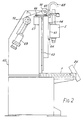
- FIG. 1 there is shown a honing machine for honing a work-piece mounted on a table fixture F.
- a honing spindle 2 carries honing stones at its end which engage the wall of the bore in the work-piece to effect honing.
- the spindle is rotated by a spindle motor (not shown in Figure 1) which is mounted on a carriage which reciprocates vertically on runners under control of a stroke motor mounted in housing H.
- Control of the machine is effected by a micro-processor housed in a housing M.
- a console 24 allows an operator to set various parameters for controlling the machine.
- FIG. 2 shows the structure of the machine in more detail.
- the machine has a frame 60 which supports the table fixture F where work-pieces are clamped.
- the frame provides vertical runners 62 on which is guided a carriage 63 which has rollers 64. Linear bearings may alternatively be used.
- a lead-screw is mounted vertically and has a drive pulley 65 at its upper end. Pulley 65 is coupled by a toothed belt 61 to a pulley 66 on a motor 67.
- the spindle motor is shown at 5 mounted on the carriage and power is conveyed to it by a flexible cable 68.
- a counter-balance arrangement comprises a hydraulic cylinder 69 having a piston which is coupled to the carriage by a chain and pulley arrangement 70, 71, 72. Pressure in the cylinder is controlled to provide a force which precisely counterbalances the weight of the carriage and spindle motor. This arrangement has less inertia than a counter-weight would have.
- the machine of Figures 1 and 2 is a vertical honing machine in which carriage 63 reciprocates vertically, with a counter-balance system as described. However, the principles of the machine apply equally if the carriage is arranged to reciprocate at angles with respect to the vertical, with suitable adjustment of the counterbalance forces. If the carriage reciprocates horizontally, no counterbalancing is required.
- Figure 3 illustrates the principles of the machine in a horizontal arrangement. The work-piece being honed is shown at 1 and is fixed.
- the honing spindle 2 carries the honing stones 3 at its end which engage the wall of the bore 4 in work-piece 1 to effect honing.
- the spindle motor 5 is a 3-phase a.c. motor which comprises a stator 6 and a rotor 7. Rotor 7 has a hollow core which accommodates the hollow spindle 2.
- the carriage 63 which rides on runners 62 and linear reciprocating movement is imparted to the carriage by a lead screw 10 which runs in a nut 9 in the carriage.
- the lead screw is turned by the direct-current stroke motor 67 via toothed belt 61.
- a wedge control system 12 which comprises a direct-current wedge motor 13 which drives a lead screw 14 via a toothed belt and pulley system 15.
- a nut 16 runs on screw 14 and this is coupled to wedge drive strips 17.
- a wedge expansion system which expands the stones 3 outwardly in response to forward axial movement of the strips. The stones are thus urged against the wall of the bore.
- Control of the system is effected by a microprocessor 18.
- the micro-processor receives an input on line 19 from a rotary position encoder 20 fixed to the shaft of the stroke motor 11. This input represents the position of the carriage 63.
- Another input is received on line 21 from a rotary encoder 22 fixed to the lead screw 14. This input represents the radial position of the stones 3.
- a further input is received on line 23 from a drive amplifier (not shown) for the spindle motor. This is a frequency input representative of the speed of the spindle motor.
- Further inputs are applied to the microprocessor from a console 24 which has manually operable push-buttons whereby the operator may set all functions and requirements for the honing operation.
- the micro-processor applies control outputs to a stroke drive unit 25 which drives the stroke motor; a spindle drive unit 26 which drives the spindle motor; and a wedge drive unit 27 which drives the wedge motor.
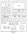
- Figure 4 shows the layout of the console 24.
- the console allows machining and wedge parameters to be put into the micro-processor.
- Two liquid-crystal displays 28 and 29 allow the parameters to be displayed as they are input. The inputs may be recalled at will.
- a machine parameter key-pad 30 has keys for setting the following parameters: hone park (p); start point (q); end point (r); required spindle velocity (s) (mid point); rotary spindle speed (t); stroke length (u); short stroke length (w); and number of short strokes (x).
- the numerical key-pad 31 is used after depression of the appropriate parameter key. Also, there is a test mode facility on key-pad 30.
- a wedge parameter key-pad 32 has keys for setting the following parameters: stone pressure (a); wedge angle (b); stones worn (c); maximum stone pressure (d); retract distance (e); stones in contact (f); approach or initial feed speed (g); and honing, or final feed speed (h).
- a sizing key-pad 33 has keys for setting the following sizing parameters: plug mode; timer mode; timer set; stone wear set; manual compensate; automatic compensate; tolerance; diametric clearance and match gauge.
- a fixture key-pad 34 which relates to control of the work-piece fixture F, has keys for the following functions: manual; step; auto-load; and manual clamp.
- FIG. 5 is a block diagram of the drive circuit for the stroke motor 11.
- the micro-processor is shown at 18 and has associated with it a memory unit 44.
- Unit 44 carries a set of look-up tables LT1, LT2... etc.
- Each table is a table of values relating distance to time as a position/time profile for required acceleration and deceleration of the carriage 63.
- the profiles are constructed from the known characteristics of inertia of the stroke mechanism, frictional resistance and motor torque and in this embodiment are stored permanently in ROM.
- the different tables represent different respective accelerations and the table used for a particular honing operation is selected by means of the acceleration input (v). In the absence of a selected input the table giving the highest acceleration is chosen. In the particular machine described the highest acceleration is 1.2 g. Acceleration is capable of being set in steps of 0.2 g from 0.2 g to 1.2 g. In some embodiments of the invention this upper limit may be higher.
- the micro-processor receives input from the console 24, which defines at least the end of stroke positions required. There are different possible ways of inputting this information. For example, the two stroke end positions may be defined, or one end position and the stroke length or the mid-stroke position and the stroke length, for example. Also derived from console 24 is an input representative of the set spindle speed. An input of position is derived from the position encoder 20 of the stroke motor 11 via a pulse counter PC. This is sampled by the micro-processor regularly, typically every 2 m.Sec. Having regard to the position/time table in memory unit 44 and the inputs applied from console 24, the micro-processor produces a correction output on line 45.
- the correction output is applied to a digital-to-analogue converter 46 which produces a speed input signal to a summing circuit 47.
- the output from circuit 47 is applied to an amplifier 48 to drive the stroke motor 11.
- a pulse rate detector 49 gives an output proportional to the speed of the motor and this is fed back to the summing circuit 47 to be subtracted from the speed input signal from converter 46.
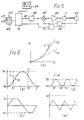
- look-up table LT1 of Figure 5 represented as a graph of position against time.
- this is stored in digital form as a series of positions at spaced intervals of time _ in this embodiment the intervals are 2 msec.
- the control system drives the carriage 63 to follow the acceleration curve C until the input mid-stroke speed is reached. Two speeds are shown at S1 and S2 in Figure 6(a).
- Figure 6(b) shows part of the position/time curve for a control cycle with the mid-stroke velocity set to S1 and the end of the stroke position set to P1, the beginning of the stroke being at P0.
- the carriage follows the acceleration curve C.
- the speed reaches S1 at time t1
- acceleration ceases and the carriage is controlled to proceed at speed S1.
- Deceleration starts at an equal distance from the mid-stroke position that acceleration ceased.
- the curve C is read from the look-up table taking the position as the distance to the end of stroke position.
- speed S1 is reached in the reverse direction
- acceleration in the reverse direction ceases at time t2, and so on.
- Figure 6(c) is a velocity/time curve corresponding to the position/curve of Figure 6(b). It will be seen that the curve of Figure 6(c) is trapezoidal, having flat regions where the carriage speed is constant at S1.
- Figure 6(d) is a position/time curve in which the stroke end position has been set at p2 for a short stroke and the mid-stroke speed has been set at S2.
- the carriage cannot achieve speed S2 before the mid-stroke position.
- the control system operates to over-ride the velocity demand and simultaneously cease acceleration and start deceleration at the mid-stroke position (time t1).
- time t1 time t1
- t2 and t3 there are sudden reversals of acceleration.
- the corresponding velocity/time curve is shown in Figure 6(e). It will be seen that this has a triangular shape and speed S2 is never reached.
- Figure 7 is a diagram showing the flow-chart for the micro-processor program which achieves the characteristics described.
- the cycle of movement has six sub-cycles, SC1 to SC6. These are selected in sequence according to the prevailing time and position of the carriage.
- the demand signals generated are position demands which cause the control circuit to issue velocity control signals to the carriage motor.
- the sub-cycles merge sequentially with one another.
- sub-cycles SC2 and SC5 may be skipped if the set-in steady speed is not achieved.
Abstract
Description
- The invention relates to a honing machine. Honing machines are used for fine-finishing cylindrical bores in work-pieces such as automobile cylinder blocks and hydraulic and pneumatic components of all kinds.
- In general, a honing machine has a rotatable spindle which carries at its end abrasive stones mounted in carriers which may be expanded radially. In a honing operation the spindle enters the bore in the work-piece and is rotated as the work-piece and spindle are reciprocated with respect to each other. Radial pressure is applied to urge the stones against the wall of the bore. Forward movement of the spindle causes the stones to trace a helical path in the bore in one sense and reverse movement of the spindle causes the stones to trace a helical path in the opposite sense. Consequently, a cross-hatched honing pattern is made in the bore. For optimum finishing it is found to be important to control the cross-hatch pattern accurately.
- The cross-hatch angle is a function of the stroke velocity in relation to the spindle speed. Spindle speed can effectively be maintained constant by controlling a continuously rotating spindle motor of significant inertia. The problem of cross-hatch pattern control resolves itself, therefore, to control of stroke velocity. However, because of the reciprocating movement, the spindle must be repetitively accelerated and decelerated having regard to its position with respect to the work-piece.
- In order to control stroke reversal in honing machines it has been the practice to use limit switches or mechanical trips for valves etc., near each end of the stroke. These may be micro-switches, proximity sensors, or the like which, when activated, reverse the drive to the stroke mechanism. The use of limit switches gives an inherently asymmetrical stroke velocity characteristic, and while offering repeatability, does not allow precision control. Often, the reciprocating mechanism is hydraulic. Such a honing machine is described in EP 0046806, for example. While this is a convenient way of driving a system for a large-scale machine with a high power requirement, it again does not lend itself to precision control. The characteristics of the hydraulic system change with temperature, for example. The present invention seeks to provide a honing machine offering very precise control, and while the principles are applicable to large-scale machines, the principal application for the invention is found in small-piece work where precision is particularly important.
- According to the invention there is provided a honing machine comprising a spindle; an expandable honing stone carrier at the end of the spindle; a drive motor for rotating the spindle; a direct-current stroke motor for reciprocating the spindle with respect to a work-piece; a position transducer arrangement for giving a digital output in accordance with the linear stroke position of the spindle with respect to the work-piece; a micro-processor; a memory unit for the micro-processor, which memory unit holds a predetermined position/time profile table; and an input console for manually applying input parameters, the micro-processor being programmed (a) to accept inputs from the console (24) from which can be derived at least the required start and end positions of the stroke and the required mid-stroke speed of the spindle (2), (b) to sample the input from the position transducer arrangement (20) periodically, (c) to compare the actual position of the spindle (2) with the look-up table to derive a positon error signal whereby the stroke motor (67) is driven to correct the error and cause the spindle to follow the position/time profile alternatively in acceleration and deceleration modes, (d) to cause the spindle to continue at the mid-stroke speed between acceleration and deceleration when the mid-stroke speed is reached, and (e) to cause switching at the mid-stroke position from acceleration to deceleration mode if the required mid-stroke speed has not been reached.
- This arrangement ensures symmetrical acceleration and deceleration of the spindle even if the required mid-stroke speed is not reached. This is important when the honing machine is to provide for a wide range of bore lengths, since for short bores and for short-stroke local honing the inertia of the system may prevent the required mid-stroke steady speed being met. The arrangement described ensures that the acceleration and deceleration modes have priority over the mid-stroke constant velocity mode. It is found that this ensures accuracy in achieving the end points of the bore which is again particularly important for small-piece work.
- For example, it may be derived not only to set the stroke length manually but also to allow for automatic re-setting in response to gauging information, to correct perhaps for detected bore tape. Also, it is frequently necessary to include cycles of short-stroke honing within a main honing cycle, particularly for blind bores. With the arrangement in accordance with the invention, a required honing speed can be set and whereas this will apply to limit the speed for long strokes, the requirement will be automatically over-ridden when necessary for shorter strokes. This helps ensure the positional accuracy which is a feature of the preferred positional control system.
- In the reciprocating motion there are six phases: forward acceleration; forward steady speed; forward deceleration; backward acceleration; backward steady speed; and backward deceleration. A preferred feature of the present invention is to provide a micro-processor program which cycles successively between these six phases and which skips the steady speed phases if necessary. Furthermore, a single acceleration curve, preferably stored in position/time form can be used for all accelerations and decelerations of a cycle, regardless of stroke length, by reading the curve in the appropriate direction according to the acceleration/deceleration phase concerned. Thus, symmetry of acceleration/deceleration is ensured and it is not necessary to store a full position/time or velocity/time curve in the computer memory.
- Since the spindle velocity slows at the ends of the stroke and since it is impracticable to change the rotational speed rapidly, the cross-hatch pattern at the ends of the stroke will be different from that in the middle. To achieve an optimum pattern in the middle for as great a length as possible it should be ensured that the velocity during the middle of the stroke is constant at the required value and that acceleration and deceleration are as rapid as possible Maximum acceleration is governed by the torque of the stroke motor, the inertia of the stroke mechanism, and frictional resistance, due largely to the frictional honing force. Generally, therefore, the acceleration profile will be calculated to give substantially the maximum acceleration and deceleration available, having regard to the parameters of the system. However, excessive accelerations and decelerations may cause impact damage, particularly with small work-pieces. A differently shaped profile will then be appropriate. The memory unit may include a family of acceleration position/time profiles, means being provided to select the appropriate one for a particular purpose. Alternatively, different profiles may be contained in different plug-in ROM chips which are interchangeable. In another arrangement, the micro-processor may be programmed to calculate a profile table at the start of a honing operation and to place the table in RAM.
- In order to achieve a required cross-hatch pattern the velocity during the constant velocity period in the middle of the stroke should have a particular relation to the circumferential velocity of the bore. This depends on the diameter of the bore and the rotational spindle speed. For a given bore diameter the stroke velocity should therefore be adjusted in accordance with spindle speed. For many purposes there is a cross-hatch angle (i.e. angle of stone traverse with respect to the axis of the bore) which is optional. Typically, the optional angle may be a particular angle between 40° and 65°. The micro-processor could therefore be pre-set to achieve any required cross-hatch angle in the middle of the stroke for all bores. Alternatively, however, a required cross-hatch angle input can be made at the console, whereby the microprocessor will modify the correction output to produce a different constant velocity.
- In order to calculate the correction output, the micro-processor requires the rotary spindle speed. This can be derived from a tacho-generator coupled to the spindle motor. Alternatively, spindle speed can be set from the console, and the input to the microprocessor can be derived from the speed setting.
- The micro-processor program may be modified to provide exaggerated local honing within the main honing cycle. For example, it may be desired to effect local honing of the end of a blind bore, either to compensate for under-honing or even to provide a tapered bore. This facility may also be effective to correct tapered bores. For this purpose the facility may be provided to specify a short-stroke cycle which has its own restricted end points, presettable, and a given number of strokes. Thus, for example, it may be specified that in each main honing cycle, five short strokes are executed over the innermost 10% of the stroke length.
- The invention is applicable to an arrangement in which the spindle is fixed relative to a bed and the work-piece is reciprocated by the stroke motor. However, it is preferred to provide that the work-piece is fixed and the spindle is reciprocated. Drive for the reciprocating spindle could be given through splines from a fixed spindle motor. However, it is a preferred feature of the invention that the spindle motor is mounted to be reciprocated with the spindle, the whole assembly being driven by the stroke motor. This has the advantage that the weight of the reciprocating assembly is fixed, regardless of the weight of the work-piece, and spline friction has no effect. Thus, the acceleration characteristics of the assembly are largely predictable and can be embodied in the position/time profile table without giving rise to significant errors.
- The spindle motor/spindle assembly can be mounted on a sled which can be driven by the stroke motor through a local screw or by means of a chain drive. Naturally, there should be as little back-lash in the system as possible.
- The position transducer arrangement can comprise a linear transducer fixed to the bed of the machine, for example a linear inductosyn or optical grating. In a preferred embodiment of the invention, however, the transducer arrangement comprises a rotary digital encoder fixed to the spindle of the stroke motor. It is found that this gives a high degree of accuracy, particularly when used in conjunction with a lead screw drive.
- The invention will further be described with reference to the accompanying drawings, of which:
- Figure 1 is a perspective view of a honing machine which embodies the invention;
- Figure 2 is a side elevation of the machine of Figure 1;
- Figure 3 is a schematic diagram illustrating the principles of operation of the machine;
- Figure 4 is a diagram of the control console of the machine;
- Figure 5 is a block diagram of the stroke control circuit of the machine;
- Figure 6 is a set of graphs illustrating the stroke control system of the machine; and
- Figure 7 is a diagram illustrating a program flow-chart of the machine.
- Referring to Figure 1 there is shown a honing machine for honing a work-piece mounted on a table fixture F. A honing
spindle 2 carries honing stones at its end which engage the wall of the bore in the work-piece to effect honing. The spindle is rotated by a spindle motor (not shown in Figure 1) which is mounted on a carriage which reciprocates vertically on runners under control of a stroke motor mounted in housing H. Control of the machine is effected by a micro-processor housed in a housingM. A console 24 allows an operator to set various parameters for controlling the machine. - Figure 2 shows the structure of the machine in more detail. The machine has a
frame 60 which supports the table fixture F where work-pieces are clamped. The frame providesvertical runners 62 on which is guided acarriage 63 which hasrollers 64. Linear bearings may alternatively be used. A lead-screw is mounted vertically and has adrive pulley 65 at its upper end.Pulley 65 is coupled by atoothed belt 61 to apulley 66 on amotor 67. The spindle motor is shown at 5 mounted on the carriage and power is conveyed to it by aflexible cable 68. - A counter-balance arrangement comprises a
hydraulic cylinder 69 having a piston which is coupled to the carriage by a chain andpulley arrangement - The machine of Figures 1 and 2 is a vertical honing machine in which
carriage 63 reciprocates vertically, with a counter-balance system as described. However, the principles of the machine apply equally if the carriage is arranged to reciprocate at angles with respect to the vertical, with suitable adjustment of the counterbalance forces. If the carriage reciprocates horizontally, no counterbalancing is required. Figure 3 illustrates the principles of the machine in a horizontal arrangement. The work-piece being honed is shown at 1 and is fixed. The honingspindle 2 carries the honingstones 3 at its end which engage the wall of thebore 4 in work-piece 1 to effect honing. Thespindle motor 5 is a 3-phase a.c. motor which comprises a stator 6 and a rotor 7. Rotor 7 has a hollow core which accommodates thehollow spindle 2. - The
carriage 63 which rides onrunners 62 and linear reciprocating movement is imparted to the carriage by alead screw 10 which runs in a nut 9 in the carriage. The lead screw is turned by the direct-current stroke motor 67 viatoothed belt 61. - Mounted on stator 6 is a wedge control system 12 which comprises a direct-
current wedge motor 13 which drives alead screw 14 via a toothed belt andpulley system 15. Anut 16 runs onscrew 14 and this is coupled to wedge drive strips 17. At the other end ofstrips 17 is a wedge expansion system which expands thestones 3 outwardly in response to forward axial movement of the strips. The stones are thus urged against the wall of the bore. - The use of a rotor/stator assembly with a hollow rota mounted to reciprocate on the carriage allows the wedge control system to be bolted directly to the stator and the mechanical linkage from the wedge motor to the wedge strips is thus direct without the necessity to by-pass a pulley drive or splined drive system. This enhances the wedge control accuracy.
- Control of the system is effected by a
microprocessor 18. The micro-processor receives an input online 19 from arotary position encoder 20 fixed to the shaft of thestroke motor 11. This input represents the position of thecarriage 63. Another input is received online 21 from arotary encoder 22 fixed to thelead screw 14. This input represents the radial position of thestones 3. A further input is received online 23 from a drive amplifier (not shown) for the spindle motor. This is a frequency input representative of the speed of the spindle motor. Further inputs are applied to the microprocessor from aconsole 24 which has manually operable push-buttons whereby the operator may set all functions and requirements for the honing operation. - The micro-processor applies control outputs to a
stroke drive unit 25 which drives the stroke motor; aspindle drive unit 26 which drives the spindle motor; and awedge drive unit 27 which drives the wedge motor. - Figure 4 shows the layout of the
console 24. The console allows machining and wedge parameters to be put into the micro-processor. Two liquid-crystal displays pad 30 has keys for setting the following parameters: hone park (p); start point (q); end point (r); required spindle velocity (s) (mid point); rotary spindle speed (t); stroke length (u); short stroke length (w); and number of short strokes (x). In order to set a figure for one of the parameters the numerical key-pad 31 is used after depression of the appropriate parameter key. Also, there is a test mode facility on key-pad 30. - A wedge parameter key-
pad 32 has keys for setting the following parameters: stone pressure (a); wedge angle (b); stones worn (c); maximum stone pressure (d); retract distance (e); stones in contact (f); approach or initial feed speed (g); and honing, or final feed speed (h). - A sizing key-
pad 33 has keys for setting the following sizing parameters: plug mode; timer mode; timer set; stone wear set; manual compensate; automatic compensate; tolerance; diametric clearance and match gauge. - A fixture key-
pad 34, which relates to control of the work-piece fixture F, has keys for the following functions: manual; step; auto-load; and manual clamp. - There are manual controls for adjusting the position of the spindle.
Key 35 moves the spindle forwards, key 36 moves it back and "fast" and "inch"keys cycle keys - Figure 5 is a block diagram of the drive circuit for the
stroke motor 11. The micro-processor is shown at 18 and has associated with it amemory unit 44.Unit 44 carries a set of look-up tables LT1, LT2... etc. Each table is a table of values relating distance to time as a position/time profile for required acceleration and deceleration of thecarriage 63. The profiles are constructed from the known characteristics of inertia of the stroke mechanism, frictional resistance and motor torque and in this embodiment are stored permanently in ROM. The different tables represent different respective accelerations and the table used for a particular honing operation is selected by means of the acceleration input (v). In the absence of a selected input the table giving the highest acceleration is chosen. In the particular machine described the highest acceleration is 1.2 g. Acceleration is capable of being set in steps of 0.2 g from 0.2 g to 1.2 g. In some embodiments of the invention this upper limit may be higher. - The micro-processor receives input from the
console 24, which defines at least the end of stroke positions required. There are different possible ways of inputting this information. For example, the two stroke end positions may be defined, or one end position and the stroke length or the mid-stroke position and the stroke length, for example. Also derived fromconsole 24 is an input representative of the set spindle speed. An input of position is derived from theposition encoder 20 of thestroke motor 11 via a pulse counter PC. This is sampled by the micro-processor regularly, typically every 2 m.Sec. Having regard to the position/time table inmemory unit 44 and the inputs applied fromconsole 24, the micro-processor produces a correction output online 45. - The correction output is applied to a digital-to-
analogue converter 46 which produces a speed input signal to a summingcircuit 47. The output fromcircuit 47 is applied to anamplifier 48 to drive thestroke motor 11. Apulse rate detector 49 gives an output proportional to the speed of the motor and this is fed back to the summingcircuit 47 to be subtracted from the speed input signal fromconverter 46. - Referring now to Figure 6 there is shown at (a) look-up table LT1 of Figure 5 represented as a graph of position against time. In the memory unit this is stored in digital form as a series of positions at spaced intervals of time _ in this embodiment the intervals are 2 msec. The table is constructed from the motion equation p = ½ at², where p is position, a is acceleration and t is time. The control system drives the
carriage 63 to follow the acceleration curve C until the input mid-stroke speed is reached. Two speeds are shown at S1 and S2 in Figure 6(a). - Figure 6(b) shows part of the position/time curve for a control cycle with the mid-stroke velocity set to S1 and the end of the stroke position set to P1, the beginning of the stroke being at P0. At the beginning of the stroke the carriage follows the acceleration curve C. When the speed reaches S1 at time t1, acceleration ceases and the carriage is controlled to proceed at speed S1. Deceleration starts at an equal distance from the mid-stroke position that acceleration ceased. To determine deceleration, the curve C is read from the look-up table taking the position as the distance to the end of stroke position. When speed S1 is reached in the reverse direction, acceleration in the reverse direction ceases at time t2, and so on.
- Figure 6(c) is a velocity/time curve corresponding to the position/curve of Figure 6(b). It will be seen that the curve of Figure 6(c) is trapezoidal, having flat regions where the carriage speed is constant at S1.
- Figure 6(d) is a position/time curve in which the stroke end position has been set at p2 for a short stroke and the mid-stroke speed has been set at S2. However, the carriage cannot achieve speed S2 before the mid-stroke position. Under these circumstances the control system operates to over-ride the velocity demand and simultaneously cease acceleration and start deceleration at the mid-stroke position (time t1). Similarly, at times t2 and t3 there are sudden reversals of acceleration. The corresponding velocity/time curve is shown in Figure 6(e). It will be seen that this has a triangular shape and speed S2 is never reached.
- Figure 7 is a diagram showing the flow-chart for the micro-processor program which achieves the characteristics described. The cycle of movement has six sub-cycles, SC1 to SC6. These are selected in sequence according to the prevailing time and position of the carriage. The demand signals generated are position demands which cause the control circuit to issue velocity control signals to the carriage motor. The sub-cycles merge sequentially with one another.
- In the diagram, the current time is t; the current position of the spindle (derived from the encoder) is P; the current look-up table position value is T; the next table position is TN; the start position of the stroke is P0; the end position of the stroke is P1; the mid-point of the stroke is M; the required mid-stroke speed is S; the table-end position (dT/dt = S) is TE; the table start position (dT/dt = 0) is TS; and the demand position applied to the control circuit is D.
- The functions of the respective sub-cycles are:
- SC1 _ forward acceleration
- SC2 _ forward steady speed
- SC3 _ forward deceleration
- SC4 _ backward acceleration
- SC5 _ backward steady speed
- SC6 _ backward deceleration
- It will be seen that sub-cycles SC2 and SC5 may be skipped if the set-in steady speed is not achieved.
Claims (7)
Priority Applications (1)
| Application Number | Priority Date | Filing Date | Title |
|---|---|---|---|
| AT87900208T ATE64221T1 (en) | 1985-12-16 | 1986-12-16 | HONING MACHINE. |
Applications Claiming Priority (5)
| Application Number | Priority Date | Filing Date | Title |
|---|---|---|---|
| GB8530921 | 1985-12-16 | ||
| GB858530921A GB8530921D0 (en) | 1985-12-16 | 1985-12-16 | Honing machine |
| GB868615915A GB8615915D0 (en) | 1986-06-30 | 1986-06-30 | Honing/grinding machine |
| GB8615915 | 1986-06-30 | ||
| PCT/GB1986/000767 WO1987003712A1 (en) | 1985-12-16 | 1986-12-16 | Honing machine |
Publications (2)
| Publication Number | Publication Date |
|---|---|
| EP0248071A1 EP0248071A1 (en) | 1987-12-09 |
| EP0248071B1 true EP0248071B1 (en) | 1991-06-05 |
Family
ID=26290123
Family Applications (2)
| Application Number | Title | Priority Date | Filing Date |
|---|---|---|---|
| EP87900207A Withdrawn EP0248070A1 (en) | 1985-12-16 | 1986-12-16 | Stone expansion control for a honing machine |
| EP87900208A Expired - Lifetime EP0248071B1 (en) | 1985-12-16 | 1986-12-16 | Honing machine |
Family Applications Before (1)
| Application Number | Title | Priority Date | Filing Date |
|---|---|---|---|
| EP87900207A Withdrawn EP0248070A1 (en) | 1985-12-16 | 1986-12-16 | Stone expansion control for a honing machine |
Country Status (3)
| Country | Link |
|---|---|
| US (2) | US4823061A (en) |
| EP (2) | EP0248070A1 (en) |
| WO (2) | WO1987003711A1 (en) |
Families Citing this family (17)
| Publication number | Priority date | Publication date | Assignee | Title |
|---|---|---|---|---|
| JP2696853B2 (en) * | 1987-09-19 | 1998-01-14 | トヨタ自動車株式会社 | Honing equipment |
| US4887221A (en) * | 1987-09-25 | 1989-12-12 | Sunnen Products Company | Computer controlled honing machine using look up table data for automatic programming |
| US5177904A (en) * | 1988-10-15 | 1993-01-12 | Nagel Maschinen-Und Werkzeugfabrik Gmbh | Method for honing workpieces |
| JPH077082Y2 (en) * | 1989-03-10 | 1995-02-22 | ブラザー工業株式会社 | Stroke control device for reciprocating vehicles |
| DE4041869A1 (en) * | 1990-12-27 | 1992-07-02 | Hmr Gmbh | METHOD FOR COMPUTER-CONTROLLED CONTROL OF A MACHINE OR A PROCESS |
| US5426352A (en) * | 1993-09-30 | 1995-06-20 | Caterpillar Inc. | Automatic honing apparatus |
| MXPA06014584A (en) * | 2004-06-22 | 2007-12-04 | Sunnen Products Co | Servo stroking apparatus and system. |
| US8348718B2 (en) * | 2004-06-22 | 2013-01-08 | Sunnen Products Company | Servo stroking method and system for producing special shapes |
| EP1787209B1 (en) * | 2004-09-07 | 2009-04-08 | Sunnen Products Company | Honing feed system having full control of feed force, rate, and position and method of the same |
| US8277280B2 (en) * | 2004-09-07 | 2012-10-02 | Sunnen Products Company | Honing feed system and method employing rapid tool advancement and feed force signal conditioning |
| US20070088454A1 (en) * | 2004-10-25 | 2007-04-19 | Ford Motor Company | System and method for troubleshooting a machine |
| US7383097B2 (en) * | 2004-10-25 | 2008-06-03 | Ford Motor Company | Method for managing machine tool data |
| US7571022B2 (en) * | 2004-10-25 | 2009-08-04 | Ford Motor Company | System and method for monitoring machine health |
| US7409261B2 (en) * | 2004-10-25 | 2008-08-05 | Ford Motor Company | Data management and networking system and method |
| DE102006015359B4 (en) * | 2006-04-03 | 2011-05-19 | Siemens Ag | Operating method for a system with a mechanically movable element and data carrier and control device for implementing such an operating method |
| JP2009095913A (en) * | 2007-10-15 | 2009-05-07 | Nisshin Seisakusho:Kk | Machining tool protection device of machine tool and honing machine |
| US20170239775A1 (en) * | 2016-02-24 | 2017-08-24 | General Electric Company | Systems and methods for honing a shaft |
Family Cites Families (11)
| Publication number | Priority date | Publication date | Assignee | Title |
|---|---|---|---|---|
| US3126672A (en) * | 1964-03-31 | Vertical honing machine | ||
| US3404490A (en) * | 1965-09-17 | 1968-10-08 | Barnes Drill Co | Honing machine with automatic force control |
| US3664217A (en) * | 1969-03-01 | 1972-05-23 | Siemens Ag | Method and system for digital subdivision of the tool feed travel of a numerically controlled machine tool |
| JPS5272077A (en) * | 1975-12-05 | 1977-06-16 | Hitachi Ltd | Positioning system |
| JPS56119365A (en) * | 1980-02-26 | 1981-09-18 | Honda Motor Co Ltd | Composite working device of boring and honing |
| JPS5743205A (en) * | 1980-08-27 | 1982-03-11 | Hitachi Ltd | Speed feedback circuit |
| US4350941A (en) * | 1980-09-19 | 1982-09-21 | Ford Motor Company | Control for automatic machine tool drive |
| DE3039467A1 (en) * | 1980-10-18 | 1982-06-03 | Maschinenfabrik Gehring Gmbh & Co Kg, 7302 Ostfildern | HONING MACHINE FOR MACHINING WORK PIECE BORES, ESPECIALLY BAG HOLES AND METHOD FOR OPERATING THE HONING MACHINE |
| JPS6043261B2 (en) * | 1980-10-30 | 1985-09-27 | ファナック株式会社 | Spindle rotation position control method |
| FR2504047A1 (en) * | 1981-04-16 | 1982-10-22 | Citroen Sa | RODER MACHINE |
| DE3421193A1 (en) * | 1984-06-07 | 1985-12-12 | Maschinenfabrik Gehring Gmbh & Co Kg, 7302 Ostfildern | METHOD FOR ADJUSTING A HONING TOOL AND DEVICE FOR CARRYING OUT THE METHOD |
-
1986
- 1986-12-16 WO PCT/GB1986/000766 patent/WO1987003711A1/en not_active Application Discontinuation
- 1986-12-16 WO PCT/GB1986/000767 patent/WO1987003712A1/en active IP Right Grant
- 1986-12-16 EP EP87900207A patent/EP0248070A1/en not_active Withdrawn
- 1986-12-16 US US07/091,574 patent/US4823061A/en not_active Expired - Fee Related
- 1986-12-16 EP EP87900208A patent/EP0248071B1/en not_active Expired - Lifetime
- 1986-12-16 US US07/091,572 patent/US4816731A/en not_active Expired - Fee Related
Also Published As
| Publication number | Publication date |
|---|---|
| US4823061A (en) | 1989-04-18 |
| EP0248071A1 (en) | 1987-12-09 |
| EP0248070A1 (en) | 1987-12-09 |
| US4816731A (en) | 1989-03-28 |
| WO1987003711A1 (en) | 1987-06-18 |
| WO1987003712A1 (en) | 1987-06-18 |
Similar Documents
| Publication | Publication Date | Title |
|---|---|---|
| EP0248071B1 (en) | Honing machine | |
| CA2035020C (en) | Injection molding machines having a brushless dc drive system | |
| US4956945A (en) | Internal grinder | |
| US4573379A (en) | Apparatus for producing an adjusting torque | |
| US6064028A (en) | Resistance forge welding machine | |
| US4353018A (en) | Control system for synchronized operation of machine tool motors | |
| JPS61288952A (en) | Method and device for manufacturing cutting chip on rotary machining of work | |
| EP0553849A1 (en) | Device for clamping a workpiece | |
| US4350941A (en) | Control for automatic machine tool drive | |
| JP2708056B2 (en) | Machine tools for processing workpieces | |
| EP0232305B1 (en) | Machine tool control systems | |
| US4368412A (en) | Microprocessor-controlled motor drive control system | |
| EP0431818B1 (en) | Apparatus for detecting machining conditions in a machine tool | |
| US4375670A (en) | Machine tool for machining crankshafts and control system for the machine tool | |
| GB2061554A (en) | Control System for Producing Crankshafts | |
| US3949286A (en) | Digital position control | |
| JP2694508B2 (en) | Method for intermittently straightening wire | |
| US4499690A (en) | Split stations surface grinding apparatus | |
| EP0081383A2 (en) | Improvements relating to honing | |
| US4150513A (en) | Method for grinding | |
| EP0034033B1 (en) | Electric motor drive control system | |
| JPH09155688A (en) | Work movement control device | |
| EP0135620A1 (en) | Horizontal honing machine | |
| JPH0523969A (en) | Stop position setting method and device in turning tool | |
| RU2031771C1 (en) | System to control drives of an automatic to grind spiral grooves of cutting tool |
Legal Events
| Date | Code | Title | Description |
|---|---|---|---|
| PUAI | Public reference made under article 153(3) epc to a published international application that has entered the european phase |
Free format text: ORIGINAL CODE: 0009012 |
|
| 17P | Request for examination filed |
Effective date: 19870718 |
|
| AK | Designated contracting states |
Kind code of ref document: A1 Designated state(s): AT BE CH DE FR GB IT LI LU NL SE |
|
| 17Q | First examination report despatched |
Effective date: 19881230 |
|
| GRAA | (expected) grant |
Free format text: ORIGINAL CODE: 0009210 |
|
| AK | Designated contracting states |
Kind code of ref document: B1 Designated state(s): AT BE CH DE FR GB IT LI LU NL SE |
|
| PG25 | Lapsed in a contracting state [announced via postgrant information from national office to epo] |
Ref country code: IT Free format text: LAPSE BECAUSE OF FAILURE TO SUBMIT A TRANSLATION OF THE DESCRIPTION OR TO PAY THE FEE WITHIN THE PRE;WARNING: LAPSES OF ITALIAN PATENTS WITH EFFECTIVE DATE BEFORE 2007 MAY HAVE OCCURRED AT ANY TIME BEFORE 2007. THE CORRECT EFFECTIVE DATE MAY BE DIFFERENT FROM THE ONE RECORDED.SCRIBED TIME-LIMIT Effective date: 19910605 Ref country code: CH Effective date: 19910605 Ref country code: SE Effective date: 19910605 Ref country code: BE Effective date: 19910605 Ref country code: NL Effective date: 19910605 Ref country code: AT Effective date: 19910605 Ref country code: LI Effective date: 19910605 |
|
| REF | Corresponds to: |
Ref document number: 64221 Country of ref document: AT Date of ref document: 19910615 Kind code of ref document: T |
|
| REF | Corresponds to: |
Ref document number: 3679670 Country of ref document: DE Date of ref document: 19910711 |
|
| REG | Reference to a national code |
Ref country code: CH Ref legal event code: PL |
|
| EN | Fr: translation not filed | ||
| PG25 | Lapsed in a contracting state [announced via postgrant information from national office to epo] |
Ref country code: FR Effective date: 19911025 |
|
| NLV1 | Nl: lapsed or annulled due to failure to fulfill the requirements of art. 29p and 29m of the patents act | ||
| PG25 | Lapsed in a contracting state [announced via postgrant information from national office to epo] |
Ref country code: GB Effective date: 19911216 |
|
| PG25 | Lapsed in a contracting state [announced via postgrant information from national office to epo] |
Ref country code: LU Free format text: LAPSE BECAUSE OF NON-PAYMENT OF DUE FEES Effective date: 19911231 |
|
| PLBE | No opposition filed within time limit |
Free format text: ORIGINAL CODE: 0009261 |
|
| STAA | Information on the status of an ep patent application or granted ep patent |
Free format text: STATUS: NO OPPOSITION FILED WITHIN TIME LIMIT |
|
| 26N | No opposition filed | ||
| GBPC | Gb: european patent ceased through non-payment of renewal fee | ||
| PG25 | Lapsed in a contracting state [announced via postgrant information from national office to epo] |
Ref country code: DE Effective date: 19920901 |
|
| REG | Reference to a national code |
Ref country code: FR Ref legal event code: ST |