EP0247947A1 - Einbahnpumpvorrichtung mit Umkehrpumpe - Google Patents
Einbahnpumpvorrichtung mit Umkehrpumpe Download PDFInfo
- Publication number
- EP0247947A1 EP0247947A1 EP87401205A EP87401205A EP0247947A1 EP 0247947 A1 EP0247947 A1 EP 0247947A1 EP 87401205 A EP87401205 A EP 87401205A EP 87401205 A EP87401205 A EP 87401205A EP 0247947 A1 EP0247947 A1 EP 0247947A1
- Authority
- EP
- European Patent Office
- Prior art keywords
- bore
- outlet
- inlet
- intermediate chambers
- pump
- Prior art date
- Legal status (The legal status is an assumption and is not a legal conclusion. Google has not performed a legal analysis and makes no representation as to the accuracy of the status listed.)
- Granted
Links
- 238000005086 pumping Methods 0.000 title claims abstract description 22
- 230000002441 reversible effect Effects 0.000 title claims abstract description 10
- 239000012530 fluid Substances 0.000 claims abstract description 31
- 125000006850 spacer group Chemical group 0.000 claims abstract description 10
- 238000009826 distribution Methods 0.000 claims description 8
- 238000005461 lubrication Methods 0.000 claims description 6
- 230000000994 depressogenic effect Effects 0.000 claims description 5
- 238000004519 manufacturing process Methods 0.000 claims description 2
- 239000003921 oil Substances 0.000 description 18
- 206010061876 Obstruction Diseases 0.000 description 2
- 239000012535 impurity Substances 0.000 description 2
- 238000003475 lamination Methods 0.000 description 2
- 239000010687 lubricating oil Substances 0.000 description 2
- 230000006866 deterioration Effects 0.000 description 1
- 230000010354 integration Effects 0.000 description 1
- 239000007788 liquid Substances 0.000 description 1
- 230000014759 maintenance of location Effects 0.000 description 1
- 230000000877 morphologic effect Effects 0.000 description 1
- 230000002093 peripheral effect Effects 0.000 description 1
- 239000003507 refrigerant Substances 0.000 description 1
- 230000001105 regulatory effect Effects 0.000 description 1
Images


Classifications
-
- F—MECHANICAL ENGINEERING; LIGHTING; HEATING; WEAPONS; BLASTING
- F04—POSITIVE - DISPLACEMENT MACHINES FOR LIQUIDS; PUMPS FOR LIQUIDS OR ELASTIC FLUIDS
- F04C—ROTARY-PISTON, OR OSCILLATING-PISTON, POSITIVE-DISPLACEMENT MACHINES FOR LIQUIDS; ROTARY-PISTON, OR OSCILLATING-PISTON, POSITIVE-DISPLACEMENT PUMPS
- F04C14/00—Control of, monitoring of, or safety arrangements for, machines, pumps or pumping installations
- F04C14/04—Control of, monitoring of, or safety arrangements for, machines, pumps or pumping installations specially adapted for reversible machines or pumps
Definitions
- the invention relates to pumping, that is to say the circulation and / or pressure of a fluid, in particular a liquid.
- pumping has a meaning which is defined by the fact that the fluid is sucked from one side and discharged from the other.
- It relates more precisely to a device whose active member is a rotary pump and which makes it possible to avoid reversing in the direction of pumping when the direction of rotation of the pump is reversed.
- a fluid circuit (oil for example) comprises a pumping device to ensure a certain flow rate through a member (bearings of rotating machines for example) which must be traversed by this fluid.
- the circuit further comprises an oil tank, a filter, a pressure regulator and a heat exchanger (refrigerant).
- a first known device is used for this purpose. It is shown in principle in Figure 1.
- the pump is functionally associated with four valves.
- a screw pump 100 can push the lubricating oil of the bearings of a rotary machine in two opposite directions, that is to say either from a first intermediate chamber 102 to a second intermediate chamber 104, or in the opposite direction.
- An inlet chamber 106 provided with an inlet opening communicates with each of these two intermediate chambers 102 or 104 by a valve 108 or 110 allowing the oil to pass from this inlet chamber to this intermediate chamber but not In the opposite way.
- a chamber and an outlet opening 112 communicate with each of these two intermediate chambers, 102 or 104, by a valve 114 or 116 allowing the oil to pass from this intermediate chamber to this outlet chamber but not in the direction reverse.
- the case shown is that where the pump 100 pushes the oil towards the chamber 104 according to the arrow 118.
- the valves 110 and 114 are open and the valves 108 and 116 closed by the oil pressure created by the pump 100. The oil is then sucked into the inlet chamber 106 into which it penetrates according to arrow 120, and discharged into the outlet chamber 112 from which it leaves according to arrow 122.
- valves 110 and 114 close, the valves 108 and 116 open and the oil enters and leaves again according to the arrows 120 and 122.
- This device makes it possible to pump large flow rates but has the drawback of using valves which are either easily subject to deterioration, or bulky, or expensive.
- a second known unidirectional pumping device is described in the document patent SU-A 180093 and avoids the use such valves.
- It comprises - first and second intermediate chambers, a rotary pump connected between these two intermediate chambers to push the fluid to be pumped from one of these intermediate chambers which then becomes depressed towards the other which is then compressed, the direction of this thrust changing with the direction of rotation of this pump , and this pump being driven by said motor so that the direction of this thrust is also capable of reversing and that each of these two first and second intermediate chambers can be sometimes depressed, sometimes compressed, - and unidirectional inlet communication means to allow the fluid to be pumped to pass from said inlet opening to each of these two intermediate chambers, and outlet to allow this fluid to pass from each of these two intermediate chambers to said outlet opening, these means being passive means driven by the pressure difference appearing in this fluid between the two intermediate chambers under the action of said pump, so that this pump always pushes this fluid from the opening of entry towards the exit opening whatever the direction of its rotation.
- This second known device is distinguished from the first by the following arrangements which are common to this second device and to the device according to the invention: - Said unidirectional inlet communication means comprise an inlet bore extending from a first to a second end which communicate with said first and second intermediate chambers, respectively, said inlet opening communicating with this bore through an opening median of the side wall thereof.
- - stop means, - and an inlet distributor drawer sliding in this bore inlet, under the pressure of said pressure difference between intermediate chambers, between a first and second extreme positions defined by said stops and located on the side of said first and second ends of this bore, respectively, - Said unidirectional outlet communication means comprising an outlet bore extending between a first and a second end which communicate with said first and second intermediate chambers, respectively, a median opening of the side wall of this bore communicating with said opening of exit, - stop means, - And an outlet distributor drawer closing this outlet bore and sliding therein, under the pressure of said pressure difference between intermediate chambers, between a first and a second extreme positions defined by said stops on the side of this first and of this second ends, respectively.
- the object of the present invention is to produce in a simple and economical manner a unidirectional pumping device with a reversible pump capable of pumping higher flow rates without having the drawbacks of valve devices.
- the device according to the invention has the common arrangements previously indicated.
- said inlet drawer comprising first and second shutter heads each suitable for closing a section of this bore on the side of said first and said second lateral recesses, respectively, - And a spacer connecting these two heads and keeping them at a distance from each other, the length of this spacer and the positions of said stops being such that the first or second head closes said bore between said first or second lateral recess and said median opening and that the second or first head is beyond said second or first lateral recess when the drawer is in its said second or first extreme position, respectively, - Said first and second extreme positions of the outlet drawer placing this drawer between on the one hand said median opening of the outlet bore and on the other hand said first and second ends of this bore, so that this drawer, when it is in these positions
- the two said inlet and outlet bores extend parallel, in a common longitudinal direction, from a first to a second face of a pumping body, said pump being arranged in a pump dug in this same body and extending from this first to this second face, said first or second intermediate chamber being formed between this first or second face and a first or second plate extending opposite this face at a distance from that here, these plates cooperating with means formed by said drawers at their two ends to constitute said stop means, - And said lateral recesses and median openings being formed in said body.
- Such an arrangement facilitates the production of an integrated pumping device.
- the pumping device consists of a distribution box which must be connected to an external reversible pump, the type of which may be any, this box comprising said inlet and outlet openings, - said first and second intermediate chamber, - a first and a second connection openings for connecting said pump to this first and to this second chamber, respectively, - And said one-way communication means.
- the two said inlet and outlet bores extend parallel, in a common longitudinal direction, from a first to a second face of a distribution body, said first or second intermediate chamber being constituted between this first or second face and a first or second plate extending opposite this face at a distance from the latter, these plates cooperating with means formed by said drawers at their two ends to constitute said abutment means, - And said lateral recesses and median openings being formed in said body.
- the pumping device of this first embodiment of the invention comprises a pump of the "screw" type with three rotors.
- the juxtaposed rotors of the pump P are represented by their axes which project on the same line 1, axis of the central rotor, and they can be distinguished in 1a, 1, 1b in FIG. 4. and on the other side of the axis are dug two parallel inlet and outlet bores marked respectively 4 and 5.
- the previously mentioned inlet drawer 6 has a longitudinal recess in its part median which constitutes a spacer 62 between two heads marked 61 and 63.
- the outlet drawer 7, shorter, is not hollowed out: these different morphological characteristics of the two drawers are justified by the description below of the operation and additional provisions of the pumping device.
- the drawers are dimensioned so that, in this configuration, the edge of the median recess 13 is released by the face 73 of the drawer 7, while the median recess 14 is released by the edge 63 ⁇ of the recess around the spacer 62 of drawer 6 and that edge 61 ⁇ releases a communication which is seen at the end in fig.4. It follows from this configuration that the oil flows from the recess 14 which constitutes the inlet chamber to the recess 13 which constitutes the outlet chamber, through the bore 4 around the spacer 62, the recess 9, chamber 8, pump P, chamber 8 ⁇ and bore 5.
- the pump When the pump turns in the direction such that the fluid circulates in the direction 204 of fig.3, it is the chamber 8 ⁇ which is depressed and the chamber 8 compressed.
- the relative overpressure in the chamber 8 pushes the drawers 6 and 7 into abutment at 68 ⁇ and 78 ⁇ ; in this configuration, the edge 63 ⁇ releases a communication between the bore 4 and the chamber 8 ⁇ through the recess 9 ⁇ .
- the edge 71 of the drawer 7 releases the recess 13. It generally results from this that the oil circulates from 14 to 13 through the bore 4 around the spacer 62, the recess 9 ⁇ , the chamber 8 ⁇ , pump P, chamber 8 and bore 5.
- the advantages of the device according to the invention which has just been described are functional and easy to produce: -
- the path of the fluid is simpler: it practically sees only one lamination and one chamber (Fig.2) instead of two lamination and two chambers in the device known in Fig.1.
- - The risk of damage to the valve seats is eliminated.
- - The risks of wear of the guides and vibration of the valves are also eliminated thanks to the quality of the guidance of the drawers by the bores.
- the integration of the assembly constituted by the pump, the bores and the dispenser drawers according to the invention can be carried out in relatively very good conditions because the main functional elements are constituted by cylindrical bores and cylinders with parallel axes.
- the device which has just been described according to the invention allows a higher flow rate. It is less affected by the risk of obstruction. It does not require the use of springs.
- peripheral recesses of the drawers and the lateral recesses of the walls of the bores are less costly to produce than internal channels and less sensitive to the impurities which the pumped fluid can contain.
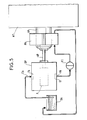
- FIG. 5 represents a lubrication circuit comprising the device described above: a rotary machine MT such as a high power alternator is mounted on an AR shaft which is supported by two bearings such as PA. It is the lubrication circuit of these bearings which comprises this DP pumping device. The latter's pump P is driven by a pump shaft AP extending the shaft AR of the machine.
- This circuit comprises a tank, that is to say the tank previously mentioned BA in which the oil is withdrawn by a suction pipe TA connected to the inlet chamber 14.
- the oil is discharged into a discharge pipe TR connected to the outlet chamber 13, and it is introduced under pressure into the bearings such as PA after having passed through a filter FI.
- the distribution box shown in FIGS. 6 to 8 constitutes a second embodiment of the invention when it is connected to a reversible pump (not shown) by two connection openings represented in the form of two pipes 380 and 382. Apart from these openings and the absence of this pump, this box is similar to the device described above, the homologous elements bearing in this box, the same reference numbers increased by 300.
- the inlet and outlet distributor drawers carry example numbers 306 and 307, respectively.
- the two said inlet and outlet bores 304, 305 extend parallel, in a common longitudinal direction 301, from a first 303A to a second 303B facing a distribution body 303.
- Said first 308 or second 308 ⁇ chamber intermediate is formed between this first or second face and a first 384 or second 384 ⁇ plate extending opposite this face at a distance from the latter. These plates cooperate with means 368, 378 formed by said drawers 306, 307 at their two ends to constitute said stop means.
- Said lateral recesses 309, 309 ⁇ and median openings 314, 313 are formed in said body.
Landscapes
- Engineering & Computer Science (AREA)
- Mechanical Engineering (AREA)
- General Engineering & Computer Science (AREA)
- Electromagnetic Pumps, Or The Like (AREA)
- Structures Of Non-Positive Displacement Pumps (AREA)
- Rotary Pumps (AREA)
- Details And Applications Of Rotary Liquid Pumps (AREA)
- Lubrication Of Internal Combustion Engines (AREA)
- Hydraulic Motors (AREA)
Priority Applications (1)
| Application Number | Priority Date | Filing Date | Title |
|---|---|---|---|
| AT87401205T ATE48026T1 (de) | 1986-05-29 | 1987-05-27 | Einbahnpumpvorrichtung mit umkehrpumpe. |
Applications Claiming Priority (2)
| Application Number | Priority Date | Filing Date | Title |
|---|---|---|---|
| FR8607725A FR2599435B1 (fr) | 1986-05-29 | 1986-05-29 | Dispositif de pompage unidirectionnel a pompe reversible. |
| FR8607725 | 1986-05-29 |
Publications (2)
| Publication Number | Publication Date |
|---|---|
| EP0247947A1 true EP0247947A1 (de) | 1987-12-02 |
| EP0247947B1 EP0247947B1 (de) | 1989-11-15 |
Family
ID=9335788
Family Applications (1)
| Application Number | Title | Priority Date | Filing Date |
|---|---|---|---|
| EP87401205A Expired EP0247947B1 (de) | 1986-05-29 | 1987-05-27 | Einbahnpumpvorrichtung mit Umkehrpumpe |
Country Status (6)
| Country | Link |
|---|---|
| EP (1) | EP0247947B1 (de) |
| AT (1) | ATE48026T1 (de) |
| DE (1) | DE3761002D1 (de) |
| ES (1) | ES2012092B3 (de) |
| FR (1) | FR2599435B1 (de) |
| GR (1) | GR3000345T3 (de) |
Citations (4)
| Publication number | Priority date | Publication date | Assignee | Title |
|---|---|---|---|---|
| US2865301A (en) * | 1953-06-24 | 1958-12-23 | Auto Research Corp | Lubrication |
| CH346738A (de) * | 1956-05-03 | 1960-05-31 | Oerlikon Maschf | Fördereinrichtung mit einer Pumpe, die in beiden Drehrichtungen arbeitet |
| GB936679A (en) * | 1960-04-22 | 1963-09-11 | Pneumatikus Es Hidraulikus Gep | Improvements in or relating to screw pumps |
| US3120190A (en) * | 1961-03-02 | 1964-02-04 | Falk Corp | Gear pump |
-
1986
- 1986-05-29 FR FR8607725A patent/FR2599435B1/fr not_active Expired
-
1987
- 1987-05-27 AT AT87401205T patent/ATE48026T1/de not_active IP Right Cessation
- 1987-05-27 DE DE8787401205T patent/DE3761002D1/de not_active Expired
- 1987-05-27 ES ES87401205T patent/ES2012092B3/es not_active Expired - Lifetime
- 1987-05-27 EP EP87401205A patent/EP0247947B1/de not_active Expired
-
1990
- 1990-02-07 GR GR90400071T patent/GR3000345T3/el unknown
Patent Citations (4)
| Publication number | Priority date | Publication date | Assignee | Title |
|---|---|---|---|---|
| US2865301A (en) * | 1953-06-24 | 1958-12-23 | Auto Research Corp | Lubrication |
| CH346738A (de) * | 1956-05-03 | 1960-05-31 | Oerlikon Maschf | Fördereinrichtung mit einer Pumpe, die in beiden Drehrichtungen arbeitet |
| GB936679A (en) * | 1960-04-22 | 1963-09-11 | Pneumatikus Es Hidraulikus Gep | Improvements in or relating to screw pumps |
| US3120190A (en) * | 1961-03-02 | 1964-02-04 | Falk Corp | Gear pump |
Also Published As
| Publication number | Publication date |
|---|---|
| ATE48026T1 (de) | 1989-12-15 |
| GR3000345T3 (en) | 1991-06-07 |
| DE3761002D1 (en) | 1989-12-21 |
| FR2599435B1 (fr) | 1988-08-05 |
| EP0247947B1 (de) | 1989-11-15 |
| ES2012092B3 (es) | 1990-03-01 |
| FR2599435A1 (fr) | 1987-12-04 |
Similar Documents
| Publication | Publication Date | Title |
|---|---|---|
| EP3189998B1 (de) | Hydraulische vorrichtung, die einen niedrigdruck-wahlschalter umfasst und fahrzeug, das eine solche vorrichtung umfasst | |
| EP0108665B1 (de) | Fluidumfilter | |
| FR2541387A1 (fr) | Machine hydraulique ou pneumatique notamment formant pompe ou moteur | |
| EP0558389A1 (de) | Hydraulische Kolbenpumpe mit Einlassventilen | |
| FR1464360A (fr) | Pompe à débit variable | |
| FR2546981A1 (fr) | Machine hydraulique comprenant deux pompes ou moteurs a engrenages | |
| FR2706538A1 (fr) | Mécanisme à fluide sous pression tel qu'un moteur ou une pompe, réversible, à au moins deux cylindrées de fonctionnement. | |
| EP0247947B1 (de) | Einbahnpumpvorrichtung mit Umkehrpumpe | |
| EP0736691B1 (de) | Innenzahnradpumpe mit radialen Zuführungsröhren | |
| EP3163076B1 (de) | Hydraulische maschine mit zwei schluckvolumina und einem sicherheitsventil | |
| FR2464391A1 (fr) | Amplificateur de couple hydraulique, notamment pour des dispositifs de direction | |
| FR2536475A1 (fr) | Dispositif hydrostatique de commande, notamment de direction | |
| EP0365420B1 (de) | Druckflüssigkeitsmechanismus mit zwei Hubvolumen und seine Anwendung in einem geschlossenen Kreis | |
| FR2641335A1 (fr) | Pompe d'injection de carburant a commande electrique, a plusieurs pistons ou le piston rotatif est lui-meme utilise comme vanne de commande d'alimentation de carburant | |
| EP0428192A2 (de) | Stufenloses hydrostatisches Radialkolbengetriebe | |
| FR2747743A1 (fr) | Pompe a engrenages | |
| FR2536474A1 (fr) | Dispositif de commande hydrostatique, notamment de direction | |
| EP0526333A1 (de) | Druckflüssigkeitsvorrichtung mit Ausgleichsräumen | |
| FR2766242A1 (fr) | Pompe a engrenages | |
| EP2865892A1 (de) | Hydraulikkolbenpumpe mit Verteilung durch Zwei-Wege-Scheibe | |
| EP0067918B1 (de) | Hydrostatischer Motor mit axial gleitenden Schiebern | |
| FR2582738A1 (fr) | Machine hydraulique a pistons axiaux a distributeur central et flottant pouvant fonctionner soit en moteur, soit en pompe | |
| FR2465099A1 (fr) | Servomoteur forme d'une servovalve commandant un moteur hydraulique a barillet | |
| FR2516603A1 (fr) | Moteur a palettes a plusieurs cylindrees muni d'un dispositif d'etancheite compense | |
| FR2645599A1 (fr) | Pompe a vide, seche, a palettes |
Legal Events
| Date | Code | Title | Description |
|---|---|---|---|
| PUAI | Public reference made under article 153(3) epc to a published international application that has entered the european phase |
Free format text: ORIGINAL CODE: 0009012 |
|
| AK | Designated contracting states |
Kind code of ref document: A1 Designated state(s): AT BE CH DE ES FR GB GR IT LI LU NL SE |
|
| 17P | Request for examination filed |
Effective date: 19880531 |
|
| 17Q | First examination report despatched |
Effective date: 19890313 |
|
| GRAA | (expected) grant |
Free format text: ORIGINAL CODE: 0009210 |
|
| AK | Designated contracting states |
Kind code of ref document: B1 Designated state(s): AT BE CH DE ES FR GB GR IT LI LU NL SE |
|
| REF | Corresponds to: |
Ref document number: 48026 Country of ref document: AT Date of ref document: 19891215 Kind code of ref document: T |
|
| GBT | Gb: translation of ep patent filed (gb section 77(6)(a)/1977) | ||
| REF | Corresponds to: |
Ref document number: 3761002 Country of ref document: DE Date of ref document: 19891221 |
|
| ITF | It: translation for a ep patent filed | ||
| REG | Reference to a national code |
Ref country code: GR Ref legal event code: FG4A Free format text: 3000345 |
|
| PLBE | No opposition filed within time limit |
Free format text: ORIGINAL CODE: 0009261 |
|
| STAA | Information on the status of an ep patent application or granted ep patent |
Free format text: STATUS: NO OPPOSITION FILED WITHIN TIME LIMIT |
|
| 26N | No opposition filed | ||
| PGFP | Annual fee paid to national office [announced via postgrant information from national office to epo] |
Ref country code: GB Payment date: 19910424 Year of fee payment: 5 |
|
| PGFP | Annual fee paid to national office [announced via postgrant information from national office to epo] |
Ref country code: GR Payment date: 19910425 Year of fee payment: 5 |
|
| PGFP | Annual fee paid to national office [announced via postgrant information from national office to epo] |
Ref country code: ES Payment date: 19910514 Year of fee payment: 5 |
|
| PGFP | Annual fee paid to national office [announced via postgrant information from national office to epo] |
Ref country code: AT Payment date: 19910515 Year of fee payment: 5 |
|
| PGFP | Annual fee paid to national office [announced via postgrant information from national office to epo] |
Ref country code: SE Payment date: 19910521 Year of fee payment: 5 |
|
| PGFP | Annual fee paid to national office [announced via postgrant information from national office to epo] |
Ref country code: CH Payment date: 19910523 Year of fee payment: 5 |
|
| PGFP | Annual fee paid to national office [announced via postgrant information from national office to epo] |
Ref country code: FR Payment date: 19910530 Year of fee payment: 5 |
|
| ITTA | It: last paid annual fee | ||
| PGFP | Annual fee paid to national office [announced via postgrant information from national office to epo] |
Ref country code: NL Payment date: 19910531 Year of fee payment: 5 |
|
| PGFP | Annual fee paid to national office [announced via postgrant information from national office to epo] |
Ref country code: BE Payment date: 19910605 Year of fee payment: 5 |
|
| PGFP | Annual fee paid to national office [announced via postgrant information from national office to epo] |
Ref country code: LU Payment date: 19910607 Year of fee payment: 5 |
|
| PGFP | Annual fee paid to national office [announced via postgrant information from national office to epo] |
Ref country code: DE Payment date: 19910612 Year of fee payment: 5 |
|
| EPTA | Lu: last paid annual fee | ||
| PG25 | Lapsed in a contracting state [announced via postgrant information from national office to epo] |
Ref country code: LU Free format text: LAPSE BECAUSE OF NON-PAYMENT OF DUE FEES Effective date: 19920527 Ref country code: GB Effective date: 19920527 Ref country code: AT Effective date: 19920527 |
|
| PG25 | Lapsed in a contracting state [announced via postgrant information from national office to epo] |
Ref country code: SE Effective date: 19920528 Ref country code: ES Free format text: LAPSE BECAUSE OF NON-PAYMENT OF DUE FEES Effective date: 19920528 |
|
| PG25 | Lapsed in a contracting state [announced via postgrant information from national office to epo] |
Ref country code: LI Effective date: 19920531 Ref country code: CH Effective date: 19920531 Ref country code: BE Effective date: 19920531 |
|
| BERE | Be: lapsed |
Owner name: ALSTHOM Effective date: 19920531 |
|
| PG25 | Lapsed in a contracting state [announced via postgrant information from national office to epo] |
Ref country code: GR Free format text: THE PATENT HAS BEEN ANNULLED BY A DECISION OF A NATIONAL AUTHORITY Effective date: 19921130 |
|
| PG25 | Lapsed in a contracting state [announced via postgrant information from national office to epo] |
Ref country code: NL Effective date: 19921201 |
|
| NLV4 | Nl: lapsed or anulled due to non-payment of the annual fee | ||
| GBPC | Gb: european patent ceased through non-payment of renewal fee |
Effective date: 19920527 |
|
| PG25 | Lapsed in a contracting state [announced via postgrant information from national office to epo] |
Ref country code: FR Effective date: 19930129 |
|
| REG | Reference to a national code |
Ref country code: CH Ref legal event code: PL |
|
| PG25 | Lapsed in a contracting state [announced via postgrant information from national office to epo] |
Ref country code: DE Effective date: 19930202 |
|
| REG | Reference to a national code |
Ref country code: FR Ref legal event code: ST |
|
| REG | Reference to a national code |
Ref country code: GR Ref legal event code: MM2A Free format text: 3000345 |
|
| EUG | Se: european patent has lapsed |
Ref document number: 87401205.7 Effective date: 19921204 |
|
| REG | Reference to a national code |
Ref country code: ES Ref legal event code: FD2A Effective date: 19990405 |
|
| PG25 | Lapsed in a contracting state [announced via postgrant information from national office to epo] |
Ref country code: IT Free format text: LAPSE BECAUSE OF NON-PAYMENT OF DUE FEES;WARNING: LAPSES OF ITALIAN PATENTS WITH EFFECTIVE DATE BEFORE 2007 MAY HAVE OCCURRED AT ANY TIME BEFORE 2007. THE CORRECT EFFECTIVE DATE MAY BE DIFFERENT FROM THE ONE RECORDED. Effective date: 20050527 |