EP0247929B1 - Method and apparatus for chromatographic analysis, in particular of petroleum liquids - Google Patents
Method and apparatus for chromatographic analysis, in particular of petroleum liquids Download PDFInfo
- Publication number
- EP0247929B1 EP0247929B1 EP87401151A EP87401151A EP0247929B1 EP 0247929 B1 EP0247929 B1 EP 0247929B1 EP 87401151 A EP87401151 A EP 87401151A EP 87401151 A EP87401151 A EP 87401151A EP 0247929 B1 EP0247929 B1 EP 0247929B1
- Authority
- EP
- European Patent Office
- Prior art keywords
- column
- flow
- carrier gas
- components
- dividing chamber
- Prior art date
- Legal status (The legal status is an assumption and is not a legal conclusion. Google has not performed a legal analysis and makes no representation as to the accuracy of the status listed.)
- Expired - Lifetime
Links
Images


Classifications
-
- G—PHYSICS
- G01—MEASURING; TESTING
- G01N—INVESTIGATING OR ANALYSING MATERIALS BY DETERMINING THEIR CHEMICAL OR PHYSICAL PROPERTIES
- G01N30/00—Investigating or analysing materials by separation into components using adsorption, absorption or similar phenomena or using ion-exchange, e.g. chromatography or field flow fractionation
- G01N30/02—Column chromatography
- G01N30/26—Conditioning of the fluid carrier; Flow patterns
- G01N30/38—Flow patterns
- G01N30/46—Flow patterns using more than one column
- G01N30/461—Flow patterns using more than one column with serial coupling of separation columns
-
- G—PHYSICS
- G01—MEASURING; TESTING
- G01N—INVESTIGATING OR ANALYSING MATERIALS BY DETERMINING THEIR CHEMICAL OR PHYSICAL PROPERTIES
- G01N30/00—Investigating or analysing materials by separation into components using adsorption, absorption or similar phenomena or using ion-exchange, e.g. chromatography or field flow fractionation
- G01N30/02—Column chromatography
- G01N30/04—Preparation or injection of sample to be analysed
- G01N30/06—Preparation
- G01N30/12—Preparation by evaporation
- G01N2030/121—Preparation by evaporation cooling; cold traps
-
- G—PHYSICS
- G01—MEASURING; TESTING
- G01N—INVESTIGATING OR ANALYSING MATERIALS BY DETERMINING THEIR CHEMICAL OR PHYSICAL PROPERTIES
- G01N30/00—Investigating or analysing materials by separation into components using adsorption, absorption or similar phenomena or using ion-exchange, e.g. chromatography or field flow fractionation
- G01N30/02—Column chromatography
- G01N30/04—Preparation or injection of sample to be analysed
- G01N30/06—Preparation
- G01N30/12—Preparation by evaporation
- G01N2030/126—Preparation by evaporation evaporating sample
-
- G—PHYSICS
- G01—MEASURING; TESTING
- G01N—INVESTIGATING OR ANALYSING MATERIALS BY DETERMINING THEIR CHEMICAL OR PHYSICAL PROPERTIES
- G01N30/00—Investigating or analysing materials by separation into components using adsorption, absorption or similar phenomena or using ion-exchange, e.g. chromatography or field flow fractionation
- G01N30/02—Column chromatography
- G01N30/26—Conditioning of the fluid carrier; Flow patterns
- G01N30/28—Control of physical parameters of the fluid carrier
- G01N30/34—Control of physical parameters of the fluid carrier of fluid composition, e.g. gradient
- G01N2030/347—Control of physical parameters of the fluid carrier of fluid composition, e.g. gradient mixers
-
- G—PHYSICS
- G01—MEASURING; TESTING
- G01N—INVESTIGATING OR ANALYSING MATERIALS BY DETERMINING THEIR CHEMICAL OR PHYSICAL PROPERTIES
- G01N30/00—Investigating or analysing materials by separation into components using adsorption, absorption or similar phenomena or using ion-exchange, e.g. chromatography or field flow fractionation
- G01N30/02—Column chromatography
- G01N30/26—Conditioning of the fluid carrier; Flow patterns
- G01N30/38—Flow patterns
- G01N2030/382—Flow patterns flow switching in a single column
- G01N2030/383—Flow patterns flow switching in a single column by using auxiliary fluid
-
- G—PHYSICS
- G01—MEASURING; TESTING
- G01N—INVESTIGATING OR ANALYSING MATERIALS BY DETERMINING THEIR CHEMICAL OR PHYSICAL PROPERTIES
- G01N30/00—Investigating or analysing materials by separation into components using adsorption, absorption or similar phenomena or using ion-exchange, e.g. chromatography or field flow fractionation
- G01N30/02—Column chromatography
- G01N30/26—Conditioning of the fluid carrier; Flow patterns
- G01N30/38—Flow patterns
- G01N30/40—Flow patterns using back flushing
- G01N2030/402—Flow patterns using back flushing purging a device
-
- G—PHYSICS
- G01—MEASURING; TESTING
- G01N—INVESTIGATING OR ANALYSING MATERIALS BY DETERMINING THEIR CHEMICAL OR PHYSICAL PROPERTIES
- G01N30/00—Investigating or analysing materials by separation into components using adsorption, absorption or similar phenomena or using ion-exchange, e.g. chromatography or field flow fractionation
- G01N30/02—Column chromatography
- G01N30/62—Detectors specially adapted therefor
- G01N2030/621—Detectors specially adapted therefor signal-to-noise ratio
- G01N2030/625—Detectors specially adapted therefor signal-to-noise ratio by measuring reference material, e.g. carrier without sample
-
- G—PHYSICS
- G01—MEASURING; TESTING
- G01N—INVESTIGATING OR ANALYSING MATERIALS BY DETERMINING THEIR CHEMICAL OR PHYSICAL PROPERTIES
- G01N30/00—Investigating or analysing materials by separation into components using adsorption, absorption or similar phenomena or using ion-exchange, e.g. chromatography or field flow fractionation
- G01N30/02—Column chromatography
- G01N30/04—Preparation or injection of sample to be analysed
- G01N30/06—Preparation
- G01N30/10—Preparation using a splitter
-
- G—PHYSICS
- G01—MEASURING; TESTING
- G01N—INVESTIGATING OR ANALYSING MATERIALS BY DETERMINING THEIR CHEMICAL OR PHYSICAL PROPERTIES
- G01N33/00—Investigating or analysing materials by specific methods not covered by groups G01N1/00 - G01N31/00
- G01N33/26—Oils; viscous liquids; paints; inks
- G01N33/28—Oils, i.e. hydrocarbon liquids
Definitions
- the present invention relates to a method of analysis by gas chromatography, in which a liquid substance to be analyzed, more particularly a crude petroleum oil, is put into gaseous form, and is conveyed by means of a carrier gas along an analysis column system for chromatographic separation, and the lighter components of said substance are detected as they leave said column system in succession.
- the invention also relates to an apparatus for carrying out such method.
- liquids have generally been analyzed in the laboratory, or on site in a laboratory cabin which reproduces laboratory conditions.
- the liquid is initially separated into a light portion and a heavy portion by means of a distillation apparatus.
- the light portion is analyzed by means of a gas chromatograph, whereas only two or three overall physical measurements are used to characterize the heavy portion (e.g. molar mass, density, ).
- This method suffers from the drawback of requiring additional apparatus (for distillation) which is difficult and lengthy to put into operation. Further, the operations of recovering and measuring the various products may give rise to additional sources of error.
- the liquid is injected directly into a gas chromatograph whose circuit comprises an injector, a short duct, and an analysis column.
- Quantitative analysis is performed by means of the method using an internal standard. This method makes it possible to avoid prior separation, but the system becomes polluted very quickly if heavy oils are injected therein, since the intermediate components migrate slowly but irremediably along the short duct and thus reach the analysis column.
- European patent EP-A-0 051 778 describes an injection device for on-column direct injection of liquid samples.
- a splitting device placed between a first capillary column length and a gas chromatographic column is used for discharging a given amount of the sample before analysis.
- This system does not include any backflushing device and cannot be used for analysing crude oil.
- US patent US-A-3 444 772 (Roof) describes a system suitable for gas analysis but not for crude oil analysis. This system comprises two capillary columns which operate at similar flow rates. A blending chamber is used to inject a carrier II, a flow of carrier gas being maintained permanently into the blending chamber. This document does not show any means for discharging a given amount of the sample to be analysed through the blending chamber to the atmosphere.
- the apparatus shown diagrammatically in Figure 1 comprises an analysis circuit, or main circuit, along which at least some of the components of the substance to be analyzed are made to flow, and an auxiliary circuit for the carrier gas which is used to transport the components of said substance in gaseous form.
- the main circuit comprises an injector 1, a first chromatographic column 2, referred to below as the pre-column, an intermediate chamber 3, a second chromatographic column 4, referred to below as the analysis column, a device 5 for adding carrier gas, and an analysis detector 6, with all of said items being connected in series.
- the injector 1 (see Figure 2) is intended to vaporize the components of the substance to be analyzed and to inject them into the pre-column 2. It comprises an elongate enclosure 7 which extends horizontally and is closed at one end by a septum 8 (i.e. a disk of resilient material capable of being pierced by a needle). The septum is held in place by a cap 9. The other end 7a of the enclosure 7 is connected to the inlet of the pre- column 2.
- a septum 8 i.e. a disk of resilient material capable of being pierced by a needle.
- the septum is held in place by a cap 9.
- the other end 7a of the enclosure 7 is connected to the inlet of the pre- column 2.
- a removable tube 10 of borosilicate glass is disposed horizontally inside the enclosure having one end connected in sealed manner to the outlet end 7a of the enclosure 7 and having its other end stopping short of the septum 8, thereby putting both portions of the inside volume of the enclosure 7 as separated by the tube 10 into communication with each other at said end.
- a duct 11 is connected to the enclosure 7 close to its end 7a for injecting a carrier gas for transporting the fluid to be analyzed towards said main circuit.
- the enclosure 7 is surrounded by heater elements 12 for raising it to a high enough temperature to vaporize the components of the substance to be analyzed as inserted into the injector.
- the pre-column 2 is a packed chromatographic column containing an inert support impregnated with a liquid for cooperating with the gaseous components to be separated.
- the purpose of the pre-column 2 is to separate the lighter components of the fluid to be analyzed from the heavier portion vaporized in the injector 1, but which is not wanted for analysis purposes.
- the intermediate chamber 3 is constituted (see Figure 3) by a tube 13 containing a porous body 14 such as a plug of quartz wool extending over a portion of its length adjacent to its end 13a by which it is connected to the pre-column 2.
- the inlet end 4a of the analysis column 4 penetrates into the tube 13 via the opposite end 13b thereof in order to sample the gaseous fluid in the central region of the non-turbulent zone 28 left free inside the tube 13 by the porous body 14.
- a duct 15 is also connected to said end of the tube 13 in order to remove a portion of the gaseous fluid coming from the pre-column 2.
- the first function of the chamber 3 is to divide the gas flow which it receives from the pre-column 2 into two portions and to apply a gas flow to the analysis column 4 which is compatible with the capabilities thereof, with the remainder of the flow being exhausted to the atmosphere via the duct 15.
- the analysis column 4 is a very long capillary tube of the "open tube” type which serves to separate the components selected by the pre- column 2 for analysis purposes, with analysis being performed by means of the detector 6 which is constituted by a thermal conductivity cell or "katharometer".
- the column opens out into a mixing chamber belonging to the device 5 for adding in a flow of carrier gas received via a duct 16, with said duct 16 including a reference detector 17 similar to the analysis detector 6.
- the columns 2 and 4, the intermediate chamber 3, the carrier gas adding device 5, and the detectors 6 and 17 are all placed in a constant temperature enclosure 31, which may be a simple oven which is isothermally regulated by inertia.
- the auxiliary circuit is a pneumatic circuit comprising an inlet for the carrier gas 18 suitable for connection to a cylinder of compressed gas (e.g. helium).
- This inlet 18 is connected via a duct 19 including a pressure regulator 20 to the duct 15 which is connected to the division chamber 3, and via a duct 21 fitted with a flow rate regulator 22 and a four-path valve 23 to the duct 11 which is connected to the injector 1 and via a duct 24 including a micrometer valve 25 for adjusting a flow rate limit to the device 5 for adding carrier gas via the detector 17 and the duct 16.
- the duct 15 of the division chamber 3 is connected not only to the duct 19 but also via the four-path valve 23 to a duct 26 leading to the atmosphere via an adjustable flow rate limiting valve 27.
- a drop 29 of substance to be analyzed is inserted into the glass tube of the injector 1 by passing a syringe 30 through the septum 8 which is pierced by the needle of the syringe.
- This substance is a crude oil, i.e. a liquid mixture of hydrocarbons C n H m .
- the lightest components of this mixture are to be analyzed, which typically means components with 1 ⁇ n ⁇ 7. If the substance is too thick in consistency, it may be dissolved in a diluent chosen in such a way as to avoid disturbing the results of the chromatographic analysis.
- the heater element 12 of the injector 1 sets up a temperature therein such that all of the analytically interesting components of the mixture are vaporized (the heaviest components may remain in the tube 10 in liquid form, thus separating them out early).
- the valve 23 is put in a position where it sets up the connections shown in solid lines and causes carrier gas to flow through the injector 1, the pre-column 2, and the intermediate chamber 3 in the direction indicated by solid arrows.
- This flow of gas coming from the inlet 18 thus passes at a constant flow rate fixed by the flow rate regulator 22 along the ducts 21 and 11, the tube 10 and the injector 1, the pre- column 2, the chamber 3, and the ducts 15 and 26 prior to escaping to the atmosphere via the adjustable outlet valve 27.
- Suitable adjustment of the outlet valve 27 raises the pressure in the chamber 3 to a value which is higher than atmospheric pressure and which is stabilized by the pressure regulator 20.
- the flow of carrier gas set up in this way causes the vaporized components of the substance to be analyzed to circulate along the pre-column 2.
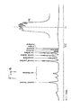
- the pre-column 2 provides coarse preliminary separation as shown by the diagrammatic curve PC in Figure 4. This curve gives an idea of what would be obtained from an analysis detector (such as the detector 6) placed at the outlet from the pre- column 2. This initial separation serves to ensure that only those light components which are to be analyzed are, in fact, admitted into the analysis column 4 (the right-hand portion of the curve PC drawn in solid lines), while the remaining heavier components are not admitted thereto (left-hand portion of the curve PC drawn in dashed lines).
- Said light components are mixed together again on arriving in the chamber 3 by the porous stopper 14 which they must pass through, and by the volume given to said chamber which is selected to be relatively large with regard to the gaseous volume of the vaporized portion of the initial substance. All of these components thus arrive simultaneously at the inlet 4a of the analysis column 4 and enter said column together.
- the switching valve is operated to set up the connections shown in dashed lines.
- the flow direction of the carrier gas through the pre-column is reversed, thereby backwashing said heavier components from the pre- column into the injector 1 from which they are finally rejected to the atmosphere via the ducts 11 and 26 and via the valve 27.
- This reversal of the gas flow direction serves firstly to avoid polluting the column 4 with the unwanted portion of the sample, and secondly to backwash not only the pre-column 2, but also the chamber 3 and the injector 1, thereby cleaning them thoroughly so that said items do not accumulate unwanted matter and can therefore be used many times over without requiring any other form of cleaning, or replacement.
- the residue of non- vaporized heavy components from each sample inserted into the injector is relieved of its lighter components which are not wanted for analysis purposes and can therefore remain in the injector during following analyses, thereby reducing the frequency with which the sample-receiving glass tube 10 needs to be replaced.
- the division ratio corresponds to the ratio of the operating flow rates of the two columns 2 and 4, with the operating flow rate of the column 4 (which is a capillary column) being very much less than that of the pre-column 2.
- the light components admitted into the analysis column 4 flow therealong while being subjected to fine chromatographic separation as shown up by the detector 6 in the form of a chart similar to that shown in Figure 4, which corresponds to an analysis of the C 6 - components of a crude petroleum oil.
- An internal reference (a known quantity of acetone) is added to the sample inserted into the apparatus and produces a (shaded) peak between two peaks of sample components, thereby making quantitative analysis of the sample possible.
- Highly viscous samples may be diluted in a solvent in order to facilitate taking samples using the chromatographic syringe 30.
- the solvent should be chosen so that the time it requires for being eluted along the pre-column 2 is greater than the time required for the slowest component of interest, so that the solvent remains in the portion which is not admitted into the analysis column 4, and which therefore does not appear on the chromatogram.
- an apparatus in accordance with the invention for performing chromatographic analysis of petroleum products may have its main component parts selected to have the following dimensions and characteristics.
- Pre-column 2 a stainless steel column which is about 1.5 meters (m) long, having a diameter of about 3 mm, filled with "Chromosorb PAW” medium (having a granulometry of 80 to 100 mesh, i.e. about 0.18 to about 0.15 mm), impregnated with 15% “SE30" silicon to constitute the stationary liquid phase, and operating at a flow rate of about 20 to 40 cm 3 /min. It is capable of receiving an inlet gas sample having a volume of about 1 cm 3 (5 mm 3 in the liquid state), mixed with the carrier gas flow.
- Intermediate chamber 3 tubular chamber 45 mm long with a diameter of 4 mm containing a 20 mm long quartz wool plug 14 in its half closest to its inlet connected to the pre-column 2, with the distance between the inlet end 4a to the column 4, and the adjacent end face of the plug 14 being 10 mm.
- the inside volume of such a chamber is suitable for the pre-column having a volume of substance injected thereto corresponding to 1 cm 3 of gas or 5 mm 3 of liquid.
- Analysis column 4 a stainless steel capillary column having a length of 100 m, a bore whose inside diameter is equal to 0.25 mm and is lined with a 0.2 pm thick film of "Squalane" constituting the stationary liquid phase, and operating at a flow rate of about 0.8 to 1.5 cm 3 /min. (i.e. about one-thirtieth of the flow rate applicable to the pre- column).
Description
- The present invention relates to a method of analysis by gas chromatography, in which a liquid substance to be analyzed, more particularly a crude petroleum oil, is put into gaseous form, and is conveyed by means of a carrier gas along an analysis column system for chromatographic separation, and the lighter components of said substance are detected as they leave said column system in succession. The invention also relates to an apparatus for carrying out such method.
- Heretofore, petroleum liquids have generally been analyzed in the laboratory, or on site in a laboratory cabin which reproduces laboratory conditions. The liquid is initially separated into a light portion and a heavy portion by means of a distillation apparatus. The light portion is analyzed by means of a gas chromatograph, whereas only two or three overall physical measurements are used to characterize the heavy portion (e.g. molar mass, density, ...). This method suffers from the drawback of requiring additional apparatus (for distillation) which is difficult and lengthy to put into operation. Further, the operations of recovering and measuring the various products may give rise to additional sources of error. In some laboratories, the liquid is injected directly into a gas chromatograph whose circuit comprises an injector, a short duct, and an analysis column. Quantitative analysis is performed by means of the method using an internal standard. This method makes it possible to avoid prior separation, but the system becomes polluted very quickly if heavy oils are injected therein, since the intermediate components migrate slowly but irremediably along the short duct and thus reach the analysis column.
- In order to overcome this drawback, it has been proposed in U.S. Patent No 3,030,798 to Lichten- fels a two-stage process using two packed columns connected in series. In this known technique, the fluid mixture to be analyzed is initially injected into the first column and carrier gas is flowed through the first and the second column. When all the components of interest i.e. the lighter components have emerged from the first column, the direction of flow of the carrier gas in the first column is reversed while it remains unchanged in the second column. The effect is to remove from the first column the heavier components which remain therein, and once this backflushing is completed, the first column is in condition for receiving another charge to be analyzed. At the same time, the analysis continues in the second column.
- The system described in this patent is disadvantageous in that the flow of carrier gas is controlled by valves which are part of the circuit through which the substance to be analyzed is circulated. This may give rise to leaks and creates "dead volumes" detrimental to the accuracy of the analysis.
- In US patent US-A-3 169 389 (Green) a gas chromatography system is described comprising a short precolumn and a second column. A backflush valve is located between the two columns in order to handle crude oil analysis. A vapor divider, when used, may be placed between introduction means and the second column. The backflush valve is shown to be a part of the circuit through which the sample to be analysed is circulated together with the carrier gas.
- European patent EP-A-0 051 778 describes an injection device for on-column direct injection of liquid samples. A splitting device placed between a first capillary column length and a gas chromatographic column is used for discharging a given amount of the sample before analysis. This system does not include any backflushing device and cannot be used for analysing crude oil.
- US patent US-A-3 444 772 (Roof) describes a system suitable for gas analysis but not for crude oil analysis. This system comprises two capillary columns which operate at similar flow rates. A blending chamber is used to inject a carrier II, a flow of carrier gas being maintained permanently into the blending chamber. This document does not show any means for discharging a given amount of the sample to be analysed through the blending chamber to the atmosphere.
- The drawbacks of the prior art systems are overcome by the method and apparatus of the invention as claimed in
claims 1 and 5. - An implementation of the invention is described by way of example with reference to the accompanying drawings, in which:
- Figure 1 is a diagram showing the structure of a chromatographic apparatus in accordance with the invention;
- Figures 2 and 3 are longitudinal sections on a larger scale respectively through the injector and through the intermediate chamber of the figure 1 apparatus; and
- Figure 4 is an example of a chromatogram obtained during analysis of a petroleum substance.
- The apparatus shown diagrammatically in Figure 1 comprises an analysis circuit, or main circuit, along which at least some of the components of the substance to be analyzed are made to flow, and an auxiliary circuit for the carrier gas which is used to transport the components of said substance in gaseous form. The main circuit comprises an injector 1, a first
chromatographic column 2, referred to below as the pre-column, anintermediate chamber 3, a second chromatographic column 4, referred to below as the analysis column, adevice 5 for adding carrier gas, and an analysis detector 6, with all of said items being connected in series. - The injector 1 (see Figure 2) is intended to vaporize the components of the substance to be analyzed and to inject them into the pre-column 2. It comprises an
elongate enclosure 7 which extends horizontally and is closed at one end by a septum 8 (i.e. a disk of resilient material capable of being pierced by a needle). The septum is held in place by acap 9. Theother end 7a of theenclosure 7 is connected to the inlet of the pre-column 2. Aremovable tube 10 of borosilicate glass is disposed horizontally inside the enclosure having one end connected in sealed manner to theoutlet end 7a of theenclosure 7 and having its other end stopping short of theseptum 8, thereby putting both portions of the inside volume of theenclosure 7 as separated by thetube 10 into communication with each other at said end. Aduct 11 is connected to theenclosure 7 close to itsend 7a for injecting a carrier gas for transporting the fluid to be analyzed towards said main circuit. Theenclosure 7 is surrounded byheater elements 12 for raising it to a high enough temperature to vaporize the components of the substance to be analyzed as inserted into the injector. - The pre-column 2 is a packed chromatographic column containing an inert support impregnated with a liquid for cooperating with the gaseous components to be separated. The purpose of the pre-column 2 is to separate the lighter components of the fluid to be analyzed from the heavier portion vaporized in the injector 1, but which is not wanted for analysis purposes.
- The
intermediate chamber 3 is constituted (see Figure 3) by atube 13 containing aporous body 14 such as a plug of quartz wool extending over a portion of its length adjacent to itsend 13a by which it is connected to the pre-column 2. The inlet end 4a of the analysis column 4 penetrates into thetube 13 via theopposite end 13b thereof in order to sample the gaseous fluid in the central region of thenon-turbulent zone 28 left free inside thetube 13 by theporous body 14. Aduct 15 is also connected to said end of thetube 13 in order to remove a portion of the gaseous fluid coming from the pre-column 2. The first function of thechamber 3 is to divide the gas flow which it receives from the pre-column 2 into two portions and to apply a gas flow to the analysis column 4 which is compatible with the capabilities thereof, with the remainder of the flow being exhausted to the atmosphere via theduct 15. - The analysis column 4 is a very long capillary tube of the "open tube" type which serves to separate the components selected by the pre-
column 2 for analysis purposes, with analysis being performed by means of the detector 6 which is constituted by a thermal conductivity cell or "katharometer". In order to ensure that the conductivity cell operates under good conditions, in spite of the very low flow rate along the capillary column 4, the column opens out into a mixing chamber belonging to thedevice 5 for adding in a flow of carrier gas received via aduct 16, withsaid duct 16 including areference detector 17 similar to the analysis detector 6. Thecolumns 2 and 4, theintermediate chamber 3, the carriergas adding device 5, and thedetectors 6 and 17 are all placed in aconstant temperature enclosure 31, which may be a simple oven which is isothermally regulated by inertia. - The auxiliary circuit is a pneumatic circuit comprising an inlet for the
carrier gas 18 suitable for connection to a cylinder of compressed gas (e.g. helium). Thisinlet 18 is connected via aduct 19 including apressure regulator 20 to theduct 15 which is connected to thedivision chamber 3, and via aduct 21 fitted with aflow rate regulator 22 and a four-path valve 23 to theduct 11 which is connected to the injector 1 and via aduct 24 including amicrometer valve 25 for adjusting a flow rate limit to thedevice 5 for adding carrier gas via thedetector 17 and theduct 16. Theduct 15 of thedivision chamber 3 is connected not only to theduct 19 but also via the four-path valve 23 to aduct 26 leading to the atmosphere via an adjustable flowrate limiting valve 27. - The above-described connections between the
ducts valve 23 correspond to the position shown of its moving switch member, which position interconnects 11 to 21 and 15 to 26 as shown by solid lines. When this switch element is rotated through 90°, it then interconnects 15 to 21 and 11 to 26, as indicated by dashed lines. - It is to be pointed out that the path through the
elements - The operation of the apparatus and the procedure for using it are described below.
- A
drop 29 of substance to be analyzed is inserted into the glass tube of the injector 1 by passing asyringe 30 through theseptum 8 which is pierced by the needle of the syringe. This substance is a crude oil, i.e. a liquid mixture of hydrocarbons CnHm. The lightest components of this mixture are to be analyzed, which typically means components with 1 < n < 7. If the substance is too thick in consistency, it may be dissolved in a diluent chosen in such a way as to avoid disturbing the results of the chromatographic analysis. - The
heater element 12 of the injector 1 sets up a temperature therein such that all of the analytically interesting components of the mixture are vaporized (the heaviest components may remain in thetube 10 in liquid form, thus separating them out early). Thevalve 23 is put in a position where it sets up the connections shown in solid lines and causes carrier gas to flow through the injector 1, the pre-column 2, and theintermediate chamber 3 in the direction indicated by solid arrows. This flow of gas coming from theinlet 18 thus passes at a constant flow rate fixed by theflow rate regulator 22 along theducts tube 10 and the injector 1, the pre-column 2, thechamber 3, and theducts adjustable outlet valve 27. Suitable adjustment of theoutlet valve 27 raises the pressure in thechamber 3 to a value which is higher than atmospheric pressure and which is stabilized by thepressure regulator 20. - The flow of carrier gas set up in this way causes the vaporized components of the substance to be analyzed to circulate along the
pre-column 2. Thepre-column 2 provides coarse preliminary separation as shown by the diagrammatic curve PC in Figure 4. This curve gives an idea of what would be obtained from an analysis detector (such as the detector 6) placed at the outlet from the pre-column 2. This initial separation serves to ensure that only those light components which are to be analyzed are, in fact, admitted into the analysis column 4 (the right-hand portion of the curve PC drawn in solid lines), while the remaining heavier components are not admitted thereto (left-hand portion of the curve PC drawn in dashed lines). Said light components are mixed together again on arriving in thechamber 3 by theporous stopper 14 which they must pass through, and by the volume given to said chamber which is selected to be relatively large with regard to the gaseous volume of the vaporized portion of the initial substance. All of these components thus arrive simultaneously at the inlet 4a of the analysis column 4 and enter said column together. At an instant tc (as experimentally determined during earlier tests), all of the interesting components in the range C, to Cn (and preferably including one or two of the next components, by way of precaution) have entered the analysis column 4 and are also to be found in thechamber 3, whereas the heavier components which are not to be analyzed individually and which correspond to the left-hand portion of the curve PC, still remain in thechamber 3 or have not yet left thepre-column 2. - At this moment, the switching valve is operated to set up the connections shown in dashed lines. As a result the flow direction of the carrier gas through the pre-column is reversed, thereby backwashing said heavier components from the pre- column into the injector 1 from which they are finally rejected to the atmosphere via the
ducts valve 27. This reversal of the gas flow direction serves firstly to avoid polluting the column 4 with the unwanted portion of the sample, and secondly to backwash not only thepre-column 2, but also thechamber 3 and the injector 1, thereby cleaning them thoroughly so that said items do not accumulate unwanted matter and can therefore be used many times over without requiring any other form of cleaning, or replacement. In particular, the residue of non- vaporized heavy components from each sample inserted into the injector is relieved of its lighter components which are not wanted for analysis purposes and can therefore remain in the injector during following analyses, thereby reducing the frequency with which the sample-receivingglass tube 10 needs to be replaced. - During the initial operating period prior to the switch-over instant t,,, only a fraction of the gas flow leaving the
pre-column 2 is admitted into the column 4, by virtue of the division effect provided by thechamber 3, with the excess portion of said gas mixture (components to be analyzed plus carrier gas) being rejected to the atmosphere via theducts adjustable valve 27. The division ratio corresponds to the ratio of the operating flow rates of the twocolumns 2 and 4, with the operating flow rate of the column 4 (which is a capillary column) being very much less than that of thepre-column 2. - The light components admitted into the analysis column 4 flow therealong while being subjected to fine chromatographic separation as shown up by the detector 6 in the form of a chart similar to that shown in Figure 4, which corresponds to an analysis of the C6- components of a crude petroleum oil. An internal reference (a known quantity of acetone) is added to the sample inserted into the apparatus and produces a (shaded) peak between two peaks of sample components, thereby making quantitative analysis of the sample possible.
- Highly viscous samples may be diluted in a solvent in order to facilitate taking samples using the
chromatographic syringe 30. The solvent should be chosen so that the time it requires for being eluted along thepre-column 2 is greater than the time required for the slowest component of interest, so that the solvent remains in the portion which is not admitted into the analysis column 4, and which therefore does not appear on the chromatogram. - It should be observed that the operating regime of the column 4 is absolutely uniform and stable throughout both operating stages (as distinguished by switching over the valve 23) since the pressure applied to the inlet 4a of said column (i.e. the pressure in the chamber 3) is kept permanently constant by the
pressure regulator 20 whose output is connected via theducts - Pre-column 2: a stainless steel column which is about 1.5 meters (m) long, having a diameter of about 3 mm, filled with "Chromosorb PAW" medium (having a granulometry of 80 to 100 mesh, i.e. about 0.18 to about 0.15 mm), impregnated with 15% "SE30" silicon to constitute the stationary liquid phase, and operating at a flow rate of about 20 to 40 cm3/min. It is capable of receiving an inlet gas sample having a volume of about 1 cm3 (5 mm3 in the liquid state), mixed with the carrier gas flow.
- Intermediate chamber 3: tubular chamber 45 mm long with a diameter of 4 mm containing a 20 mm long
quartz wool plug 14 in its half closest to its inlet connected to thepre-column 2, with the distance between the inlet end 4a to the column 4, and the adjacent end face of theplug 14 being 10 mm. The inside volume of such a chamber is suitable for the pre-column having a volume of substance injected thereto corresponding to 1 cm3 of gas or 5 mm3 of liquid. - Analysis column 4: a stainless steel capillary column having a length of 100 m, a bore whose inside diameter is equal to 0.25 mm and is lined with a 0.2 pm thick film of "Squalane" constituting the stationary liquid phase, and operating at a flow rate of about 0.8 to 1.5 cm3/min. (i.e. about one-thirtieth of the flow rate applicable to the pre- column).
Claims (8)
Applications Claiming Priority (2)
| Application Number | Priority Date | Filing Date | Title |
|---|---|---|---|
| FR8607323A FR2599152B1 (en) | 1986-05-22 | 1986-05-22 | PROCESS AND APPARATUS FOR CHROMATOGRAPHIC ANALYSIS, PARTICULARLY FOR PETROLEUM LIQUIDS |
| FR8607323 | 1986-05-22 |
Publications (2)
| Publication Number | Publication Date |
|---|---|
| EP0247929A1 EP0247929A1 (en) | 1987-12-02 |
| EP0247929B1 true EP0247929B1 (en) | 1990-07-11 |
Family
ID=9335501
Family Applications (1)
| Application Number | Title | Priority Date | Filing Date |
|---|---|---|---|
| EP87401151A Expired - Lifetime EP0247929B1 (en) | 1986-05-22 | 1987-05-22 | Method and apparatus for chromatographic analysis, in particular of petroleum liquids |
Country Status (4)
| Country | Link |
|---|---|
| US (1) | US4864843A (en) |
| EP (1) | EP0247929B1 (en) |
| DE (1) | DE3763624D1 (en) |
| FR (1) | FR2599152B1 (en) |
Families Citing this family (9)
| Publication number | Priority date | Publication date | Assignee | Title |
|---|---|---|---|---|
| EP0654667A1 (en) * | 1993-11-05 | 1995-05-24 | The Regents of The University of Michigan | Gas chromatography systems |
| US5933357A (en) * | 1996-09-13 | 1999-08-03 | The Perkin-Elmer Corporation | Backflushing system for gas chromatography |
| IT1303451B1 (en) * | 1998-09-23 | 2000-11-06 | Eurovector S P A | METHOD AND DEVICES TO IMPROVE THE FLASH COMBUSTION DYNAMIC REACTION COUPLED WITH GAS CHROMATOGRAPHY FOR ANALYSIS |
| NL1012127C2 (en) | 1999-05-21 | 2000-11-23 | Sgt Exploitatie Bv | Assembly for desorbing sampling tubes, as well as an adapter and sampling tubes apparently intended for such an assembly, as well as a kit of parts for forming such an assembly. |
| WO2005111600A1 (en) * | 2004-05-04 | 2005-11-24 | Nederlandse Organisatie Voor Toegepast-Natuurwetenschappelijk Onderzoek Tno | Method of analysis using chromatographic pre-separation |
| US20090158820A1 (en) * | 2007-12-20 | 2009-06-25 | Schlumberger Technology Corporation | Method and system for downhole analysis |
| EP2402746A1 (en) | 2010-06-30 | 2012-01-04 | Services Pétroliers Schlumberger | Injector and method for injecting a sample into a chromatography column |
| CA2874395A1 (en) | 2012-05-24 | 2013-12-19 | Douglas H. Lundy | Threat detection system having multi-hop, wifi or cellular network arrangement of wireless detectors, sensors and sub-sensors that report data and location non-compliance, and enable related devices while blanketing a venue |
| RU2681665C1 (en) * | 2017-11-14 | 2019-03-12 | Игорь Геннадиевич Лапшин | Method of chromatographic analysis of mixture of hydrocarbons and gas chromatography for its implementation |
Citations (3)
| Publication number | Priority date | Publication date | Assignee | Title |
|---|---|---|---|---|
| US3169389A (en) * | 1960-06-16 | 1965-02-16 | Standard Oil Co | Analysis by gas chromatography and apparatus therefor |
| US3444722A (en) * | 1966-09-09 | 1969-05-20 | Phillips Petroleum Co | Device for supplying carrier gas to transport eluted portion of sample and to backflush chromatographic column |
| EP0051778A2 (en) * | 1980-11-06 | 1982-05-19 | CARLO ERBA STRUMENTAZIONE S.p.A. | A device for vaporization injection in a gas-chromatographic column |
Family Cites Families (9)
| Publication number | Priority date | Publication date | Assignee | Title |
|---|---|---|---|---|
| US3030798A (en) * | 1956-11-02 | 1962-04-24 | Gulf Research Development Co | Chromatographic process and apparatus |
| FR1269160A (en) * | 1960-06-27 | 1961-08-11 | Cie De Raffinage Shell Berre | Improvements to chromatographic analysis devices |
| FR1322663A (en) * | 1962-05-21 | 1963-03-29 | Perkin Elmer Corp | Gas chromatography apparatus |
| NL288659A (en) * | 1963-02-01 | |||
| US3607075A (en) * | 1968-08-09 | 1971-09-21 | Mc Donnell Douglas Corp | Instrument and method for analyzing complex substances |
| FR2063575A5 (en) * | 1969-10-22 | 1971-07-09 | Carbonique | Analysis of impurities in gases |
| FR2206858A5 (en) * | 1972-11-10 | 1974-06-07 | Raffinage Cie Francaise | |
| US4035168A (en) * | 1974-07-24 | 1977-07-12 | The Regents Of The University Of California | Nonreactive inlet splitter for gas chromatography and method |
| US4287752A (en) * | 1979-08-03 | 1981-09-08 | Standard Oil Co. (Indiana) | Apparatus and method for analyzing the hydrocarbon type composition of gasoline |
-
1986
- 1986-05-22 FR FR8607323A patent/FR2599152B1/en not_active Expired
-
1987
- 1987-05-22 DE DE8787401151T patent/DE3763624D1/en not_active Expired - Fee Related
- 1987-05-22 EP EP87401151A patent/EP0247929B1/en not_active Expired - Lifetime
-
1988
- 1988-11-03 US US07/267,641 patent/US4864843A/en not_active Expired - Lifetime
Patent Citations (3)
| Publication number | Priority date | Publication date | Assignee | Title |
|---|---|---|---|---|
| US3169389A (en) * | 1960-06-16 | 1965-02-16 | Standard Oil Co | Analysis by gas chromatography and apparatus therefor |
| US3444722A (en) * | 1966-09-09 | 1969-05-20 | Phillips Petroleum Co | Device for supplying carrier gas to transport eluted portion of sample and to backflush chromatographic column |
| EP0051778A2 (en) * | 1980-11-06 | 1982-05-19 | CARLO ERBA STRUMENTAZIONE S.p.A. | A device for vaporization injection in a gas-chromatographic column |
Also Published As
| Publication number | Publication date |
|---|---|
| FR2599152B1 (en) | 1989-07-28 |
| EP0247929A1 (en) | 1987-12-02 |
| DE3763624D1 (en) | 1990-08-16 |
| FR2599152A1 (en) | 1987-11-27 |
| US4864843A (en) | 1989-09-12 |
Similar Documents
| Publication | Publication Date | Title |
|---|---|---|
| Grob et al. | On-column injection on to glass capillary columns | |
| EP1774315B1 (en) | System for regulating fluid flowing through chromatographic column | |
| EP0551594B1 (en) | High efficiency packed column supercritical fluid chromatography | |
| EP0661537A2 (en) | Apparatus for gas chromatography | |
| US4766760A (en) | Method of chromatographic analysis of a mixture of liquid substances and a gas chromatograph for carrying out the method | |
| US5338514A (en) | Vented capillary gas chromatography apparatus | |
| EP0247929B1 (en) | Method and apparatus for chromatographic analysis, in particular of petroleum liquids | |
| JPH01127954A (en) | Method and apparatus for measuring isotope composition | |
| US3425807A (en) | Pyrolysis system | |
| Gordon et al. | Comparison of state-of-the-art column switching techniques in high resolution gas chromatography | |
| US4186607A (en) | Liquid sample dilution system | |
| EP0547282B1 (en) | Analytic separation arrangement and method for the analysis of chemical samples | |
| JPH0431352B2 (en) | ||
| US4442217A (en) | Sample injection | |
| US3057692A (en) | Pyrolytic instrument | |
| EP0654667A1 (en) | Gas chromatography systems | |
| US4873058A (en) | Flow divider for gas chromatographs | |
| EP0127908A2 (en) | Method and apparatus for analyzing a hydrocarbon sample | |
| Ligon Jr et al. | Some experiences with two-dimensional gas chromatography/mass spectrometry | |
| EP0406757B1 (en) | Method for chromatographic separation | |
| Hinshaw Jr | Modern inlets for capillary gas chromatography | |
| JPH06242095A (en) | Simultaneous quantitative analysis of kerosene, methanol, btx and mtbe in gasoline | |
| Kern et al. | Precision of an automated all‐glass capillary gas chromatography system with an electron capture detector for the trace analysis of estrogens | |
| Hwu et al. | Instrumentation and separation results of medium pressure liquid chromatography | |
| Stavinoha | Hydrocarbon-Type Analysis of Gasoline Using Stabilized Olefin Absorption and Gas Chromatography |
Legal Events
| Date | Code | Title | Description |
|---|---|---|---|
| PUAI | Public reference made under article 153(3) epc to a published international application that has entered the european phase |
Free format text: ORIGINAL CODE: 0009012 |
|
| AK | Designated contracting states |
Kind code of ref document: A1 Designated state(s): DE ES FR GB IT NL |
|
| 17P | Request for examination filed |
Effective date: 19880524 |
|
| 17Q | First examination report despatched |
Effective date: 19881011 |
|
| GRAA | (expected) grant |
Free format text: ORIGINAL CODE: 0009210 |
|
| AK | Designated contracting states |
Kind code of ref document: B1 Designated state(s): DE ES FR GB IT NL |
|
| REF | Corresponds to: |
Ref document number: 3763624 Country of ref document: DE Date of ref document: 19900816 |
|
| ITF | It: translation for a ep patent filed |
Owner name: DOTT. FRANCO CICOGNA |
|
| PG25 | Lapsed in a contracting state [announced via postgrant information from national office to epo] |
Ref country code: ES Free format text: LAPSE BECAUSE OF FAILURE TO SUBMIT A TRANSLATION OF THE DESCRIPTION OR TO PAY THE FEE WITHIN THE PRESCRIBED TIME-LIMIT Effective date: 19901022 |
|
| ET | Fr: translation filed | ||
| PLBE | No opposition filed within time limit |
Free format text: ORIGINAL CODE: 0009261 |
|
| STAA | Information on the status of an ep patent application or granted ep patent |
Free format text: STATUS: NO OPPOSITION FILED WITHIN TIME LIMIT |
|
| ITTA | It: last paid annual fee | ||
| 26N | No opposition filed | ||
| PGFP | Annual fee paid to national office [announced via postgrant information from national office to epo] |
Ref country code: NL Payment date: 19920531 Year of fee payment: 6 |
|
| PGFP | Annual fee paid to national office [announced via postgrant information from national office to epo] |
Ref country code: DE Payment date: 19920619 Year of fee payment: 6 |
|
| PG25 | Lapsed in a contracting state [announced via postgrant information from national office to epo] |
Ref country code: NL Effective date: 19931201 |
|
| NLV4 | Nl: lapsed or anulled due to non-payment of the annual fee | ||
| PG25 | Lapsed in a contracting state [announced via postgrant information from national office to epo] |
Ref country code: DE Effective date: 19940201 |
|
| REG | Reference to a national code |
Ref country code: GB Ref legal event code: IF02 |
|
| PGFP | Annual fee paid to national office [announced via postgrant information from national office to epo] |
Ref country code: FR Payment date: 20020522 Year of fee payment: 16 |
|
| PG25 | Lapsed in a contracting state [announced via postgrant information from national office to epo] |
Ref country code: FR Free format text: LAPSE BECAUSE OF NON-PAYMENT OF DUE FEES Effective date: 20040130 |
|
| REG | Reference to a national code |
Ref country code: FR Ref legal event code: ST |
|
| PGFP | Annual fee paid to national office [announced via postgrant information from national office to epo] |
Ref country code: GB Payment date: 20040519 Year of fee payment: 18 |
|
| PG25 | Lapsed in a contracting state [announced via postgrant information from national office to epo] |
Ref country code: IT Free format text: LAPSE BECAUSE OF NON-PAYMENT OF DUE FEES;WARNING: LAPSES OF ITALIAN PATENTS WITH EFFECTIVE DATE BEFORE 2007 MAY HAVE OCCURRED AT ANY TIME BEFORE 2007. THE CORRECT EFFECTIVE DATE MAY BE DIFFERENT FROM THE ONE RECORDED. Effective date: 20050522 Ref country code: GB Free format text: LAPSE BECAUSE OF NON-PAYMENT OF DUE FEES Effective date: 20050522 |
|
| GBPC | Gb: european patent ceased through non-payment of renewal fee |
Effective date: 20050522 |