EP0247883A2 - A digital remote control transmission apparatus - Google Patents
A digital remote control transmission apparatus Download PDFInfo
- Publication number
- EP0247883A2 EP0247883A2 EP87304747A EP87304747A EP0247883A2 EP 0247883 A2 EP0247883 A2 EP 0247883A2 EP 87304747 A EP87304747 A EP 87304747A EP 87304747 A EP87304747 A EP 87304747A EP 0247883 A2 EP0247883 A2 EP 0247883A2
- Authority
- EP
- European Patent Office
- Prior art keywords
- code
- pulses
- remote control
- data
- transmission apparatus
- Prior art date
- Legal status (The legal status is an assumption and is not a legal conclusion. Google has not performed a legal analysis and makes no representation as to the accuracy of the status listed.)
- Granted
Links
Images


Classifications
-
- G—PHYSICS
- G08—SIGNALLING
- G08C—TRANSMISSION SYSTEMS FOR MEASURED VALUES, CONTROL OR SIMILAR SIGNALS
- G08C19/00—Electric signal transmission systems
- G08C19/16—Electric signal transmission systems in which transmission is by pulses
- G08C19/28—Electric signal transmission systems in which transmission is by pulses using pulse code
Definitions
- the present invention relates to a digital remote control apparatus, and more particularly to an improvement in the transmission format of such an apparatus.
- Such a kind of digital remote control apparatus is used as a remote control apparatus for conducting channel setting, volume adjustment, ON/OFF of the power supply, tape play, tape stop, fast forwarding, rewinding, setting (an advanced programming) of start/stop time, date, channel, and days of the week of video or audio recording in such as a television, a video tape recorder, and an audio tape recorder. It is also used in the selection of cooling, heating, or dehumidification, the setting of temperature and time, ON/OFF of the power supply such as in an air conditioner. In summary, it is used as a remote control apparatus in such as electric appliances, automobiles, robots, and electro medical equipments.
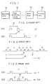
- Figures l and 2 show block constructions of a general digital remote control system.
- the reference numeral 3l designates a transmitting circuit including a key input read circuit ll, a code modulation circuit l2, a timing generator l3, and an oscillator l4.
- the reference numeral 32 designates a receiving circuit including a preamplifier l8, and a remote control signal demodulation circuit l9.
- the reference numeral 33 designates a light emitting diode or other light emitting element.
- the reference numeral 34 designates a photo diode or other light receiving element.
- the reference numeral l0 designates a key matrix for inputting information to the key input read circuit ll of the transmitting circuit 3l.
- the reference numeral l5 designates a driver circuit comprising a transistor which receives the information from the code modulation circuit l2 of the transmitting circuit 3l and makes a current in accordance with the information flow through the light emitting element 33.
- the reference numeral l6 designates a light information transmitted from the light emitting element 33 to the light receiving element 34.
- the information to be sent out is input to the transmitting circuit 3l by the key matrix l0, and this is encoded by the transmitting circuit 3l, and this is modulated and transmitted in a light signal l6 by the light emitting diode 33.
- the transmitted light signal l6 is received by the photo diode 34, and this is demodulated by the receiving circuit 32 to decode the instruction.
- Figure 3 shows a transmission format in such a kind of transmission system which is already developed by the inventor.
- the distinction of one bit information "0" and “l” are conducted by the intervals 4l and 42 between the two subsequent pulses as shown in Figure 3. That is, the short time interval 4l from the rising up of the pulse to the rising up of the next pulse (in Figure 3(a)) corresponds to a bit "0", and the long time interval 42 of that ( Figure 3(b)) corresponds to a bit "l”.
- These information "0” and "l” of several bits are combined to constitute a word as shown in Figure 4, and the kinds of instructions are distinguished from each other on the basis of the data code of this word.
- one word 5 comprises a six bit construction, and in this figure the data bit of the word 5 is "0l0000".
- the code 6 designates the repetition period of the word 5.
- a digital remote control transmission apparatus for conducting a remote control of an apparatus to be controlled by sending a digital signal to the apparatus, which comprises: a transmission code of said digital signal comprising a custom code for distinguishing the apparatus to be controlled, an instruction code for operating said apparatus to be controlled, and a separation code for separating said two codes; the respective bits of said custom code and instruction code being data codes which are represented by the positions of data pulses inserted between synchronization pulses of a predetermined period; and said separation codes being codes which includes no data pulses inserted between two synchronization pulses.
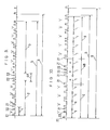
- Figure 6 shows a construction of the transmission code of a digital remote control transmission apparatus as an embodiment of the present invention.
- the reference numeral 2l designates a synchronization pulse of a predetermined period, and this synchronization pulse is made from the pulse which is output from the timing generator l3 by that pulse being applied to the code modulation circuit l2, which generator l3 receives pulses of a predetermined period from the oscillator l4 shown in Figure 2.
- the reference numeral 22 designates a data pulse inserted between the synchronization pulses 2l. For example, this data pulse is produced by that desired information from the key matrix l0 is read in into the key input read circuit ll, and synchronized with the timings of the timing pulses output from the timing generator l3 thereat, and that the synchronized data is input to the code modulation circuit l2.
- the reference numeral l designates a one bit period corresponding to the period between the synchronization pulses 2l.
- the reference numeral 2 designates a custom code for distinguishing the apparatus to be controlled (at the receiving side). In this embodiment this custom code is constituted in a four bit construction.
- the reference numeral 3 designates a data code for operating the apparatus to be controlled (instruction code). In this embodiment this data code is constituted in a six bit construction.
- the reference numeral 4 designates a separation code (separation period) for separating the custom code 2 and the data code 3, which is provided as a characteristics of the present invention. In this embodiment this separation code comprises a code in which data pulses are not inserted between the two synchronization pulses 2l.
- the reference numeral 5 designates a one word of the transmission code
- the reference numeral 6 designates a repetition period.
- the construction of the remote control system of the present embodiment is the same as those of Figures l and 2.
- the distinction of the bit "0" and “l” are made as follows. That is, when the period 23 or 25 from the rising up of the synchronization pulse to the rising up of the data pulse subsequent to the synchronization pulse (or from the falling down of the synchronization pulse to the falling down of the data pulse subsequent thereto) is l ms the bit is "0" ( Figure 7(a)), and when the former period is 2 ms the bit is "l” ( Figure 7(b)). Accordingly, the period l of the synchronization pulse 2l is 3 ms.
- the four bit custom code 2 (which is "l00l” in the example of Figure 6) is transmitted, and next the period including no data pulses (separation code) 4 is transmitted, and furthermore the six bit data code 3 (which is "ll00ll” in the example of Figure 6) is transmitted.
- the one word length of the transmission code 5 which has the same bit number is constant regardless of the number of the "0" (or "l") in the data.
- the data interpretation is easened.
- a noise 7l as shown in Figure 8 is inserted into the data of bit information "0" it becomes as such that two data pulses are inserted in a bit, and it is possible to prevent the malfunction of the receiving side because it is possible to judge them as noises easily at the receiving side.
- the transmission code 5 is separated into the custom code 2 and the data code (instruction code) 3, and the period (separation code) 4 representing the boundary therebetween is provided. Accordingly, even if the bit numbers of the whole of the transmission code are equal to each other, it is possible to produce code systems which do not interfere with each other by changing the bit numbers of the custom code and the data code. That is, it is possible to produce a plurality of independent remote control systems with the use of the transmission code having the same bit number.
- Figure 9 shows a construction of the transmission code of the second embodiment of the present invention.
- This second embodiment is different from the first embodiment only in the separation code 4A.
- This separation code 4A is constructed in such a manner that two data pulses 22 are inserted between two synchronization pulses 2l.
- the four bit custom code 2 (which is "l00l” in the example of figure 9) is transmitted as similarly as the first embodiment, and next a separation code 4A including two data pulses is transmitted, and the six bit data code 3 (which is "ll00ll” in the example of Figure 9) is transmitted.
- the transmission code 5 is separated into the custom code 2 and the data code 3 by providing the separation code 4A as a boundary, it is possible to produce code systems which do not interfere with each other even if the bit numbers of the whole of the transmission code are equal to each other by changing the bit numbers of the custom code and the data code. That is, it is possible to produce a plurality of code systems with the use of the transmission codes having the same bit number.
- Figure l0 shows a construction of a transmission code as a third embodiment of the present invention.
- This third embodiment is different from the first embodiment only in the separation code 4B.
- This separation code 4B is constituted by the two periods A in which data pulses are not inserted between the two synchronization pulses 2l and the period B in which two data pulses 22 are inserted between two synchronization pulses 2l, which period B is inserted between the two periods A.
- four bit custom code 2 (which is "l00l” in the example of Figure l0) is at first transmitted as similarly as the first embodiment, and subsequent thereto a separation code 4B for separating the custom code and the instruction code is transmitted, and furthermore five bit instruction code 3 (which is "0l00l” in the example of Figure l0) is transmitted.
- one word length of the transmission code 5 having the same bit number is constant regardless of the number of the data "0" (or "l").
- the transmission code 5 is separated into the custom code 2 and the instruction code 3 and a separation code 4B representing the boundary therebetween is provided, even if the bit number of the whole of the transmission code are equal to each other, it is possible to produce code systems which do not interfere with each other by changing the bit number of the custom code 2 and the instruction code 3. That is, it is possible to produce a plurality of code systems with the use of the transmission code having the same bit number.
- the separation code 4B representing the boundary between the custom code 2 and the instruction code 3 is constituted by the period A and the period B having two data pulses between the two synchronization pulses, it is possible to produce code systems which, having different combinations of the periods A and B, do not interfere with each other.
- the separation code 4B comprises two periods of A and a period of B in sequence of "ABA", but in this third embodiment it is possible to produce 6 kinds of code systems by only using the separation code 4B in a case where the separation code 4B is a 3 bit code comprising two kinds of periods. It is possible to increase the number of the periods constituting the period 4B in order to produce a larger number of code systems which do not interfere with each other.
- the period of the synchronization pulse is 3 ms
- the time length between the rising ups of the synchronization pulse and the data pulse which corresponds to the bit "0" is l ms
- that which corresponds to the bit "l” is 2 ms
- these time lengths can be set to any values on a condition that the time lengths may be distinguished from each other as those representing the bit "0" and "l", respectively.
- the synchronization pulse and the data pulse may be frequency modulated by a particular frequency e.g. 38 KHz so as to conduct a transmission in a narrow frequency band, whereby the anti-noise characteristics of the transmission system is enhanced.
- a leading pulse having a long pulse width may be inserted before the transmission code so that the arrival of the transmission signal may be easily detected at the receiving side.
- the pulse widths of the synchronization pulse 2l and the data pulse 22 may be differentiated so as to ease the distinction of the both pulses at the receiving side.
- bit numbers of the custom code and the data code may be differentiated so as to ease the distinction of the both codes at the receiving side.
- custom code 2 is transmitted before and the instruction code 3 is transmitted after, but the instruction code 3 can be transmitted before.
- the period 4 for separating the custom code 2 and the data code 3 comprises only one period of the synchronization pulse, but this may comprise an arbitrary number of periods.
- the separation code 4B for separating the custom code 2 and the instruction code 3 is made of only 3 periods of the synchronization pulses, but any number of periods can be used arbitrarily as already described.
- the period B which constitutes the separation code 4B in combination with the period A has two data pulses between the two synchronization pulses, but the number of the data pulses of the period B can be selected arbitrarily.
- the transmission code is constituted by a custom code, an instruction code, and a separation code in such a manner that the respective bit information of "0" or "l" of the custom code and the instruction code is represented by the position of the data pulse inserted between the synchronization pulses of a predetermined period, whereby the data interpretation is easened and anti-noise characteristics is enhanced. Furthermore, the interferences between remote control systems are prevented, and it is made possible to construct a plurality of independent remote control systems. This is quite effective in such a remote controllization.
Abstract
Description
- The present invention relates to a digital remote control apparatus, and more particularly to an improvement in the transmission format of such an apparatus.
- Such a kind of digital remote control apparatus is used as a remote control apparatus for conducting channel setting, volume adjustment, ON/OFF of the power supply, tape play, tape stop, fast forwarding, rewinding, setting (an advanced programming) of start/stop time, date, channel, and days of the week of video or audio recording in such as a television, a video tape recorder, and an audio tape recorder. It is also used in the selection of cooling, heating, or dehumidification, the setting of temperature and time, ON/OFF of the power supply such as in an air conditioner. In summary, it is used as a remote control apparatus in such as electric appliances, automobiles, robots, and electro medical equipments.
- Figures l and 2 show block constructions of a general digital remote control system. In the Figures the reference numeral 3l designates a transmitting circuit including a key input read circuit ll, a code modulation circuit l2, a timing generator l3, and an oscillator l4. The
reference numeral 32 designates a receiving circuit including a preamplifier l8, and a remote control signal demodulation circuit l9. Thereference numeral 33 designates a light emitting diode or other light emitting element. Thereference numeral 34 designates a photo diode or other light receiving element. The reference numeral l0 designates a key matrix for inputting information to the key input read circuit ll of the transmitting circuit 3l. The reference numeral l5 designates a driver circuit comprising a transistor which receives the information from the code modulation circuit l2 of the transmitting circuit 3l and makes a current in accordance with the information flow through thelight emitting element 33. The reference numeral l6 designates a light information transmitted from thelight emitting element 33 to thelight receiving element 34. - In such a system, the information to be sent out is input to the transmitting circuit 3l by the key matrix l0, and this is encoded by the transmitting circuit 3l, and this is modulated and transmitted in a light signal l6 by the
light emitting diode 33. The transmitted light signal l6 is received by thephoto diode 34, and this is demodulated by thereceiving circuit 32 to decode the instruction. - Figure 3 shows a transmission format in such a kind of transmission system which is already developed by the inventor. The distinction of one bit information "0" and "l" are conducted by the
intervals 4l and 42 between the two subsequent pulses as shown in Figure 3. That is, the short time interval 4l from the rising up of the pulse to the rising up of the next pulse (in Figure 3(a)) corresponds to a bit "0", and thelong time interval 42 of that (Figure 3(b)) corresponds to a bit "l". These information "0" and "l" of several bits are combined to constitute a word as shown in Figure 4, and the kinds of instructions are distinguished from each other on the basis of the data code of this word. In the example of Figure 4, oneword 5 comprises a six bit construction, and in this figure the data bit of theword 5 is "0l0000". Herein, thecode 6 designates the repetition period of theword 5. - In this transmission system, however, the length of the word becomes short or long dependent on the number of the bit information "0" (or "l") in a word, and this results in difficulty in the interpretation of data from the unawareness of the length of one word at the receiving side. Furthermore, as shown in Figure 5, when a noise 6l entered between the two pulses which represents the bit "l", this bit "l" is erroneously judged as "00" at the receiving side, leading to a malfunction. This causes a fatal defect in a remote control system.
- Furthermore, in order to avoid the interferences between remote control systems, there is a way in which systems are distinguished from each other by the custom code for distinguishing the apparatus to be controlled comprising initial two bits of a transmission data code, while the other subsequent four bits constitute an instruction code for operating the apparatus to be controlled, as in the example of Figure 4. However, in such a kind of technical field, various remote controls having various bit constructions are adopted, and therefore there is a possibility that there may arise interferences which unable the system to be used as a remote control system when the criteria for judging the bit as "0" or "l" are similar to each other in a case where the bit numbers are coincided with each other.
- It is an object of the present invention to provide an improved digital remote control transmission apparatus having a constant one word length and having superiority in anti-noise characteristics, and further capable of including a plurality of independent remote control systems.
- Other objects and advantages of the present invention will become apparent from the detailed description given hereinafter; it should be understood, however, that the detailed description and specific embodiment are given by way of illustration only, since various changes and modifications within the spirit and scope of the invention will become apparent to those skilled in the art from this detailed description.
- According to the present invention, there is provided a digital remote control transmission apparatus for conducting a remote control of an apparatus to be controlled by sending a digital signal to the apparatus, which comprises: a transmission code of said digital signal comprising a custom code for distinguishing the apparatus to be controlled, an instruction code for operating said apparatus to be controlled, and a separation code for separating said two codes; the respective bits of said custom code and instruction code being data codes which are represented by the positions of data pulses inserted between synchronization pulses of a predetermined period; and said separation codes being codes which includes no data pulses inserted between two synchronization pulses.
-
- Figure l is a diagram showing the brief block construction of a remote control system of the present invention and the prior art system;
- Figure 2 is a diagram showing the concrete example of the construction of Figure l;
- Figure 3 is a diagram for exemplifying the distinction of the bit information "0" and "l" of the prior art device;
- Figure 4 is a diagram showing the construction of the transmission code of the data signal of the prior art remote control transmission apparatus;
- Figure 5 is a diagram showing the state where noises are entered into the bit information "l" of the prior art device;
- Figure 6 is a diagram showing the construction of the transmission code of the data signal of the remote control transmission system of a first embodimemt of the present invention;
- Figure 7 is a diagram showing the distinction of the bit information "0" and "l" in the present invention;
- Figure 8 is a diagram showing the state where the noises are entered to the bit information "0" of the first embodiment;
- Figure 9 is a diagram showing the code construction of the remote control transmission system of a second embodiment of the present invention; and
- Figure l0 is a diagram showing the code construction of the remote control transmission system of a third embodiment of the present invention.
- In order to explain the present invention in detail, reference will be particularly made to Figure 6.
- Figure 6 shows a construction of the transmission code of a digital remote control transmission apparatus as an embodiment of the present invention.
- In Figure 6, the reference numeral 2l designates a synchronization pulse of a predetermined period, and this synchronization pulse is made from the pulse which is output from the timing generator l3 by that pulse being applied to the code modulation circuit l2, which generator l3 receives pulses of a predetermined period from the oscillator l4 shown in Figure 2. The
reference numeral 22 designates a data pulse inserted between the synchronization pulses 2l. For example, this data pulse is produced by that desired information from the key matrix l0 is read in into the key input read circuit ll, and synchronized with the timings of the timing pulses output from the timing generator l3 thereat, and that the synchronized data is input to the code modulation circuit l2. The reference numeral l designates a one bit period corresponding to the period between the synchronization pulses 2l. The reference numeral 2 designates a custom code for distinguishing the apparatus to be controlled (at the receiving side). In this embodiment this custom code is constituted in a four bit construction. The reference numeral 3 designates a data code for operating the apparatus to be controlled (instruction code). In this embodiment this data code is constituted in a six bit construction. Thereference numeral 4 designates a separation code (separation period) for separating the custom code 2 and the data code 3, which is provided as a characteristics of the present invention. In this embodiment this separation code comprises a code in which data pulses are not inserted between the two synchronization pulses 2l. Thereference numeral 5 designates a one word of the transmission code, and thereference numeral 6 designates a repetition period. Besides, the construction of the remote control system of the present embodiment is the same as those of Figures l and 2. In this embodiment, the distinction of the bit "0" and "l" are made as follows. That is, when theperiod - In this embodiment, at first the four bit custom code 2 (which is "l00l" in the example of Figure 6) is transmitted, and next the period including no data pulses (separation code) 4 is transmitted, and furthermore the six bit data code 3 (which is "ll00ll" in the example of Figure 6) is transmitted.
- Accordingly, the one word length of the
transmission code 5 which has the same bit number is constant regardless of the number of the "0" (or "l") in the data. For example, the one word length is 33.25 ms (= 3 ms × ll + 0.25 ms) when the pulse width of the synchronization pulse is 0.25 ms. Thus, the data interpretation is easened. Furthermore, even if a noise 7l as shown in Figure 8 is inserted into the data of bit information "0" it becomes as such that two data pulses are inserted in a bit, and it is possible to prevent the malfunction of the receiving side because it is possible to judge them as noises easily at the receiving side. - Furthermore, the
transmission code 5 is separated into the custom code 2 and the data code (instruction code) 3, and the period (separation code) 4 representing the boundary therebetween is provided. Accordingly, even if the bit numbers of the whole of the transmission code are equal to each other, it is possible to produce code systems which do not interfere with each other by changing the bit numbers of the custom code and the data code. That is, it is possible to produce a plurality of independent remote control systems with the use of the transmission code having the same bit number. - Figure 9 shows a construction of the transmission code of the second embodiment of the present invention. This second embodiment is different from the first embodiment only in the
separation code 4A. Thisseparation code 4A is constructed in such a manner that twodata pulses 22 are inserted between two synchronization pulses 2l. - Also in this second embodiment, at first the four bit custom code 2 (which is "l00l" in the example of figure 9) is transmitted as similarly as the first embodiment, and next a
separation code 4A including two data pulses is transmitted, and the six bit data code 3 (which is "ll00ll" in the example of Figure 9) is transmitted. - In this case, one word length of the
transmission code 5 having the same bit number is constant regardless of the number of the data "0" (or "l"). For example, when the pulse width of the synchronization pulses is 0.25 ms, one word length is 33.25 ms (= 3 ms × ll + 0.25 ms). - Furthermore, as the
transmission code 5 is separated into the custom code 2 and the data code 3 by providing theseparation code 4A as a boundary, it is possible to produce code systems which do not interfere with each other even if the bit numbers of the whole of the transmission code are equal to each other by changing the bit numbers of the custom code and the data code. That is, it is possible to produce a plurality of code systems with the use of the transmission codes having the same bit number. - Figure l0 shows a construction of a transmission code as a third embodiment of the present invention. This third embodiment is different from the first embodiment only in the
separation code 4B. Thisseparation code 4B is constituted by the two periods A in which data pulses are not inserted between the two synchronization pulses 2l and the period B in which twodata pulses 22 are inserted between two synchronization pulses 2l, which period B is inserted between the two periods A. - Also in this third embodiment, four bit custom code 2 (which is "l00l" in the example of Figure l0) is at first transmitted as similarly as the first embodiment, and subsequent thereto a
separation code 4B for separating the custom code and the instruction code is transmitted, and furthermore five bit instruction code 3 (which is "0l00l" in the example of Figure l0) is transmitted. - In this case, one word length of the
transmission code 5 having the same bit number is constant regardless of the number of the data "0" (or "l"). For example, the one word length is 36.5 ms (= 3 ms × l2 + 0.5 ms) when the pulse width of the synchronization pulses is 0.5 ms. - Furthermore, as the
transmission code 5 is separated into the custom code 2 and the instruction code 3 and aseparation code 4B representing the boundary therebetween is provided, even if the bit number of the whole of the transmission code are equal to each other, it is possible to produce code systems which do not interfere with each other by changing the bit number of the custom code 2 and the instruction code 3. That is, it is possible to produce a plurality of code systems with the use of the transmission code having the same bit number. - Furthermore, as the
separation code 4B representing the boundary between the custom code 2 and the instruction code 3 is constituted by the period A and the period B having two data pulses between the two synchronization pulses, it is possible to produce code systems which, having different combinations of the periods A and B, do not interfere with each other. - In the example of Figure l0, the
separation code 4B comprises two periods of A and a period of B in sequence of "ABA", but in this third embodiment it is possible to produce 6 kinds of code systems by only using theseparation code 4B in a case where theseparation code 4B is a 3 bit code comprising two kinds of periods. It is possible to increase the number of the periods constituting theperiod 4B in order to produce a larger number of code systems which do not interfere with each other. - Furthermore, in the above-illustrated embodiment, the period of the synchronization pulse is 3 ms, the time length between the rising ups of the synchronization pulse and the data pulse which corresponds to the bit "0" is l ms, and that which corresponds to the bit "l" is 2 ms, but these time lengths can be set to any values on a condition that the time lengths may be distinguished from each other as those representing the bit "0" and "l", respectively.
- Furthermore, the synchronization pulse and the data pulse may be frequency modulated by a particular frequency e.g. 38 KHz so as to conduct a transmission in a narrow frequency band, whereby the anti-noise characteristics of the transmission system is enhanced.
- Furthermore, a leading pulse having a long pulse width may be inserted before the transmission code so that the arrival of the transmission signal may be easily detected at the receiving side.
- Furthermore, the pulse widths of the synchronization pulse 2l and the data pulse 22 may be differentiated so as to ease the distinction of the both pulses at the receiving side.
- Furthermore, the bit numbers of the custom code and the data code may be differentiated so as to ease the distinction of the both codes at the receiving side.
- Furthermore, in the illustrated embodiment the custom code 2 is transmitted before and the instruction code 3 is transmitted after, but the instruction code 3 can be transmitted before.
- Furthermore, in the first and second embodiments described above, the
period 4 for separating the custom code 2 and the data code 3 comprises only one period of the synchronization pulse, but this may comprise an arbitrary number of periods. - Furthermore, the
separation code 4B for separating the custom code 2 and the instruction code 3 is made of only 3 periods of the synchronization pulses, but any number of periods can be used arbitrarily as already described. - In the above-illustrated third embodiment the period B which constitutes the
separation code 4B in combination with the period A has two data pulses between the two synchronization pulses, but the number of the data pulses of the period B can be selected arbitrarily. - Furthermore, also in such a case the combination of these periods A and B is not restricted to the "ABA", and it can be changed arbitrarily as described above.
- As is evident from the foregoing description, according to the present invention, the transmission code is constituted by a custom code, an instruction code, and a separation code in such a manner that the respective bit information of "0" or "l" of the custom code and the instruction code is represented by the position of the data pulse inserted between the synchronization pulses of a predetermined period, whereby the data interpretation is easened and anti-noise characteristics is enhanced. Furthermore, the interferences between remote control systems are prevented, and it is made possible to construct a plurality of independent remote control systems. This is quite effective in such a remote controllization.
Claims (19)
a transmission code of said digital signal comprising a custom code for distinguishing the apparatus to be controlled, an instruction code for operating said apparatus to be controlled, and a separation code for separating said two codes;
the respective bits of said custom code and instruction code being data codes which are represented by the positions of data pulses inserted between synchronization pulses of a predetermined period; and
said separation codes being codes which includes no data pulses inserted between two synchronization pulses.
synchronizing pulses having a pre-determined repetition period, and
information pulses,
each information pulse being in a respective one of the periods between the synchronizing pulses, the position of each information pulse in each period representing its value.
Applications Claiming Priority (6)
| Application Number | Priority Date | Filing Date | Title |
|---|---|---|---|
| JP61125997A JPH0632521B2 (en) | 1986-05-30 | 1986-05-30 | Digital remote control transmission device |
| JP125997/86 | 1986-05-30 | ||
| JP159197/86 | 1986-07-07 | ||
| JP15919786A JPH0773389B2 (en) | 1986-07-07 | 1986-07-07 | Digital remote control transmission device |
| JP167687/86 | 1986-07-15 | ||
| JP16768786A JP2511887B2 (en) | 1986-07-15 | 1986-07-15 | Digital remote control transmission device |
Publications (3)
| Publication Number | Publication Date |
|---|---|
| EP0247883A2 true EP0247883A2 (en) | 1987-12-02 |
| EP0247883A3 EP0247883A3 (en) | 1989-06-14 |
| EP0247883B1 EP0247883B1 (en) | 1996-04-10 |
Family
ID=27315241
Family Applications (1)
| Application Number | Title | Priority Date | Filing Date |
|---|---|---|---|
| EP87304747A Expired - Lifetime EP0247883B1 (en) | 1986-05-30 | 1987-05-28 | A digital remote control transmission apparatus |
Country Status (4)
| Country | Link |
|---|---|
| US (1) | US4914428A (en) |
| EP (1) | EP0247883B1 (en) |
| CN (1) | CN1008138B (en) |
| DE (1) | DE3751768T2 (en) |
Families Citing this family (15)
| Publication number | Priority date | Publication date | Assignee | Title |
|---|---|---|---|---|
| US5045947A (en) * | 1989-05-31 | 1991-09-03 | Jack Beery | Television receiver having memory control for tune-by-label feature |
| KR930006424B1 (en) * | 1990-10-27 | 1993-07-14 | 삼성전자 주식회사 | Pulse noise check & correction method of reorganization remote control transmitter |
| US5193210A (en) * | 1991-07-29 | 1993-03-09 | Abc Auto Alarms, Inc. | Low power RF receiver |
| DE4128974A1 (en) * | 1991-08-31 | 1993-03-04 | Telefunken Electronic Gmbh | OPERATING A SYSTEM USING A REMOTE CONTROL |
| US6299065B1 (en) | 1992-01-13 | 2001-10-09 | Metrologic Instruments, Inc. | Bar code processing system with multiport signal decoder |
| US5594429A (en) * | 1993-10-27 | 1997-01-14 | Alps Electric Co., Ltd. | Transmission and reception system and signal generation method for same |
| US5523800A (en) * | 1993-11-04 | 1996-06-04 | Dudek; Walter J. | Programmable alpha/numeric channel entry translation function for hand held video remote controls |
| JP2943712B2 (en) * | 1996-08-23 | 1999-08-30 | 日本電気株式会社 | Remote control method |
| KR100218009B1 (en) * | 1997-05-27 | 1999-09-01 | 윤종용 | Device and method for preventing key error by chattering noise |
| US6747590B1 (en) * | 2001-02-12 | 2004-06-08 | Harold J. Weber | Alternate command signal decoding option for a remotely controlled apparatus |
| US7592895B2 (en) * | 2005-10-17 | 2009-09-22 | Lear Corporation | System and method for remotely controlling a function |
| US20070274305A1 (en) * | 2006-05-26 | 2007-11-29 | Delta Systems, Inc. | System and method for remotely controlling device |
| CN101699533B (en) * | 2009-05-08 | 2012-02-29 | 四川和芯微电子股份有限公司 | Coding and decoding method applicable to remote controller |
| CN102110353B (en) * | 2009-12-28 | 2013-05-08 | 比亚迪股份有限公司 | Remote control radio-frequency signal emission controlling method and device and automobile remote control system |
| RU2595494C2 (en) * | 2014-04-02 | 2016-08-27 | Федеральное государственное казенное учреждение "Войсковая часть 35533" | Method for formation of pulse code sequences and processing thereof for discrete information transmission systems |
Citations (5)
| Publication number | Priority date | Publication date | Assignee | Title |
|---|---|---|---|---|
| US3257651A (en) * | 1962-04-18 | 1966-06-21 | Lyle D Feisel | Pulse position modulation information handling system |
| US3767855A (en) * | 1971-02-25 | 1973-10-23 | Nippon Electric Co | Pulse position modulation communication system |
| DE3338046A1 (en) * | 1983-04-07 | 1984-10-18 | Jürgen Prof. Dipl.-Ing. Wagner | Wireless remote control for setting the state of a plurality of electrical loads |
| EP0162327A1 (en) * | 1984-04-25 | 1985-11-27 | Mitsubishi Denki Kabushiki Kaisha | Digital remote control method |
| EP0234948A2 (en) * | 1986-02-28 | 1987-09-02 | Mitsubishi Denki Kabushiki Kaisha | Data transmission system |
Family Cites Families (13)
| Publication number | Priority date | Publication date | Assignee | Title |
|---|---|---|---|---|
| US3631398A (en) * | 1970-10-12 | 1971-12-28 | Whirlpool Co | Tv remote control system |
| US3793636A (en) * | 1972-01-28 | 1974-02-19 | Moog Inc | Nonconductive data link control apparatus |
| US4099163A (en) * | 1976-03-29 | 1978-07-04 | The Magnavox Company | Method and apparatus for digital data transmission in television receiver remote control systems |
| US4213119A (en) * | 1976-04-29 | 1980-07-15 | Energy Optics, Inc. | Remote meter reading system providing demand readings and load control from conventional KWH meters |
| DE2737467C2 (en) * | 1977-08-19 | 1982-05-06 | Deutsche Itt Industries Gmbh, 7800 Freiburg | Remote control arrangement |
| US4143368A (en) * | 1977-12-05 | 1979-03-06 | General Motors Corporation | Vehicle operator security system |
| US4245347A (en) * | 1978-01-18 | 1981-01-13 | Hutton Thomas J | Remote equipment control system with low duty cycle communications link |
| JPS6046585B2 (en) * | 1979-03-06 | 1985-10-16 | 株式会社リコー | Serial data transmission method |
| JPS56119596A (en) * | 1980-02-26 | 1981-09-19 | Nec Corp | Control signal generator |
| US4418333A (en) * | 1981-06-08 | 1983-11-29 | Pittway Corporation | Appliance control system |
| US4482947A (en) * | 1982-04-12 | 1984-11-13 | Zenith Electronics Corporation | Multi-function, multi-unit remote control system and method therefor |
| US4514732A (en) * | 1982-08-23 | 1985-04-30 | General Electric Company | Technique for increasing battery life in remote control transmitters |
| US4623887A (en) * | 1984-05-15 | 1986-11-18 | General Electric Company | Reconfigurable remote control |
-
1987
- 1987-05-28 US US07/055,129 patent/US4914428A/en not_active Expired - Fee Related
- 1987-05-28 EP EP87304747A patent/EP0247883B1/en not_active Expired - Lifetime
- 1987-05-28 DE DE3751768T patent/DE3751768T2/en not_active Expired - Fee Related
- 1987-05-29 CN CN87103886.2A patent/CN1008138B/en not_active Expired
Patent Citations (5)
| Publication number | Priority date | Publication date | Assignee | Title |
|---|---|---|---|---|
| US3257651A (en) * | 1962-04-18 | 1966-06-21 | Lyle D Feisel | Pulse position modulation information handling system |
| US3767855A (en) * | 1971-02-25 | 1973-10-23 | Nippon Electric Co | Pulse position modulation communication system |
| DE3338046A1 (en) * | 1983-04-07 | 1984-10-18 | Jürgen Prof. Dipl.-Ing. Wagner | Wireless remote control for setting the state of a plurality of electrical loads |
| EP0162327A1 (en) * | 1984-04-25 | 1985-11-27 | Mitsubishi Denki Kabushiki Kaisha | Digital remote control method |
| EP0234948A2 (en) * | 1986-02-28 | 1987-09-02 | Mitsubishi Denki Kabushiki Kaisha | Data transmission system |
Also Published As
| Publication number | Publication date |
|---|---|
| CN87103886A (en) | 1988-01-20 |
| CN1008138B (en) | 1990-05-23 |
| DE3751768D1 (en) | 1996-05-15 |
| US4914428A (en) | 1990-04-03 |
| DE3751768T2 (en) | 1996-08-22 |
| EP0247883A3 (en) | 1989-06-14 |
| EP0247883B1 (en) | 1996-04-10 |
Similar Documents
| Publication | Publication Date | Title |
|---|---|---|
| EP0247883A2 (en) | A digital remote control transmission apparatus | |
| US4833467A (en) | Data transmission system | |
| US6424285B1 (en) | Communications system for remote control systems | |
| US4412218A (en) | Remote control signal transmitter capable of setting custom codes individually alloted to a plurality of controlled instruments | |
| JP2697734B2 (en) | Remote control device | |
| US4048729A (en) | Electrical teaching system | |
| US6895252B2 (en) | Economical extension of the operating distance of an RF remote link accommodating information signals having differing carrier frequencies | |
| EP0162327B2 (en) | Digital remote control method | |
| US4814741A (en) | Digital remote control device | |
| EP0159362B1 (en) | Data transmission system | |
| US5977865A (en) | Bit encoding in home control systems | |
| JP3197415B2 (en) | Command communication method | |
| US4031473A (en) | Station selecting device having improved monitor | |
| US5406402A (en) | Faulty operation prevention circuit for infrared-ray remote controller | |
| EP0223311A2 (en) | Remote control system | |
| JPH04144443A (en) | Synchronizing system for transmission data | |
| JPH0569358B2 (en) | ||
| JPH0541895A (en) | Remote controller | |
| JP3779022B2 (en) | Device switching device | |
| JPS6342597A (en) | Digital remote controller | |
| JPH0740384B2 (en) | Timer reservation setting device | |
| JPH0632521B2 (en) | Digital remote control transmission device | |
| JPS6314599A (en) | Digital remote control transmitter | |
| JPS62256544A (en) | Digital remote control device | |
| JPH0669236B2 (en) | Remote control transmitter |
Legal Events
| Date | Code | Title | Description |
|---|---|---|---|
| PUAI | Public reference made under article 153(3) epc to a published international application that has entered the european phase |
Free format text: ORIGINAL CODE: 0009012 |
|
| AK | Designated contracting states |
Kind code of ref document: A2 Designated state(s): DE FR GB |
|
| PUAL | Search report despatched |
Free format text: ORIGINAL CODE: 0009013 |
|
| AK | Designated contracting states |
Kind code of ref document: A3 Designated state(s): DE FR GB |
|
| 17P | Request for examination filed |
Effective date: 19890829 |
|
| 17Q | First examination report despatched |
Effective date: 19920410 |
|
| GRAH | Despatch of communication of intention to grant a patent |
Free format text: ORIGINAL CODE: EPIDOS IGRA |
|
| GRAA | (expected) grant |
Free format text: ORIGINAL CODE: 0009210 |
|
| AK | Designated contracting states |
Kind code of ref document: B1 Designated state(s): DE FR GB |
|
| REF | Corresponds to: |
Ref document number: 3751768 Country of ref document: DE Date of ref document: 19960515 |
|
| ET | Fr: translation filed | ||
| PLBE | No opposition filed within time limit |
Free format text: ORIGINAL CODE: 0009261 |
|
| STAA | Information on the status of an ep patent application or granted ep patent |
Free format text: STATUS: NO OPPOSITION FILED WITHIN TIME LIMIT |
|
| 26N | No opposition filed | ||
| REG | Reference to a national code |
Ref country code: GB Ref legal event code: IF02 |
|
| PGFP | Annual fee paid to national office [announced via postgrant information from national office to epo] |
Ref country code: GB Payment date: 20040526 Year of fee payment: 18 |
|
| PGFP | Annual fee paid to national office [announced via postgrant information from national office to epo] |
Ref country code: FR Payment date: 20050511 Year of fee payment: 19 |
|
| PGFP | Annual fee paid to national office [announced via postgrant information from national office to epo] |
Ref country code: DE Payment date: 20050526 Year of fee payment: 19 |
|
| PG25 | Lapsed in a contracting state [announced via postgrant information from national office to epo] |
Ref country code: GB Free format text: LAPSE BECAUSE OF NON-PAYMENT OF DUE FEES Effective date: 20050528 |
|
| GBPC | Gb: european patent ceased through non-payment of renewal fee |
Effective date: 20050528 |
|
| PG25 | Lapsed in a contracting state [announced via postgrant information from national office to epo] |
Ref country code: DE Free format text: LAPSE BECAUSE OF NON-PAYMENT OF DUE FEES Effective date: 20061201 |
|
| REG | Reference to a national code |
Ref country code: FR Ref legal event code: ST Effective date: 20070131 |
|
| PG25 | Lapsed in a contracting state [announced via postgrant information from national office to epo] |
Ref country code: FR Free format text: LAPSE BECAUSE OF NON-PAYMENT OF DUE FEES Effective date: 20060531 |