EP0247859A2 - Manuelles Wiederbelebungsgerät mit Volumenkontrolle - Google Patents
Manuelles Wiederbelebungsgerät mit Volumenkontrolle Download PDFInfo
- Publication number
- EP0247859A2 EP0247859A2 EP87304702A EP87304702A EP0247859A2 EP 0247859 A2 EP0247859 A2 EP 0247859A2 EP 87304702 A EP87304702 A EP 87304702A EP 87304702 A EP87304702 A EP 87304702A EP 0247859 A2 EP0247859 A2 EP 0247859A2
- Authority
- EP
- European Patent Office
- Prior art keywords
- chamber
- gas
- volume
- patient
- valve
- Prior art date
- Legal status (The legal status is an assumption and is not a legal conclusion. Google has not performed a legal analysis and makes no representation as to the accuracy of the status listed.)
- Withdrawn
Links
Images
Classifications
-
- A—HUMAN NECESSITIES
- A61—MEDICAL OR VETERINARY SCIENCE; HYGIENE
- A61M—DEVICES FOR INTRODUCING MEDIA INTO, OR ONTO, THE BODY; DEVICES FOR TRANSDUCING BODY MEDIA OR FOR TAKING MEDIA FROM THE BODY; DEVICES FOR PRODUCING OR ENDING SLEEP OR STUPOR
- A61M16/00—Devices for influencing the respiratory system of patients by gas treatment, e.g. ventilators; Tracheal tubes
- A61M16/0057—Pumps therefor
- A61M16/0084—Pumps therefor self-reinflatable by elasticity, e.g. resuscitation squeeze bags
-
- A—HUMAN NECESSITIES
- A61—MEDICAL OR VETERINARY SCIENCE; HYGIENE
- A61M—DEVICES FOR INTRODUCING MEDIA INTO, OR ONTO, THE BODY; DEVICES FOR TRANSDUCING BODY MEDIA OR FOR TAKING MEDIA FROM THE BODY; DEVICES FOR PRODUCING OR ENDING SLEEP OR STUPOR
- A61M16/00—Devices for influencing the respiratory system of patients by gas treatment, e.g. ventilators; Tracheal tubes
Definitions
- This invention relates to manual resuacitators, and specifically to a manual resuscitator with control on tidal volume.
- the devices commonly called manual resuscitators, consist essentially of an inflatable bag or reservoir, a face-mask or endotracheal tube connector, and connections between the reservoir and the mask.
- the resuscitators are either open to the air or attached to an oxygen enriched supply.
- the face mask is placed over the patient's nose and mouth, the reservoir is squeezed and gas is forced down the tube and into the patient's lungs.
- the patient exhales automatically and the reservoir assumes its original shape, drawing in gas for the next inflation. The process is then repeated.
- the resuscitators are adapted so that if the patient begins to breathe spontaneously, the resuscitator will not hinder this function.
- the capacity of existing adult resuscitator reservoirs is typically between 1600 to 2000 cc, paediatric reservoirs from 600 - 760 cc, and infant reservoirs around 200cc.
- Existing resuscitators generally are used and constructed in such a manner that the only indicators as to how much gas is being forced out of the reservoir and into the patient's lungs are the degres to which the patient's chest rises when the reservoir is squeezed, and the resultant back pressure lelt by the squeezing hand.
- the formula for calculating the average respiratory tidal volume is 10ml of gas for every 1 kg of body weight. Using this formula, 700ml would be the approximate tidal volume required for a 70kg adult.
- Adult lungs are generally strong and resilient and consequently if too much gas is forced into the lungs few side effects will be observed.
- the lungs of a generally healthy 70kg adult likely would not be seriously injured if a tidal volume as high as 2000ml was used.
- Control of tidal volume is generally desireable in resuscitation, but is particularly desireable in the case of infant resuscitation.
- infant resuscitators There are extremely few infant resuscitators on the market, and generally there are no controls of tidal volume.
- adult resuscitators There are many adult resuscitators on the market, but generally they too have no controls of tidal volume.
- a manual resuscitator comprising a first chamber for patient gas or air, having check valve inlet means, and outflow means for leading to a patient.
- a second chamber including means for adjusting its volume, communicates with the first chamber.
- a balloon is within the second chamber, and large enough to fill the second chamber when inflated.
- a squeezable bulb external to the chambers is sealingly connected to the balloon.
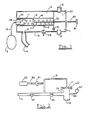
- the preferred embodiment of the invention is a device comprising three chambers, namely a plenum chamber 1, a desirably transparent pressure chamber 4 communicating with the plenum chamber via a main inflow valve 5, and a transparent cylindrical chamber 6 within the pressure chamber, communicating with the pressure chamber via holes 7 in the cylinder wall. There are many such holes 7 positioned around and along the cylinder wall.
- the chamber 6 may be formed from stainless steel mesh.
- the plenum chamber 1 receives ambient air or oxygen enriched gas via a connection 2. The gas flows through the plenum chamber 1 and out an outlet 3.
- Outlet 3 desirably has a one-way check valve so that gases cannot return through it.
- the bottom of the plenum chamber is provided with small condensate drain holes 29 to drain any moisture which condenses from the gas entering the plenum chamber.
- An outflow tube 14 leads from an outlet 13 in the wall of the pressure chamber 4 to a patient connector, as will be described in greater detail below.
- connection 2 is a standard fitting to which the output from a gas source which includes a heater/nebulizer may be connected, so that heated and humidified gas can be supplied to the patient.
- a gas source which includes a heater/nebulizer may be connected
- no such standard fitting is usually supplied, so that it is not possible to heat and humidify the gas'being supplied.
- oxygen enriched gas this of course means that the patient is receiving relatively cold and very dry gas. Since the time on manual resuscitation is limited, this may not be a significant problem in the case of adults. However, in the case of infants, the airway and lung passages, which are very small, can be dried out very quickly, and it would be much better to supply heated and humidified gas even for only very short time periods.
- the cylindrical chamber 6 houses an adjustable platform 8, resembling a piston, for adjusting the volume of the chamber 6.
- a threaded volume adjustment rod 30 terminating in a knob 3 1 passes through a threaded opening 32 in the wall of the pressure chamber 4 at its inner.
- a wax seal or other suitable means (not shown), such as a fairly long threaded portion in the threaded opening 32, should be used to prevent leakage through the threads.
- Graduations 12 on the wall of the cylindrical chamber enable the operator to adjust the platform 8 to a position which will ensure that a desired volume of gas will be delivered towards the patient's lungs, by turning the adjustment knob 31 to position the platform 8 as desired.
- a balloon, bellows, piston, or rolling diaphragm (aballoon 11 is illustrated) is attached to the inside of the cylindrical chamber 6, and is sealed against the wall of the cylindrical chamber 6 by the operation of a plug 36 and O-ring 37 between the plug and wall which retains the balloon 11 in position.
- the balloon 11 is connected via a tube 10 to a bulb 9 which lies outside the device.
- the gas in the balloon-bulb circuit does not come into contact with the gas which circulates in the cylindrical and pressure chambers.
- An adjustable pop-off valve 28 is provided on the wall 16 of the pressure chamber 4 as a safety device for venting to ambient in the event that the pressure chamber 4 is accidentally overpressured, for example if an inappropriately large volume has been selected.
- This valve is a conventional spring-on-disk type of valve, the spring tension being adjustable by screw means (not shown).
- a minimum dead space Puritan Bennett valve 22 modified to function as a so-called Fink valve (the Fink modification of a Stephen-Slater valve) is installed in the outflow tube 14 near the distal end.
- the modification is effected by running a valve actuation tube 15 from the top of the Puritan Bennett valve 22 down to the outflow tube 14.
- the Puritan Bennett valve is modified to function as a Fink valve, instead of using the Fink modification of a Stephen-Slater valve, because it is considerably lighter in weight and because it has considerably less dead space.
- the valve actuation tube 15 has an inner diameter much smaller than that of the outflow tube 14, and terminates at the top of the modified Puritan Bennett valve in that valve's "collector valve" 17, which in the case of the Puritan Bennett valve is in the form of a balloon inflatable against a seat 23.
- the outflow tube 14 ends in a mask or endotracheal tube connector 18 (hereinafter referred to as the patient connector), which it placed onto the airway of the patient by way of a mask or endotracheal tube (not shown).
- Exhalation ports 19 on the distal side of the modified Puritan Bennett valve 22 open to the outside air when the collector valve 17 is deflated, so that the patient can exhale. The exhalation ports are occluded by the collector valve 17 when it is inflated against its seat 23.
- a P.E.E.P. (Positive End Expiratory Pressure) accessory 20 may be connected to the valve actuation tube 15 via a check valve 21 which permits flow only in the direction from the PEEP accessory 20 to the valve actuation tube 15.
- a check valve 21 which permits flow only in the direction from the PEEP accessory 20 to the valve actuation tube 15.
- the check valve 21 prevents gas flowing down the valve actuation tube 15 during the inspiration cycle from being diverted from the collector valve 17 and flowing towards the PEEP accessory 20 when the PEEP option is not being used.
- the PEEP accessory 20 can be set so that the collector valve 17 is inflated to varying degrees, thus controlling the PEEP by allowing the gas to escape from the circuit and the patient's lungs only down to the desired PEEP level, representing an increase in functional residual capacity of the lungs. This is accomplished by varying the flow rate of the gas from the independent supply, and observing the PEEP shown on the pressure gauge 50 described below.
- a bleed hole 35 is provided close to the check valve 21 so that the constant flow to the one way valve doesn't completely close the exhalation port by overinflation of the collector valve 17, and to provide for more precise control of the PEEP since supply line pressure is much higher than the desired PEEP.
- Two check valves are provided in the outflow tube 14 in the region of the modified Puritan Bennett valve.
- One check valve 25 is positioned on the device side of the valve actuation tube 15, to improve the operation of the PEEP system by preventing flow from the PEEP system down the valve actuation tube and back the outflow tube 14.
- the second check valve 26 is positioned on the distal side of the valve actuation tube 15, to prevent exhaled breath from entering the system.
- a pressure tap 49 may be taken from the patient connector 18 downstream of the check valve 26, and is connected to a pressure gauge 50 to provide a reading of pressure there.
- the clinician In adjusting the position of the platform 8, the clinician must take into account the anticipated compressible volume loss, which is determined by the so-called compliance factor of the overall device.
- the anticipated compressible volume loss which is determined by the so-called compliance factor of the overall device.
- a slightly larger volume of gas must be displaced by the balloon 11, taking into account the compressible volume loss.
- the volume of the whole apparatus including pressure chamber 4 and the outflow tube 14 leading to the patient should be kept as small as practically possible.
- the volume of gas to be introduced into the lungs is selected, allowing for the anticipated compressible volume loss, by adjusting the position of the platform 8 in the cylindrical chamber 6 by means of the adjustment knob 31.
- the bulb 9 is squeezed by hand.
- the bulb 9 When the bulb 9 is compressed the balloon 11 inflates to fill the selected volume of the cylindrical chamber 6, displacing the gas in the cylindrical chamber into the pressure chamber 4 through the holes 7.
- Many holes 7 are provided, so that the inflating balloon cannot occlude all of them to prematurely block further displacement of gas; also, as is obvious, the balloon 11 and bulb 9 must be large enough to be able to fils, the cylindrical chamber 6 at its maximum volume setting).
- the increase in gas pressure in the pressure chamber 4 resulting from the displacement closes the main air in-flow valve 5.
- a volume of gas corresponding to the displaced volume, i.e. the adjusted volume of the cylindrical chamber 6, is forced into the outflow tube 14 which leads to the patient.
- the volume delivered corresponds to the volume displaced in accordance with
- Gas flowing down the outflow tube 14 splits at the junction of the outflow tube with the valve actuation tube 15. Gas in the valve actuation tube 15 inflates the collector valve 17 occluding the exhalation ports 19. The only pathway for the pressurized gas in the outflow tube 14 is into the patient's lungs through the patient connector 18.
- the operator When the operator ceases to compress the bulb 9, it actively draws back the volume of air used to inflate the balloon 11, due to the bulb's reshaping properties.
- the balloon 1 1 in the cylindrical chamber 6 deflates, thus reducing pressure in the cylindrical chamber 6 and pressure chamber 4.
- the main in- flow valve 5 reopens, allowing gas to flow into the pressure chamber 4 from the plenum chamber 1.
- the collector valve 17 With no positive pressure and flow maintained in the outflow tube 14, the collector valve 17 deflates through the valve actuation tube 15 and out through the exhalation ports 19, which thus open to permit gas to escape from the patient's lungs.
- cylindrical chamber 6 be positioned within the pressure chamber 4, as long as there is some connection between the two which permits gas to be displaced from the cylindrical chamber into the pressure chamber. It should also be appreciated that the "cylindrical" chamber 6 need not in fact be cylindrical; in the preferred embodiment, a cylindrical shape has been selected for convenience, but that shape is by no means essential.
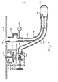
- FIG. 3 A modification of the embodiment of Figures 1 and 2 is shown in Figure 3.
- substantially all of the apparatus of Figure 2 is secured to and forms part of the wall 16 of the chamber 4.
- a cylindrical extension 110 Integral with or secured to the wall 16 is a cylindrical extension 110, threaded on its outside at 111, to which there is threaded a housing 112, which will be described in detail below. Also extending through the wall 16 of the chamber 4 is a gas outlet 113 corresponding to the outlet 13 of Figure 1.
- the housing is internally threaded at 115 to mate with the threads 111 on the cylindrical extension 112. It contains the P.E.E.P valve, as shown.
- gas can flow to the exhalation balloon 117 which, on expansion, can obturate an opening 120 defining a valve seat.
- An adjustable, spring loaded valve 121 is provided downstream of the opening 120. Regulation of the valve 121 by rotation of the knurled handle varies the pressure of the valve element 121 against the seat 122.
- a conduit to which there may be attached a manometer 150, and which has a release valve, or pop-off valve 123 which will release gases in the event of inadvertant overpressure.
- a patient circuit Downstream of the valve 123 and downstream of the outlet there is connected a patient circuit, which may be a unitary disposable element formed from a suitable thermoplastic comprising a dual conduit formed into a Y at its proximal end for connection to the outlet 129 of the PEEP valve and extension 130 downstream of valve 123.
- the connector includes an outflow or gas supply branch 124 having a one-way valve 126 and a return branch 127.
- a typical patient connector 128, is provided to which there may be attached a mask or endotracheal tube (not shown).
Landscapes
- Health & Medical Sciences (AREA)
- Emergency Medicine (AREA)
- Hematology (AREA)
- Life Sciences & Earth Sciences (AREA)
- Engineering & Computer Science (AREA)
- Anesthesiology (AREA)
- Biomedical Technology (AREA)
- Heart & Thoracic Surgery (AREA)
- Veterinary Medicine (AREA)
- Pulmonology (AREA)
- Animal Behavior & Ethology (AREA)
- General Health & Medical Sciences (AREA)
- Public Health (AREA)
- Critical Care (AREA)
- Percussion Or Vibration Massage (AREA)
- Accommodation For Nursing Or Treatment Tables (AREA)
Applications Claiming Priority (2)
| Application Number | Priority Date | Filing Date | Title |
|---|---|---|---|
| CA000510134A CA1247975A (en) | 1986-05-27 | 1986-05-27 | Volume-controlled manual resuscitator |
| CA510134 | 1986-05-27 |
Publications (2)
| Publication Number | Publication Date |
|---|---|
| EP0247859A2 true EP0247859A2 (de) | 1987-12-02 |
| EP0247859A3 EP0247859A3 (de) | 1988-09-07 |
Family
ID=4133223
Family Applications (1)
| Application Number | Title | Priority Date | Filing Date |
|---|---|---|---|
| EP87304702A Withdrawn EP0247859A3 (de) | 1986-05-27 | 1987-05-27 | Manuelles Wiederbelebungsgerät mit Volumenkontrolle |
Country Status (3)
| Country | Link |
|---|---|
| US (1) | US4782831A (de) |
| EP (1) | EP0247859A3 (de) |
| CA (1) | CA1247975A (de) |
Families Citing this family (15)
| Publication number | Priority date | Publication date | Assignee | Title |
|---|---|---|---|---|
| DE3817091A1 (de) * | 1988-05-19 | 1989-11-30 | Draegerwerk Ag | Kolben-zylindereinheit als foerdervorrichtung in einem beatmungsgeraet |
| US4898165A (en) * | 1988-12-08 | 1990-02-06 | Lyle Warzeka | Breathing apparatus |
| US5628305A (en) * | 1995-09-27 | 1997-05-13 | Richard J. Melker | Universal ventilation device |
| DK44999A (da) | 1998-03-31 | 1999-10-01 | Ambu Int As | Indretning til udførelse af kunstigt åndedræt på en patient |
| US5944013A (en) * | 1998-12-11 | 1999-08-31 | Burch; John M. | Resuscitator |
| US7121278B2 (en) | 2001-01-23 | 2006-10-17 | Michael David Maguire | Method and apparatus for manual delivery of volume and pressure-control artificial ventilation |
| WO2007009063A2 (en) | 2005-07-13 | 2007-01-18 | Branch Thomas P | Apparatus and method for evaluating ligaments |
| US20100307603A1 (en) * | 2009-06-03 | 2010-12-09 | The Marketing Store Worldwide, LP | Gas Pump with Limiting Pressure Feature |
| US9289157B2 (en) | 2010-08-13 | 2016-03-22 | ERML Inc. | Robotic knee testing device, subjective patient input device and methods for using same |
| US9408771B2 (en) | 2010-08-27 | 2016-08-09 | Ermi, Inc. | Bladder driven linear cylinder and associated devices driven thereby |
| US9999742B2 (en) * | 2012-04-10 | 2018-06-19 | Fisher & Paykel Healthcare Limited | Combination CPAP and resuscitation systems and methods |
| US9814411B2 (en) | 2012-09-17 | 2017-11-14 | Emri, Inc. | Robotic knee testing (RKT) device having decoupled drive capability and systems and methods providing the same |
| US12138389B2 (en) | 2020-03-10 | 2024-11-12 | Jonathon D. Rowe | Manual resuscitator, ventilation control assembly, and method of use |
| US12076293B2 (en) | 2020-07-10 | 2024-09-03 | Sergey Shushunov | Cardiopulmonary resuscitation (CPR) using chest compressions synchronised with alternating pressure mechanical ventilation |
| PE20220845A1 (es) * | 2020-10-23 | 2022-05-24 | Pontificia Univ Catolica Del Peru | Ventilador manual volumetrico |
Family Cites Families (14)
| Publication number | Priority date | Publication date | Assignee | Title |
|---|---|---|---|---|
| CA782326A (en) * | 1968-04-09 | E. W. Manley Roger | Respiratory metering device | |
| US2711170A (en) * | 1954-03-18 | 1955-06-21 | Alfred B Bornstein | Oxygen breathing apparatus |
| US3090380A (en) * | 1961-04-13 | 1963-05-21 | John F Dold | Resuscitation device |
| GB1169203A (en) * | 1966-06-30 | 1969-10-29 | Cape Engineering Company Ltd | Device for Administering a Gas to a Patient |
| US3548821A (en) * | 1967-08-23 | 1970-12-22 | Vladmir Spiridonovich Gigauri | Apparatus for artificial ventilation of lungs |
| GB1328087A (en) * | 1969-09-15 | 1973-08-30 | Pye Ltd | Pneumatically controlled medical respirators |
| GB1374581A (en) * | 1970-10-17 | 1974-11-20 | Cape Eng Co Ltd | Apparatus for administering gas to a patient |
| IT1001622B (it) * | 1973-11-05 | 1976-04-30 | Malleni R | Sistema e dispositivo perfezionato per respirazione artificiale in particolare nel campo pediatrico |
| US3933171A (en) * | 1974-04-09 | 1976-01-20 | Airco, Inc. | Anesthesia breathing circuit with positive end expiratory pressure valve |
| GB1592548A (en) * | 1977-09-30 | 1981-07-08 | Nat Res Dev | Medical ventilation apparatus |
| US4245633A (en) * | 1979-01-31 | 1981-01-20 | Erceg Graham W | PEEP providing circuit for anesthesia systems |
| US4351329A (en) * | 1980-11-06 | 1982-09-28 | Bear Medical Systems, Inc. | High frequency breath pump |
| GB2095121A (en) * | 1981-03-20 | 1982-09-29 | Miller Donald Munro | Anaesthesia apparatus having manual or automatic ventilation |
| DE3229240C2 (de) * | 1982-08-05 | 1986-09-18 | Interspiro GmbH, 7529 Forst | Für Überdruckbetrieb geeignetes Atemschutzgerät |
-
1986
- 1986-05-27 CA CA000510134A patent/CA1247975A/en not_active Expired
-
1987
- 1987-05-27 EP EP87304702A patent/EP0247859A3/de not_active Withdrawn
- 1987-05-27 US US07/054,707 patent/US4782831A/en not_active Expired - Fee Related
Also Published As
| Publication number | Publication date |
|---|---|
| US4782831A (en) | 1988-11-08 |
| CA1247975A (en) | 1989-01-03 |
| EP0247859A3 (de) | 1988-09-07 |
Similar Documents
| Publication | Publication Date | Title |
|---|---|---|
| US5678540A (en) | Breathing gas system | |
| US4782831A (en) | Volume-controlled manual resuscitator | |
| US3467092A (en) | Anesthesia apparatus and resuscitator | |
| US5487383A (en) | Tracheal tube cuff inflation control and monitoring system | |
| US4020834A (en) | Respirator and method | |
| US4060078A (en) | Ventilator and method | |
| US6412483B1 (en) | Oxygen blending in a piston ventilator | |
| US4471775A (en) | Endotracheal tube cuff synchronizing system | |
| US5862802A (en) | Ventilator having an oscillatory inspiratory phase and method | |
| US5497767A (en) | Method and apparatus for supplying fresh gas to a patient during manual ventilation | |
| US3933171A (en) | Anesthesia breathing circuit with positive end expiratory pressure valve | |
| US4456008A (en) | Respiratory apparatus and method | |
| US5007420A (en) | Ventilator having an oscillatory inspiratory phase and method | |
| US5116088A (en) | Ventilator having an oscillatory inspiratory phase and method | |
| US4924862A (en) | Pressure controller and leak detector for tracheal tube cuff | |
| US3529596A (en) | Automatic intermittent tracheotomy tube cuff inflator-deflator | |
| US4991576A (en) | Anesthesia rebreathing system | |
| US4164219A (en) | Ventilator | |
| US5507280A (en) | Anesthesia rebreathing system | |
| EP1795222A1 (de) | Narkosebeatmungssystem mit manueller Beatmung | |
| CN214807554U (zh) | 呼吸治疗系统和呼吸治疗设备以及连接器元件 | |
| US6102041A (en) | Respiratory assistance device | |
| JP3615238B2 (ja) | 患者用人工呼吸器の呼吸回路の気道圧力を呼吸の吸息サイクル中に制御するシステム | |
| EP4135813B1 (de) | Vorrichtung und system zur atemunterstützung | |
| EP4135814B1 (de) | Vorrichtung und system zur atemunterstützung |
Legal Events
| Date | Code | Title | Description |
|---|---|---|---|
| PUAI | Public reference made under article 153(3) epc to a published international application that has entered the european phase |
Free format text: ORIGINAL CODE: 0009012 |
|
| AK | Designated contracting states |
Kind code of ref document: A2 Designated state(s): AT BE CH DE FR GB IT LI NL SE |
|
| PUAL | Search report despatched |
Free format text: ORIGINAL CODE: 0009013 |
|
| AK | Designated contracting states |
Kind code of ref document: A3 Designated state(s): AT BE CH DE FR GB IT LI NL SE |
|
| 17P | Request for examination filed |
Effective date: 19890306 |
|
| STAA | Information on the status of an ep patent application or granted ep patent |
Free format text: STATUS: THE APPLICATION IS DEEMED TO BE WITHDRAWN |
|
| 18D | Application deemed to be withdrawn |
Effective date: 19901201 |