EP0247698B1 - Trailer - Google Patents
Trailer Download PDFInfo
- Publication number
- EP0247698B1 EP0247698B1 EP19870200983 EP87200983A EP0247698B1 EP 0247698 B1 EP0247698 B1 EP 0247698B1 EP 19870200983 EP19870200983 EP 19870200983 EP 87200983 A EP87200983 A EP 87200983A EP 0247698 B1 EP0247698 B1 EP 0247698B1
- Authority
- EP
- European Patent Office
- Prior art keywords
- trailer
- rear wall
- wall part
- wheel set
- chassis
- Prior art date
- Legal status (The legal status is an assumption and is not a legal conclusion. Google has not performed a legal analysis and makes no representation as to the accuracy of the status listed.)
- Expired
Links
Images

Classifications
-
- B—PERFORMING OPERATIONS; TRANSPORTING
- B60—VEHICLES IN GENERAL
- B60P—VEHICLES ADAPTED FOR LOAD TRANSPORTATION OR TO TRANSPORT, TO CARRY, OR TO COMPRISE SPECIAL LOADS OR OBJECTS
- B60P3/00—Vehicles adapted to transport, to carry or to comprise special loads or objects
- B60P3/32—Vehicles adapted to transport, to carry or to comprise special loads or objects comprising living accommodation for people, e.g. caravans, camping, or like vehicles
- B60P3/34—Vehicles adapted to transport, to carry or to comprise special loads or objects comprising living accommodation for people, e.g. caravans, camping, or like vehicles the living accommodation being expansible, collapsible or capable of rearrangement
Definitions
- the invention relates to a trailer for providing residential or temporary accommodation, such as a caravan, consisting substantially of a roof part in addition to a front and rear wall part and at least one wheel set with tow-bar bearing these parts.
- the invention relates particularly to a folding trailer.
- Folding trailers according to the preamble of claim 1 are known in many forms (see for example FR-A-1 001 152 and FR-A-1 525 699), the object being to considerably decrease the air resistance during travel and to improve the maneuvrability of the train consisting of the pulled and pulling vehicle.
- many of these trailers are comparatively simple and can be set up in a short time, there are however a number of drawbacks attached to them. Setting up has to be carried out with some proficiency, which not everyone possesses.
- the trailers are moreover often formed with tent-cloth or canvas, which does not contribute to the durability of such trailers.
- the invention has for its object to obviate the above stated drawbacks and provides for this purpose a trailer of the type described in the preamble which is distinguished in that the roof part and rear wall part and the roof part and front wall part are connected to each other for pivoting on a horizontal axis.
- the side walls and base can take a random form, but according to the invention it is recommended that the longitudinal walls be manufactured of one or more removable panels between front and rear wall parts and roof part. These panels can be stored away in the three previously mentioned pivoting parts before folding up.
- the same embodiment relates to the floor, which according to the invention can also consist of removable panels.
- At least the rear wall part has a lockable wheel set, which on the one hand serves to support the trailer during transport of same and on the other serves as a temporary support when the trailer is folded out, by locking this wheel set against rotation.
- the tow-bar be connected for pivoting to the front wall part, whereby the tow-bar is provided at the pivoting end with a second wheel set.
- This second wheel set can take the form of a pair of support rollers which only have a supporting function when folding out takes place.
- the second wheel set can form a tandem axle together with the first wheel set.
- the trailer is provided with a fixed chassis with tow-bar, on which the front and rear wall parts are mounted for sliding.
- the wheels do not have to be directly coupled to the front and rear wall parts, but can be attached directly to the chassis as, for example, a tandem axle.
- Sliding of the front and rear wall parts is performed preferably by means of a guiding on the chassis by a cylinder. Actuation of the cylinder can be carried out in any random manner.
- the roof, rear and/or front wall parts be given a box or tray-like form.
- a box or tray-like form offers the advantage that a cupboard or kitchen lay-out can already be permanently arranged in the box. This also achieves the advantage that the total length of the trailer after folding out is increased considerably, since the depth of the front and rear wall parts is added to the roof length, which results in a much greater space than in known folding trailers.
- the roof part Indicated in the drawing with the numeral 1 is the roof part, with 2 the front wall part and with 3 the rear wall part of the trailer. The whole is carried by a wheel set 4.
- the trailer is towed by means of a tow-bar 5 which is connected in known manner to the towing ball 6 of a tractive vehicle (not shown).
- the front and rear wall parts 2, 3 are connected to the roof part 1 at the pivot axes A and B respectively.
- the pivot axes run horizontally and lie close to the front and rear edges of roof part 1.
- Each part can take a box or tray-like form and is provided for this purpose in the embodiment shown with a window-like beam frame 7, 8 and 9 which is covered on the side facing the outside with a covering of random material. In this way is created a closed trailer, which contributes to a small air resistance.
- the tow-bar 5 is preferably connected at C to the frame part 7 for pivoting on an axis parallel to that of A and B, see also fig. 4.
- the tow-bar 5 is formed for this purpose at the rear end with a cross beam 10 connected firmly to it, which beam is provided at both ends with axle journals 11. These axle journals 11 are mounted in random manner in the beam frame 7 of the front wall part 2.
- a pair of support rollers 12 Arranged on the under-side of cross beam 10 are a pair of support rollers 12, which are mounted for free rotation in arms 13 connected firmly to beam 10.
- the front wall part 2 will drop downward on the pivot axis A until support wheel 12 reaches the ground, see fig. 2.
- the tractive vehicle can then move forward in the direction of the arrow P1 in fig. 2, which results in an upward movement of the front wall part, which tilts further underneath axis A.
- the roof part 1 is hereby moved upward, whereby the rear pivot axis B also moves upward because the rear wall part 3 will tilt round wheel set 4 in clockwise direction. This movement can be continued until the position as in fig. 3 has been reached.
- the user can if necessary place separate supports 17 under the front and rear wall parts, these supports being folded downward at the correct moment relative to beam frames 8, 9.
- the now open side walls and base of the trailer can be closed in random manner, for example by means of tent-cloth and the like.
- Each front and rear wall part contains a double hinged panel 14 which is also connected for pivoting to the associated box-like front and rear wall parts.
- a floor panel 15 can in this way also be formed for pivoting with the associated front and rear wall parts.
- the side wall panels can also be accommodated in the roof part.
- These panels can be formed in the normal way with windows for the necessary incidence of light. These windows can also be situated in the bottom of the box-like front and rear wall parts.
- the latter can be pre-formed with cabinets, a bathroom/toilet area, kitchen and the like, whereby the roof part can like-wise be provided with storage apace.
- Folding in of the trailer into the travel position as in fig. 1 is performed in reverse sequence. This can be carried out by performing a movement with the tractive vehicle in the opposite direction of arrow P1 as in fig. 2, as a result of which the trailer automatically folds up.
- tow-bar 5 which at the start was located in a horizontal position, can be raised upward in the folded out position as according to arrow P2 in fig. 3 and can be locked at 16 in fig. 6.
- the fig 7-10 show another embodiment which is provided with a fixed chassis 20 consisting of two longitudinal beams 21 and a number of transverse beams 22 arranged at the correct positions.
- the form of the chassis can be of a random type.
- a tow-frame 23 Arranged at the front is a tow-frame 23 provided with a tow-bar 24 which can be attached in the usual manner to a tractive vehicle.
- the chassis is provided with swing-out supports 25 which are assumed to be per se known.
- chassis is formed with a double wheel set or tandem axle, whereby each wheel set is suspended spring-mounted relative to chassis 20 via a torsion shaft 26.
- the chassis is formed with a guide 27, which also serves as support rail for a travelling wheel 28, which will be further explained below.
- Travelling wheel 28 extends through the guide with an arm 29, to which is coupled the cylinder rod of a cylinder 30.
- the cylinder 30 supports on the frame 23 on the front of the chassis.
- a second guide 27′ is mounted in a similar manner, but on the front part of the chassis, whereby a cylinder (30′ but not shown), grips onto the associated arm of the roller 28′.
- This cylinder supports on the rear transverse beam of the chassis.
- the front and rear wall parts which here take the form of a box-like part 3, are each formed at a lower edge 31 of the box with the respective guide wheels 28 and 28′.
- the guide wheel 28 will roll along the top of guide 27 from the position as in fig. 7 to the position in fig. 8, which is effected in the embodiment being described by actuating the respective cylinders 30 and 30′.
- These press the roller 28 by means of the lever 29 in the required direction, as a result of which the front and rear panels fold out, this movement corresponding with the movement as according to the fig. 1-3.
- wheel 28 has to be displaced rearward over a distance that is greater than the length of the guide track 27, see fig. 10 inter alia.
- This elongation can be effected by incorporating a telescopic part 32 in guide 27. As soon as the roller set 28 reaches the end of track 27 this part 32 will also be moved, together with the roller set 28, out of the guide 27 by the cylinder 30.
- the sliding movement can be improved by forming the end of part 32 with a transverse beam 33 which is provided at both ends with a telescopic sliding part 34.
- Roller set 28′ which rolls over the track 27′ has a similar construction, so that each roller 28, 28′ can be carried far outside the normal length of the chassis, which enlarges the total accommodation length relative to the transport length of the trailer.
- the side panels in the embodiment as according to fig. 7 and 8 can be fitted in a manner corresponding to that shown in fig. 5. It is however also possible to swivel the side panels downward from the roof part, this being assumed in fig. 8.
- box-like front and rear wall parts can have any random shape, in order to accommodate exceptional forms of guiding or required lay-out of the caravan as according to fig. 7 and 8.
- the invention is not limited to the above described embodiment. It is thus possible to replace the pair of rollers 12 with a wheel set the same as that (4) of the rear wall part 3. In this way a kind of tandem axle trailer is obtained, which is very suitable for large embodiments. In its folded out position the trailer does not have to be arranged stationary, but, depending on the positioning and size of the wheel sets, a mobile embodiment can also be obtained. The enlarged trailer can then be used for transport. In this embodiment, the front wheel set of the tow-bar can be mounted for pivoting on a vertical shaft in order to enable steering.
- the box-like parts shown can also be made as double-walled, foam filled, self-supporting bodywork elements, whereby the beam system as in fig. 4 becomes superfluous.
Description
- The invention relates to a trailer for providing residential or temporary accommodation, such as a caravan, consisting substantially of a roof part in addition to a front and rear wall part and at least one wheel set with tow-bar bearing these parts. The invention relates particularly to a folding trailer.
- Folding trailers according to the preamble of
claim 1 are known in many forms (see for example FR-A-1 001 152 and FR-A-1 525 699), the object being to considerably decrease the air resistance during travel and to improve the maneuvrability of the train consisting of the pulled and pulling vehicle. Although many of these trailers are comparatively simple and can be set up in a short time, there are however a number of drawbacks attached to them. Setting up has to be carried out with some proficiency, which not everyone possesses. The trailers are moreover often formed with tent-cloth or canvas, which does not contribute to the durability of such trailers. - The invention has for its object to obviate the above stated drawbacks and provides for this purpose a trailer of the type described in the preamble which is distinguished in that the roof part and rear wall part and the roof part and front wall part are connected to each other for pivoting on a horizontal axis.
- As a result of this location of the pivoting axes it is possible to fold the front and rear wall parts beneath the roof part, which considerably lowers the height of the trailer, thereby ensuring its maneuvrability. Folding out of the trailer can be carried out by applying a force to the front wall part with the tractive vehicle while restraining the rear wall part, so that the trailer folds out automatically and finishes up in the user position. All further manual operations are then superfluous.
- The side walls and base can take a random form, but according to the invention it is recommended that the longitudinal walls be manufactured of one or more removable panels between front and rear wall parts and roof part. These panels can be stored away in the three previously mentioned pivoting parts before folding up.
- The same embodiment relates to the floor, which according to the invention can also consist of removable panels.
- In one embodiment at least the rear wall part has a lockable wheel set, which on the one hand serves to support the trailer during transport of same and on the other serves as a temporary support when the trailer is folded out, by locking this wheel set against rotation.
- It is also recommended according to the invention that the tow-bar be connected for pivoting to the front wall part, whereby the tow-bar is provided at the pivoting end with a second wheel set.
- This second wheel set can take the form of a pair of support rollers which only have a supporting function when folding out takes place.
- Alternatively the second wheel set can form a tandem axle together with the first wheel set.
- In another embodiment the trailer is provided with a fixed chassis with tow-bar, on which the front and rear wall parts are mounted for sliding. In this embodiment the wheels do not have to be directly coupled to the front and rear wall parts, but can be attached directly to the chassis as, for example, a tandem axle.
- Sliding of the front and rear wall parts is performed preferably by means of a guiding on the chassis by a cylinder. Actuation of the cylinder can be carried out in any random manner.
- Finally, it is recommended that the roof, rear and/or front wall parts be given a box or tray-like form. Such a box or tray-like form offers the advantage that a cupboard or kitchen lay-out can already be permanently arranged in the box. This also achieves the advantage that the total length of the trailer after folding out is increased considerably, since the depth of the front and rear wall parts is added to the roof length, which results in a much greater space than in known folding trailers.
- The invention is further elucidated in the figure description of an embodiment following below.
- In the drawing:
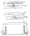
- Fig. 1 shows an upright side view with partly broken away portions of the trailer according to the invention, in the towed travel position,
- Fig. 2 shows a similar side view of the trailer from fig. 1, at the start of the folding out of same,
- Fig. 3 shows an upright side view of the folded out trailer from fig. 1,
- Fig. 4 is a perspective view of a detail of the support frame with tow-bar,
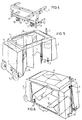
- Fig. 5 and 6 each show a perspective top view of the folded out trailer in the folded out position during fitting of side panels and base panels respectively,
- Fig. 7 and 8 each show a side view of a second embodiment in respectively folded and unfolded state,
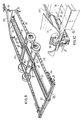
- Fig. 9 is a perspective top view of the chassis employed in the embodiment shown in fig. 7 and 8,
- Fig. 10 shows a detail of the guide from the chassis in fig. 9.
- Indicated in the drawing with the
numeral 1 is the roof part, with 2 the front wall part and with 3 the rear wall part of the trailer. The whole is carried by awheel set 4. The trailer is towed by means of a tow-bar 5 which is connected in known manner to the towing ball 6 of a tractive vehicle (not shown). - The front and
rear wall parts roof part 1 at the pivot axes A and B respectively. The pivot axes run horizontally and lie close to the front and rear edges ofroof part 1. - Each part can take a box or tray-like form and is provided for this purpose in the embodiment shown with a window-like beam frame 7, 8 and 9 which is covered on the side facing the outside with a covering of random material. In this way is created a closed trailer, which contributes to a small air resistance.
- The tow-
bar 5 is preferably connected at C to the frame part 7 for pivoting on an axis parallel to that of A and B, see also fig. 4. The tow-bar 5 is formed for this purpose at the rear end with across beam 10 connected firmly to it, which beam is provided at both ends withaxle journals 11. Theseaxle journals 11 are mounted in random manner in the beam frame 7 of thefront wall part 2. Arranged on the under-side ofcross beam 10 are a pair ofsupport rollers 12, which are mounted for free rotation inarms 13 connected firmly tobeam 10. - Folding out of the trailer from fig. 1 is carried out as follows.
- As a result of blocking the wheel set 4 by random means (not shown) and releasing locks (not shown) fitted between the parts, the
front wall part 2 will drop downward on the pivot axis A untilsupport wheel 12 reaches the ground, see fig. 2. The tractive vehicle can then move forward in the direction of the arrow P₁ in fig. 2, which results in an upward movement of the front wall part, which tilts further underneath axis A. Theroof part 1 is hereby moved upward, whereby the rear pivot axis B also moves upward because therear wall part 3 will tilt round wheel set 4 in clockwise direction. This movement can be continued until the position as in fig. 3 has been reached. The user can if necessary placeseparate supports 17 under the front and rear wall parts, these supports being folded downward at the correct moment relative to beam frames 8, 9. - The now open side walls and base of the trailer can be closed in random manner, for example by means of tent-cloth and the like.
- It is however also possible to form the side wall from one or more removable panels. A possible embodiment is shown in the fig. 5 and 6. Each front and rear wall part contains a double hinged
panel 14 which is also connected for pivoting to the associated box-like front and rear wall parts. Afloor panel 15 can in this way also be formed for pivoting with the associated front and rear wall parts. - If required the side wall panels can also be accommodated in the roof part.
- These panels can be formed in the normal way with windows for the necessary incidence of light. These windows can also be situated in the bottom of the box-like front and rear wall parts.
- Owing to the box form of the front and rear wall parts, the latter can be pre-formed with cabinets, a bathroom/toilet area, kitchen and the like, whereby the roof part can like-wise be provided with storage apace.
- Folding in of the trailer into the travel position as in fig. 1 is performed in reverse sequence. This can be carried out by performing a movement with the tractive vehicle in the opposite direction of arrow P₁ as in fig. 2, as a result of which the trailer automatically folds up.
- It is finally noted that the tow-
bar 5, which at the start was located in a horizontal position, can be raised upward in the folded out position as according to arrow P₂ in fig. 3 and can be locked at 16 in fig. 6. - The fig 7-10 show another embodiment which is provided with a
fixed chassis 20 consisting of two longitudinal beams 21 and a number oftransverse beams 22 arranged at the correct positions. The form of the chassis can be of a random type. - Arranged at the front is a tow-
frame 23 provided with a tow-bar 24 which can be attached in the usual manner to a tractive vehicle. The chassis is provided with swing-outsupports 25 which are assumed to be per se known. - In addition the chassis is formed with a double wheel set or tandem axle, whereby each wheel set is suspended spring-mounted relative to
chassis 20 via atorsion shaft 26. - A particular feature according to the invention is that the chassis is formed with a
guide 27, which also serves as support rail for a travellingwheel 28, which will be further explained below. Travellingwheel 28 extends through the guide with anarm 29, to which is coupled the cylinder rod of acylinder 30. Thecylinder 30 supports on theframe 23 on the front of the chassis. - A
second guide 27′ is mounted in a similar manner, but on the front part of the chassis, whereby a cylinder (30′ but not shown), grips onto the associated arm of theroller 28′. This cylinder supports on the rear transverse beam of the chassis. - It is presumed that the front and rear wall parts, which here take the form of a box-
like part 3, are each formed at alower edge 31 of the box with therespective guide wheels guide wheel 28 will roll along the top ofguide 27 from the position as in fig. 7 to the position in fig. 8, which is effected in the embodiment being described by actuating therespective cylinders roller 28 by means of thelever 29 in the required direction, as a result of which the front and rear panels fold out, this movement corresponding with the movement as according to the fig. 1-3. - In view of the box-like front and rear wall parts,
wheel 28 has to be displaced rearward over a distance that is greater than the length of theguide track 27, see fig. 10 inter alia. This elongation can be effected by incorporating atelescopic part 32 inguide 27. As soon as the roller set 28 reaches the end oftrack 27 thispart 32 will also be moved, together with the roller set 28, out of theguide 27 by thecylinder 30. - The sliding movement can be improved by forming the end of
part 32 with a transverse beam 33 which is provided at both ends with a telescopic slidingpart 34. - Roller set 28′ which rolls over the
track 27′ has a similar construction, so that eachroller - The side panels in the embodiment as according to fig. 7 and 8 can be fitted in a manner corresponding to that shown in fig. 5. It is however also possible to swivel the side panels downward from the roof part, this being assumed in fig. 8.
- It will be apparent that the form of the box-like front and rear wall parts can have any random shape, in order to accommodate exceptional forms of guiding or required lay-out of the caravan as according to fig. 7 and 8.
- It will be apparent that more than one cylinder can be fitted, which can then be placed parallel next to one another or in series behind one another.
- The invention is not limited to the above described embodiment. It is thus possible to replace the pair of
rollers 12 with a wheel set the same as that (4) of therear wall part 3. In this way a kind of tandem axle trailer is obtained, which is very suitable for large embodiments. In its folded out position the trailer does not have to be arranged stationary, but, depending on the positioning and size of the wheel sets, a mobile embodiment can also be obtained. The enlarged trailer can then be used for transport. In this embodiment, the front wheel set of the tow-bar can be mounted for pivoting on a vertical shaft in order to enable steering. The box-like parts shown can also be made as double-walled, foam filled, self-supporting bodywork elements, whereby the beam system as in fig. 4 becomes superfluous.
Claims (11)
Priority Applications (1)
| Application Number | Priority Date | Filing Date | Title |
|---|---|---|---|
| AT87200983T ATE62876T1 (en) | 1986-05-26 | 1987-05-26 | FAN. |
Applications Claiming Priority (4)
| Application Number | Priority Date | Filing Date | Title |
|---|---|---|---|
| NL8601343 | 1986-05-26 | ||
| NL8601343A NL8601343A (en) | 1986-05-26 | 1986-05-26 | Trailer providing temporary, residential accommodation - has roof part and rear wall part connected to roof and front wall for pivoting on horizontal axis |
| NL8700090A NL8700090A (en) | 1986-05-26 | 1987-01-15 | DRAWN ROAD VEHICLE. |
| NL8700090 | 1987-01-15 |
Publications (2)
| Publication Number | Publication Date |
|---|---|
| EP0247698A1 EP0247698A1 (en) | 1987-12-02 |
| EP0247698B1 true EP0247698B1 (en) | 1991-04-24 |
Family
ID=26646133
Family Applications (1)
| Application Number | Title | Priority Date | Filing Date |
|---|---|---|---|
| EP19870200983 Expired EP0247698B1 (en) | 1986-05-26 | 1987-05-26 | Trailer |
Country Status (5)
| Country | Link |
|---|---|
| EP (1) | EP0247698B1 (en) |
| DE (1) | DE3769515D1 (en) |
| ES (1) | ES2021342B3 (en) |
| GR (1) | GR3001935T3 (en) |
| NL (1) | NL8700090A (en) |
Families Citing this family (1)
| Publication number | Priority date | Publication date | Assignee | Title |
|---|---|---|---|---|
| GR1009106B (en) * | 2016-05-24 | 2017-09-08 | Χρηστος Νικολαου Χασιωτης | Transportable house in luggage form |
Family Cites Families (4)
| Publication number | Priority date | Publication date | Assignee | Title |
|---|---|---|---|---|
| FR1001152A (en) * | 1949-12-10 | 1952-02-20 | Convertible and folding automobile camping trailer | |
| FR1214816A (en) * | 1956-07-05 | 1960-04-12 | Extendable caravan stationary | |
| FR1518911A (en) * | 1967-02-15 | 1968-03-29 | Camper trailer equipped with a new type of swivel boxes | |
| FR1525699A (en) * | 1967-06-02 | 1968-05-17 | Folding process for camping caravan |
-
1987
- 1987-01-15 NL NL8700090A patent/NL8700090A/en not_active Application Discontinuation
- 1987-05-26 DE DE8787200983T patent/DE3769515D1/en not_active Expired - Lifetime
- 1987-05-26 EP EP19870200983 patent/EP0247698B1/en not_active Expired
- 1987-05-26 ES ES87200983T patent/ES2021342B3/en not_active Expired - Lifetime
-
1991
- 1991-05-10 GR GR91400599T patent/GR3001935T3/en unknown
Also Published As
| Publication number | Publication date |
|---|---|
| GR3001935T3 (en) | 1992-11-23 |
| ES2021342B3 (en) | 1991-11-01 |
| EP0247698A1 (en) | 1987-12-02 |
| DE3769515D1 (en) | 1991-05-29 |
| NL8700090A (en) | 1987-12-16 |
Similar Documents
| Publication | Publication Date | Title |
|---|---|---|
| US4480851A (en) | Stowable trailer | |
| US3572809A (en) | Expansible mobile home and fittings therefore | |
| AU599157B2 (en) | Combination access box and bed liner for vehicles | |
| CA1061379A (en) | Collapsible camper | |
| US6033002A (en) | Collapsible material carrier and hidden storage system for vehicle beds | |
| US4795304A (en) | Pickup truck loading ramp | |
| US2837778A (en) | Folding trailers | |
| EP0497498B1 (en) | Improvements relating to trailers | |
| US5628541A (en) | Expandable coach having at least one expansion chamber | |
| US6244651B1 (en) | Pickup truck bed cap | |
| US20170240089A1 (en) | Mini-Camper Attachable to Vehicle Hitch Receiver | |
| US5822930A (en) | Collapsible transportable deck for a house trailer or mobile home | |
| US3445134A (en) | Collapsible camper | |
| US3703311A (en) | Tent camping trailer | |
| US4863212A (en) | Trailer | |
| US4188057A (en) | Retractable patio assembly for recreational vehicle | |
| EP2500245A2 (en) | Single track trailer | |
| EP0247698B1 (en) | Trailer | |
| US11420696B2 (en) | Vertically stowable trailer | |
| US7273245B2 (en) | Camper and trailer combination having collapsible canopy | |
| DE3231323A1 (en) | Shopping trolley for use in conjunction with motor vehicles | |
| US3697122A (en) | Camping trailers | |
| US3677600A (en) | Camper trailer | |
| US2233181A (en) | Automobile body | |
| US3168343A (en) | Folding mobile shelter |
Legal Events
| Date | Code | Title | Description |
|---|---|---|---|
| PUAI | Public reference made under article 153(3) epc to a published international application that has entered the european phase |
Free format text: ORIGINAL CODE: 0009012 |
|
| AK | Designated contracting states |
Kind code of ref document: A1 Designated state(s): AT BE CH DE ES FR GB GR IT LI LU NL SE |
|
| 17P | Request for examination filed |
Effective date: 19880511 |
|
| 17Q | First examination report despatched |
Effective date: 19900622 |
|
| ITF | It: translation for a ep patent filed |
Owner name: STUDIO INGG. FISCHETTI & WEBER |
|
| GRAA | (expected) grant |
Free format text: ORIGINAL CODE: 0009210 |
|
| AK | Designated contracting states |
Kind code of ref document: B1 Designated state(s): AT BE CH DE ES FR GB GR IT LI LU NL SE |
|
| REF | Corresponds to: |
Ref document number: 62876 Country of ref document: AT Date of ref document: 19910515 Kind code of ref document: T |
|
| ET | Fr: translation filed | ||
| REF | Corresponds to: |
Ref document number: 3769515 Country of ref document: DE Date of ref document: 19910529 |
|
| PGFP | Annual fee paid to national office [announced via postgrant information from national office to epo] |
Ref country code: NL Payment date: 19910531 Year of fee payment: 5 |
|
| PGFP | Annual fee paid to national office [announced via postgrant information from national office to epo] |
Ref country code: BE Payment date: 19910628 Year of fee payment: 5 |
|
| PGFP | Annual fee paid to national office [announced via postgrant information from national office to epo] |
Ref country code: GR Payment date: 19910701 Year of fee payment: 5 |
|
| PGFP | Annual fee paid to national office [announced via postgrant information from national office to epo] |
Ref country code: SE Payment date: 19910703 Year of fee payment: 5 |
|
| PGFP | Annual fee paid to national office [announced via postgrant information from national office to epo] |
Ref country code: FR Payment date: 19910708 Year of fee payment: 5 |
|
| PGFP | Annual fee paid to national office [announced via postgrant information from national office to epo] |
Ref country code: ES Payment date: 19910709 Year of fee payment: 5 |
|
| PGFP | Annual fee paid to national office [announced via postgrant information from national office to epo] |
Ref country code: AT Payment date: 19910712 Year of fee payment: 5 |
|
| PGFP | Annual fee paid to national office [announced via postgrant information from national office to epo] |
Ref country code: DE Payment date: 19910725 Year of fee payment: 5 |
|
| PGFP | Annual fee paid to national office [announced via postgrant information from national office to epo] |
Ref country code: GB Payment date: 19910909 Year of fee payment: 5 |
|
| PGFP | Annual fee paid to national office [announced via postgrant information from national office to epo] |
Ref country code: CH Payment date: 19910925 Year of fee payment: 5 |
|
| PGFP | Annual fee paid to national office [announced via postgrant information from national office to epo] |
Ref country code: LU Payment date: 19911004 Year of fee payment: 5 |
|
| PLBE | No opposition filed within time limit |
Free format text: ORIGINAL CODE: 0009261 |
|
| STAA | Information on the status of an ep patent application or granted ep patent |
Free format text: STATUS: NO OPPOSITION FILED WITHIN TIME LIMIT |
|
| EPTA | Lu: last paid annual fee | ||
| 26N | No opposition filed | ||
| PG25 | Lapsed in a contracting state [announced via postgrant information from national office to epo] |
Ref country code: LU Free format text: LAPSE BECAUSE OF NON-PAYMENT OF DUE FEES Effective date: 19920526 Ref country code: AT Effective date: 19920526 Ref country code: GB Effective date: 19920526 |
|
| PG25 | Lapsed in a contracting state [announced via postgrant information from national office to epo] |
Ref country code: ES Free format text: LAPSE BECAUSE OF NON-PAYMENT OF DUE FEES Effective date: 19920527 Ref country code: SE Effective date: 19920527 |
|
| PG25 | Lapsed in a contracting state [announced via postgrant information from national office to epo] |
Ref country code: BE Effective date: 19920531 Ref country code: LI Effective date: 19920531 Ref country code: CH Effective date: 19920531 |
|
| REG | Reference to a national code |
Ref country code: GR Ref legal event code: FG4A Free format text: 3001935 |
|
| BERE | Be: lapsed |
Owner name: JANSEN JOHANNES FRANCISCUS MARIA Effective date: 19920531 |
|
| PG25 | Lapsed in a contracting state [announced via postgrant information from national office to epo] |
Ref country code: GR Free format text: THE PATENT HAS BEEN ANNULLED BY A DECISION OF A NATIONAL AUTHORITY Effective date: 19921130 |
|
| PG25 | Lapsed in a contracting state [announced via postgrant information from national office to epo] |
Ref country code: NL Effective date: 19921201 |
|
| NLV4 | Nl: lapsed or anulled due to non-payment of the annual fee | ||
| GBPC | Gb: european patent ceased through non-payment of renewal fee |
Effective date: 19920526 |
|
| PG25 | Lapsed in a contracting state [announced via postgrant information from national office to epo] |
Ref country code: FR Effective date: 19930129 |
|
| REG | Reference to a national code |
Ref country code: CH Ref legal event code: PL |
|
| PG25 | Lapsed in a contracting state [announced via postgrant information from national office to epo] |
Ref country code: DE Effective date: 19930202 |
|
| REG | Reference to a national code |
Ref country code: FR Ref legal event code: ST |
|
| REG | Reference to a national code |
Ref country code: GR Ref legal event code: MM2A Free format text: 3001935 |
|
| EUG | Se: european patent has lapsed |
Ref document number: 87200983.2 Effective date: 19921204 |
|
| REG | Reference to a national code |
Ref country code: ES Ref legal event code: FD2A Effective date: 19990201 |
|
| PG25 | Lapsed in a contracting state [announced via postgrant information from national office to epo] |
Ref country code: IT Free format text: LAPSE BECAUSE OF NON-PAYMENT OF DUE FEES;WARNING: LAPSES OF ITALIAN PATENTS WITH EFFECTIVE DATE BEFORE 2007 MAY HAVE OCCURRED AT ANY TIME BEFORE 2007. THE CORRECT EFFECTIVE DATE MAY BE DIFFERENT FROM THE ONE RECORDED. Effective date: 20050526 |