EP0247570B1 - Lochplatte zum Verbinden passender Enden von Kabeln, Rohren und dergleichen, insbesondere für Motorfahrzeuge - Google Patents
Lochplatte zum Verbinden passender Enden von Kabeln, Rohren und dergleichen, insbesondere für Motorfahrzeuge Download PDFInfo
- Publication number
- EP0247570B1 EP0247570B1 EP87107618A EP87107618A EP0247570B1 EP 0247570 B1 EP0247570 B1 EP 0247570B1 EP 87107618 A EP87107618 A EP 87107618A EP 87107618 A EP87107618 A EP 87107618A EP 0247570 B1 EP0247570 B1 EP 0247570B1
- Authority
- EP
- European Patent Office
- Prior art keywords
- plate
- bores
- pipes
- end portions
- bore
- Prior art date
- Legal status (The legal status is an assumption and is not a legal conclusion. Google has not performed a legal analysis and makes no representation as to the accuracy of the status listed.)
- Expired - Lifetime
Links
- 230000000284 resting effect Effects 0.000 claims description 13
- 230000001154 acute effect Effects 0.000 claims description 11
- 101100494448 Caenorhabditis elegans cab-1 gene Proteins 0.000 description 2
- 230000004048 modification Effects 0.000 description 2
- 238000012986 modification Methods 0.000 description 2
- 238000012856 packing Methods 0.000 description 2
- 230000002093 peripheral effect Effects 0.000 description 2
- 230000003247 decreasing effect Effects 0.000 description 1
- 230000002452 interceptive effect Effects 0.000 description 1
- 230000000670 limiting effect Effects 0.000 description 1
- 238000004519 manufacturing process Methods 0.000 description 1
- 239000000463 material Substances 0.000 description 1
- 239000007769 metal material Substances 0.000 description 1
- 238000000465 moulding Methods 0.000 description 1
- 229920003023 plastic Polymers 0.000 description 1
- 239000004033 plastic Substances 0.000 description 1
- 230000002829 reductive effect Effects 0.000 description 1
- 238000007789 sealing Methods 0.000 description 1
Images
Classifications
-
- F—MECHANICAL ENGINEERING; LIGHTING; HEATING; WEAPONS; BLASTING
- F16—ENGINEERING ELEMENTS AND UNITS; GENERAL MEASURES FOR PRODUCING AND MAINTAINING EFFECTIVE FUNCTIONING OF MACHINES OR INSTALLATIONS; THERMAL INSULATION IN GENERAL
- F16L—PIPES; JOINTS OR FITTINGS FOR PIPES; SUPPORTS FOR PIPES, CABLES OR PROTECTIVE TUBING; MEANS FOR THERMAL INSULATION IN GENERAL
- F16L5/00—Devices for use where pipes, cables or protective tubing pass through walls or partitions
- F16L5/02—Sealing
-
- B—PERFORMING OPERATIONS; TRANSPORTING
- B62—LAND VEHICLES FOR TRAVELLING OTHERWISE THAN ON RAILS
- B62D—MOTOR VEHICLES; TRAILERS
- B62D21/00—Understructures, i.e. chassis frame on which a vehicle body may be mounted
- B62D21/17—Understructures, i.e. chassis frame on which a vehicle body may be mounted forming fluid or electrical conduit means or having other means to accommodate the transmission of a force or signal
-
- B—PERFORMING OPERATIONS; TRANSPORTING
- B62—LAND VEHICLES FOR TRAVELLING OTHERWISE THAN ON RAILS
- B62D—MOTOR VEHICLES; TRAILERS
- B62D25/00—Superstructure or monocoque structure sub-units; Parts or details thereof not otherwise provided for
- B62D25/08—Front or rear portions
- B62D25/14—Dashboards as superstructure sub-units
Definitions
- This invention relates to a perforated plate for connecting together corresponding ends of cables, pipes and the like, in particular for motor vehicles.
- the known plates are substantially all of the aforesaid type, they each have an individual structure designed to solve certain problems, but which on the other hand leads to certain drawbacks.
- a plate of known type the bores are disposed in parallel rows, each of which appears on the surface of a respective step provided on the plate such as to form an acute angle of predetermined value to the resting plane defined by a connection flange extending from the plate itself.
- Such a structure designed to connect together a large number of cables or pipes has the drawback, when assembled, that the end portions of said cables or pipes extend perpendicular to the plate surface into which said through bores open, consequently obstructing a peripheral zone adjacent to the plate when in use.
- the object of the present invention is to provide a perforated plate of such a structure as to allow a large number of cables or pipes to be connected together, but without said cables or pipes substantially obstructing zones adjacent to said plate when in use.
- a perforated plate for connecting corresponding ends of cables, pipes and the like, in particular for motor vehicles comprising a plurality of through bores arranged in at least one row and having respective axes lying in planes parallel to each other and perpendicular to a resting plane of said plate, each one of said through bores being located in correspondence with an associated axis perpendicular to said resting plane and complanar with the respective one of said axes, as to form therewith an acute angle of a predetermined value, and characterised in that the opposite end portions of each of said through bores are arranged to receive connection means for the respective end portions of said cables, pipes and the like, and in that respective axes of adajacent through bores form said acute angle on opposite sides of said associated perpendicular axis.
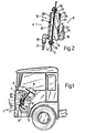
- the reference numeral 1 indicates overall an industrial vehicle cab showing in detail a front wall 2 and a dividing wall 3 which is interposed between the wall 2 and the driver's compartment of the cab 1, so as to define two respective chambers 4, 5.
- An instrument panel 6 is provided above the dividing wall 3, and a pedal 7 and steering wheel 8 can be seen on the side facing the interior of the chamber 5.
- the wall 3 comprises an aperture 9 which is engaged by a plate 10 constructed in accordance with the present invention. More particularly, the plate 10 has a flanged peripheral portion 11 which is fixed, at its resting surface 12, to a respective edge of the wall 3 by a pair of bolts 13.
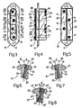
- the plate 10 comprises a plurality of through bores 14 each of which has its opposing ends suitably threaded, to be engaged when in use by respective L-shaped end connectors 18, 19 connected to respective pipes 21, 22 situated in the chambers 4 and 5 respectively.
- the plate 10 is of essentially T-shaped cross-section with a shank 24 and a pair of opposing appendices 25, 26 which are bounded, on the side facing the shank 24, by said surface 12.
- the through bores 14 have their respective axes 28 lying in planes which are parallel to each other and perpendicular to the resting plane defined by the surface 12.
- the reference numeral 30 indicates an axis perpendicular to the resting plane defined by the surface 12 and drawn in the plane in which the axis 28 of the respective bore 14 lies.
- each bore 14 does not coincide with said axis 30 but instead defines therewith a respective acute angle, indicated by A, such that adjacent through bores 14 open one in correspondence with a surface 31 of the appendix 25 and the other in correspondence with a surface 32 of the appendix 26 on the opposite side to the surface 12.
- the through bore 14 opens into a respective end surface 35, 36 of the shank 24.
- the surfaces 31 and 35 lie in parallel planes traversed perpendicularly by the axis 28 of the bore 14.
- the surfaces 32 and 36 lie in parallel planes also traversed in a perpendicular direction by the axis 28 of the bore 14.
- Figure 8 shows a modification regarding a part of the plate 10.
- the same reference numerals are used for this figure as on the corresponding Figure 6 but with the addition of an apostrophe.
- the only detail in which the plate 10' differs from the plate 10 is the use of two internally threaded inserts 41, 42 housed in the opposite ends of each bore 14'. These inserts are conveniently formed of metal material and externally comprise annular grooves which ensure their secure connection to the body of the respective plate 10', which as in the case of the plate 10 can be conveniently constructed by moulding plastics material.
- the plate 10 is used in substantially known manner. In this respect, after fixing it to the dividing wall 3 by the bolts 13, it is necessary only to insert the various end connectors into the respective threaded seats formed by the bores 14 to automatically obtain connection between the pipes located in the chambers 4 and 5 of the cab 1.
- the concentration of through bores 14 is very high with respect to the surface area of the plate 16 inserted through the aperture 9 of the dividing wall 3.
- interference with those portions of the chambers 4 and 5 facing the plate 10 is conveniently reduced, in that this latter is able to accept L-shaped end connectors which enable the pipes to remain adhering to the plate 10 but without interfering with each other by virtue of the fact that each connector is fitted to the plate 10 alternately on one and the other side of the plane defined by the axes 30 running perpendicular to the resting surface 12.
- the angle A between the axes 28 and 30, which is conveniently 15 ° , can be suitably increased or decreased, for example within the range of 10 ° to 30 ° . It is also not strictly essential for the axes 28 of the bores 14 to lie in planes perpendicular to the resting surface 12. The axes 28 could in fact be partially inclined, even to the extent of forming an angle very close to 90° to the surface 12, without leaving the scope of the present invention on this account. Finally, the present invention also includes any plate comprising several equidistant rows of through bores 14 instead of a single row as shown in Figure 3.
Landscapes
- Engineering & Computer Science (AREA)
- Mechanical Engineering (AREA)
- Chemical & Material Sciences (AREA)
- Combustion & Propulsion (AREA)
- Transportation (AREA)
- General Engineering & Computer Science (AREA)
- Supports For Pipes And Cables (AREA)
Claims (9)
Applications Claiming Priority (2)
| Application Number | Priority Date | Filing Date | Title |
|---|---|---|---|
| IT8653463U IT207798Z2 (it) | 1986-05-27 | 1986-05-27 | Piastra forata per collegare corrispondenti terminali di cavi tubazioni e simili in particolare per autoveicoli |
| IT5346386U | 1986-05-27 |
Publications (2)
| Publication Number | Publication Date |
|---|---|
| EP0247570A1 EP0247570A1 (de) | 1987-12-02 |
| EP0247570B1 true EP0247570B1 (de) | 1990-12-27 |
Family
ID=11282977
Family Applications (1)
| Application Number | Title | Priority Date | Filing Date |
|---|---|---|---|
| EP87107618A Expired - Lifetime EP0247570B1 (de) | 1986-05-27 | 1987-05-25 | Lochplatte zum Verbinden passender Enden von Kabeln, Rohren und dergleichen, insbesondere für Motorfahrzeuge |
Country Status (4)
| Country | Link |
|---|---|
| EP (1) | EP0247570B1 (de) |
| DE (1) | DE3767032D1 (de) |
| ES (1) | ES2019332B3 (de) |
| IT (1) | IT207798Z2 (de) |
Families Citing this family (1)
| Publication number | Priority date | Publication date | Assignee | Title |
|---|---|---|---|---|
| IT1237697B (it) * | 1989-12-18 | 1993-06-15 | Fiat Auto Spa | Carrozzeria per un autoveicolo |
Family Cites Families (5)
| Publication number | Priority date | Publication date | Assignee | Title |
|---|---|---|---|---|
| US1583000A (en) * | 1925-08-17 | 1926-05-04 | Chrysler Corp | Means for securing tubing to alpha support |
| US1585541A (en) * | 1925-10-23 | 1926-05-18 | James H Myler | Hydraulic-brake coupling |
| US2459370A (en) * | 1946-05-15 | 1949-01-18 | Presstite Engineering Company | Packing assembly |
| US2846246A (en) * | 1956-04-12 | 1958-08-05 | Renault | Sealing device for cables or pipes passing through a wall or partition |
| US4482172A (en) * | 1981-07-09 | 1984-11-13 | Eaton Corporation | Dual sealing fluid connector |
-
1986
- 1986-05-27 IT IT8653463U patent/IT207798Z2/it active
-
1987
- 1987-05-25 EP EP87107618A patent/EP0247570B1/de not_active Expired - Lifetime
- 1987-05-25 DE DE8787107618T patent/DE3767032D1/de not_active Expired - Lifetime
- 1987-05-25 ES ES87107618T patent/ES2019332B3/es not_active Expired - Lifetime
Also Published As
| Publication number | Publication date |
|---|---|
| IT207798Z2 (it) | 1988-02-15 |
| EP0247570A1 (de) | 1987-12-02 |
| IT8653463V0 (it) | 1986-05-27 |
| DE3767032D1 (de) | 1991-02-07 |
| ES2019332B3 (es) | 1991-06-16 |
Similar Documents
| Publication | Publication Date | Title |
|---|---|---|
| US5498164A (en) | Automotive steering column electrical connector | |
| US4703948A (en) | Trailer floor assembly | |
| EP0977335B1 (de) | Struktur zum Schutz eines biegsamen Flachkabels | |
| DE69829449D1 (de) | Steuerungssystem für die Grenzkraft eines Differentials in einem vierradangetriebenen Fahrzeug | |
| US5499823A (en) | Grommet with filler inlet opening | |
| BG100813A (en) | Connection rack for high transmission speeds | |
| EP0189172A3 (en) | Steering system for automotive vehicle or the like | |
| AU2753488A (en) | Air conditioning system for automotive vehicles | |
| GB1382867A (en) | Passenger compartment | |
| EP0083701A3 (de) | Armaturenbrett insbesondere für Kraftfahrzeuge | |
| US6249425B1 (en) | Wiring structure for instrument panel of vehicle | |
| EP0247570B1 (de) | Lochplatte zum Verbinden passender Enden von Kabeln, Rohren und dergleichen, insbesondere für Motorfahrzeuge | |
| CA2182460A1 (en) | Terminal block for high transmission rates | |
| EP0776790A3 (de) | Kabelbaumanlage für das Armaturenbrett eines Fahrzeuges | |
| AU585477B2 (en) | Air conditioning system for automotive vehicles | |
| DE59600072D1 (de) | Crashsystem für die Lenksäule in einem Kraftfahrzeug | |
| US20040084932A1 (en) | Cable arranging construction | |
| US5533763A (en) | Elbow with access opening | |
| US20020088631A1 (en) | Power distribution box cover with anti-rattle feature | |
| US5549490A (en) | Modular connector system | |
| DE68920983D1 (de) | Lenksystem für die Hinterräder eines Fahrzeuges. | |
| JP7120827B2 (ja) | 密封装置 | |
| EP0506765B1 (de) | Anschlusstafel für ventile zum montieren in einem geräteschrank und verfahren zur montage dieser tafel in dem schrank | |
| US6860745B1 (en) | Modular clockspring | |
| US5350311A (en) | Seal for an automotive electrical connector assembly |
Legal Events
| Date | Code | Title | Description |
|---|---|---|---|
| PUAI | Public reference made under article 153(3) epc to a published international application that has entered the european phase |
Free format text: ORIGINAL CODE: 0009012 |
|
| AK | Designated contracting states |
Kind code of ref document: A1 Designated state(s): DE ES FR GB NL SE |
|
| 17P | Request for examination filed |
Effective date: 19880518 |
|
| 17Q | First examination report despatched |
Effective date: 19890328 |
|
| GRAA | (expected) grant |
Free format text: ORIGINAL CODE: 0009210 |
|
| AK | Designated contracting states |
Kind code of ref document: B1 Designated state(s): DE ES FR GB NL SE |
|
| ET | Fr: translation filed | ||
| REF | Corresponds to: |
Ref document number: 3767032 Country of ref document: DE Date of ref document: 19910207 |
|
| PLBE | No opposition filed within time limit |
Free format text: ORIGINAL CODE: 0009261 |
|
| STAA | Information on the status of an ep patent application or granted ep patent |
Free format text: STATUS: NO OPPOSITION FILED WITHIN TIME LIMIT |
|
| 26N | No opposition filed | ||
| EAL | Se: european patent in force in sweden |
Ref document number: 87107618.8 |
|
| REG | Reference to a national code |
Ref country code: GB Ref legal event code: IF02 |
|
| PGFP | Annual fee paid to national office [announced via postgrant information from national office to epo] |
Ref country code: SE Payment date: 20030507 Year of fee payment: 17 |
|
| PGFP | Annual fee paid to national office [announced via postgrant information from national office to epo] |
Ref country code: GB Payment date: 20030509 Year of fee payment: 17 |
|
| PGFP | Annual fee paid to national office [announced via postgrant information from national office to epo] |
Ref country code: FR Payment date: 20030515 Year of fee payment: 17 |
|
| PGFP | Annual fee paid to national office [announced via postgrant information from national office to epo] |
Ref country code: ES Payment date: 20030519 Year of fee payment: 17 |
|
| PGFP | Annual fee paid to national office [announced via postgrant information from national office to epo] |
Ref country code: NL Payment date: 20030530 Year of fee payment: 17 |
|
| PGFP | Annual fee paid to national office [announced via postgrant information from national office to epo] |
Ref country code: DE Payment date: 20030630 Year of fee payment: 17 |
|
| PG25 | Lapsed in a contracting state [announced via postgrant information from national office to epo] |
Ref country code: GB Free format text: LAPSE BECAUSE OF NON-PAYMENT OF DUE FEES Effective date: 20040525 |
|
| PG25 | Lapsed in a contracting state [announced via postgrant information from national office to epo] |
Ref country code: SE Free format text: LAPSE BECAUSE OF NON-PAYMENT OF DUE FEES Effective date: 20040526 Ref country code: ES Free format text: LAPSE BECAUSE OF NON-PAYMENT OF DUE FEES Effective date: 20040526 |
|
| PG25 | Lapsed in a contracting state [announced via postgrant information from national office to epo] |
Ref country code: NL Free format text: LAPSE BECAUSE OF NON-PAYMENT OF DUE FEES Effective date: 20041201 Ref country code: DE Free format text: LAPSE BECAUSE OF NON-PAYMENT OF DUE FEES Effective date: 20041201 |
|
| EUG | Se: european patent has lapsed | ||
| GBPC | Gb: european patent ceased through non-payment of renewal fee |
Effective date: 20040525 |
|
| PG25 | Lapsed in a contracting state [announced via postgrant information from national office to epo] |
Ref country code: FR Free format text: LAPSE BECAUSE OF NON-PAYMENT OF DUE FEES Effective date: 20050131 |
|
| NLV4 | Nl: lapsed or anulled due to non-payment of the annual fee |
Effective date: 20041201 |
|
| REG | Reference to a national code |
Ref country code: FR Ref legal event code: ST |
|
| REG | Reference to a national code |
Ref country code: ES Ref legal event code: FD2A Effective date: 20040526 |