EP0247554A2 - Special balancing wire to eliminate potential differences and to make signals linear - Google Patents
Special balancing wire to eliminate potential differences and to make signals linear Download PDFInfo
- Publication number
- EP0247554A2 EP0247554A2 EP87107551A EP87107551A EP0247554A2 EP 0247554 A2 EP0247554 A2 EP 0247554A2 EP 87107551 A EP87107551 A EP 87107551A EP 87107551 A EP87107551 A EP 87107551A EP 0247554 A2 EP0247554 A2 EP 0247554A2
- Authority
- EP
- European Patent Office
- Prior art keywords
- earth
- equipotential bonding
- circuits
- bonding bar
- electrical
- Prior art date
- Legal status (The legal status is an assumption and is not a legal conclusion. Google has not performed a legal analysis and makes no representation as to the accuracy of the status listed.)
- Withdrawn
Links
Images


Classifications
-
- H—ELECTRICITY
- H04—ELECTRIC COMMUNICATION TECHNIQUE
- H04R—LOUDSPEAKERS, MICROPHONES, GRAMOPHONE PICK-UPS OR LIKE ACOUSTIC ELECTROMECHANICAL TRANSDUCERS; ELECTRIC HEARING AIDS; PUBLIC ADDRESS SYSTEMS
- H04R3/00—Circuits for transducers
-
- H—ELECTRICITY
- H04—ELECTRIC COMMUNICATION TECHNIQUE
- H04B—TRANSMISSION
- H04B15/00—Suppression or limitation of noise or interference
Definitions
- the compensating line is intended to compensate for the voltage differences that exist between the primary network circuit, the secondary circuit coupled to the inductive network and the secondary signal circuits downstream, as well as within the signal circuits. Potential differences occur particularly through induction and have a disruptive effect in signal circuits in which the linearity of signals is important.
Landscapes
- Engineering & Computer Science (AREA)
- Signal Processing (AREA)
- Computer Networks & Wireless Communication (AREA)
- Physics & Mathematics (AREA)
- Acoustics & Sound (AREA)
- Amplifiers (AREA)
Abstract
Zur Ausschaltung von Potentialdifferenzen zwischen dem speisenden Netz-Primärstromkreis bzw. dem gekoppelten Sekundärstromkreis und den zu linearisierenden weiteren Stromkreisen, sowie innerhalb dieser Stromkreise von elektronischen Geräten, bei denen die Linearität von Signalen technisch von Bedeutung ist bzw. Potentialdifferenzen störend wirksam werden.To switch off potential differences between the supplying mains primary circuit or the coupled secondary circuit and the further circuits to be linearized, as well as within these circuits of electronic devices in which the linearity of signals is technically important or potential differences are disruptive.
Hierzu werden die Massepunkte der zu linearisierenden Stromkreise mit der sogenannten Potentialausgleichsschiene oder dem Haupterder bzw. einem äquivalenten Erder des speisenden Netz-Primärstromkreises der elektrischen Netzstrom-Abnehmeranlage leitend verbunden.For this purpose, the ground points of the circuits to be linearized are conductively connected to the so-called equipotential bonding bar or the main earth electrode or an equivalent earth electrode of the supplying mains primary circuit of the electrical mains current consumer system.
Zu dieser Verbindung, die einen möglichst geringen elektrischen Widerstand aufweisen sollte ünd die insbesondere einen sehr viel geringeren Widerstand hat als der sogenannte Erdschutzleiter, der üblich installierten Licht-Steckdosenleitungen mit 1,5 mm2 Querschnitt, können auch metallene Rohre von Wasser und Heizung, des Gebäudes innerhalb dessen die Erfindung angewandt wird, als leitende Verbindung mit eingeschlossen werden.For this connection, which should have the lowest possible electrical resistance and which in particular has a much lower resistance than the so-called earth conductor, the commonly installed light socket cables with a cross section of 1.5 mm 2 , metal pipes of water and heating can also be used Building within which the invention is applied to be included as a conductive connection.
Die Erfindungsbeschreibung erläutert das Anwendungsbeispiel Verstärker und Lautsprecher.
Description
Gattung des Anmeldungsgegenstands:
- Die Erfindung betrifft eine Potentialausgleichsleitung
- und Signallinearisierungsleitung nach dem
Oberbegriff Anspruch 1.
- The invention relates to a potential equalization line
- and signal linearization line according to the preamble of
claim 1.
Die Ausgleichsleitung soll die Spannungsdifferenzen ausgleichen, die zwischen dem Netz-Primärstromkreis, dem induktivnetzgekoppelten Sekundärstromkreis und den nachgeordneten Sekundär-Signalstromkreisen, sowie innerhalb der Signalstromkreise bestehen. Potentialdifferenzen treten besonders durch Induktion auf und wirken in Signalstromkreisen, in denen die Linearität von Signalen von Bedeutung ist, störend.The compensating line is intended to compensate for the voltage differences that exist between the primary network circuit, the secondary circuit coupled to the inductive network and the secondary signal circuits downstream, as well as within the signal circuits. Potential differences occur particularly through induction and have a disruptive effect in signal circuits in which the linearity of signals is important.
Zwischen dem speisenden Netzstromkreis und den sekundär gespeisten Signalstromkreisen besteht zumeist eine sogenannte induktive Kopplung. Hierdurch wird z.B. im Übertragungsglied Netztrafo - zur Erzeugung des Stroms in der Sekundärspule - vom Primär- und Sekundärstromkreis eine Spannung induziert. Beim Fließen des induzierten Wechselstroms innerhalb des Sekundärstromkreises werden wieder Spannungen in den Primärkreis induziert usw. Gleichzeitig wirken innerhalb beider Spulen durch Induktanz die nach der Lenzschen Regel erzeugten Induktionsströme den Strömen in beiden Spulen entgegen und verursachen damit einen induktiven Stromabfall bzw. Spannungsdifferenzen, die auch auf die Signalstromkreise Einfluß nehmen. Die Spannungen im Sekundärspulenbereich wirken besonders störend, weil oft alle Signalstromkreise über die Masse die sogenannte Erdschleife benutzen, wodurch es (aufgrund der gemeinsamen elektrischen Punkte) zu Potentialbeeinflussungen innerhalb der verschiedenen Signalstromkreise kommt.There is usually a so-called inductive coupling between the supplying mains circuit and the secondary-fed signal circuits. As a result, a voltage is induced, for example, in the transmission element of the mains transformer - to generate the current in the secondary coil - from the primary and secondary circuits. When the induced alternating current flows within the secondary circuit, voltages are again induced in the primary circuit, etc. At the same time, the induction currents generated according to Lenz's rule counteract the currents in both coils within both coils by inductance and thus cause an inductive current drop or voltage differences, which also occur the signal circuits influence. The voltages in the secondary coil area are particularly disruptive because often all signal circuits use the so-called earth loop via the ground, which means that (due to the common electrical points) to potential influences within the various signal circuits.
Bei der Kombination Verstärker-Lautsprecher bewirken zusätzlich Induktionsströme des Lautsprechers (Spuleninduktivität-Induktionen aufgrund der zeitlichen Änderungen des Magnetfeldes der Spule bzw. Induktionen, die der Lautsprecher aufgrund der relativen Bewegung zwischen Magnet und Schwingspule erzeugt), - die nach der Lenzschen Regel dem Signalstrom entgegenwirken - Potentialdifferenzen; denn auch diese Spannungsunterschiede wirken über die Erdschleife und die gemeinsamen elektrischen Punkte (Massepunkte), besonders auf schwächere Signale, signalverfälschend.With the amplifier-loudspeaker combination, additional induction currents of the loudspeaker (coil inductance induction due to the temporal changes in the magnetic field of the coil or induction that the loudspeaker generates due to the relative movement between magnet and voice coil), - which counteract the signal current according to Lenz's rule - potential differences; because these voltage differences also distort the signal via the earth loop and the common electrical points (earth points), especially on weaker signals.
Durch gegenseitige Beeinflussung von Signalströmen und Induktionen kommt es hierbei auch zu Phasenschwankungen des Nutzsignals.The mutual influence of signal currents and induction also leads to phase fluctuations in the useful signal.
Für das Anwendungsbeispiel Verstärker-Lautsprecher sind zudem die verschiedenen Frequenzen des primär- und sekundärseitigen Netzstroms (Netzfrequenzabhängigkeit) und innerhalb der weiteren Signalstromkreise (signal-tonsignalabhängig) spannungsmäßig-differenzerzeugend, wie z.B. die vom Netzteil erzeugten Spannungsdifferenzen im Takt der Netzfrequenz auf die signalfrequenten Stromkreise Einfluß nehmen. Die potentiellen Differenzen dieser Art können jedoch allgemein auch bei anderen Betriebsmitteln innerhalb der linearzuhaltenden Stromkreise störend wirken.For the application example amplifier-loudspeaker, the different frequencies of the primary and secondary mains current (depending on the mains frequency) and within the other signal circuits (depending on the signal signal) generate voltage differences, e.g. the voltage differences generated by the power supply unit influence the signal-frequency circuits in time with the line frequency. However, the potential differences of this type can generally also have a disruptive effect on other equipment within the circuits to be kept linear.
- 1) Vgl. beiliegende Textauszüge Sansui, aber auch Zeitschrift HiFi-Vision 4, 1986, S. 23 Kasten.1) See enclosed excerpts from Sansui, but also magazine HiFi-Vision 4, 1986, p. 23 box.
Um die Beeinflussung der Signale durch Potentialdifferenzen auszuschalten oder zu reduzieren wird zur Zeit ein besonders großer Aufwand betrieben.In order to switch off or reduce the influence of the signals by potential differences, a particularly great effort is currently being made.
Im Bereich des HiFi-Niederfrequenz-Verstärkerbaus z.B. gehen die Hersteller von Spitzengeräten bei Vor- und Endverstärkern u.a. zum sogenannten symmetrischen Aufbau ihrer Geräte über, um so störende Spannungen auszuschalten.In the field of hi-fi low frequency amplifier construction e.g. the manufacturers of top devices for preamplifiers and power amplifiers to the so-called symmetrical structure of their devices in order to switch off disturbing voltages.
Dabei legen sie z.B. den Eingang ihrer Geräte symmetrisch aus und erreichen so eine verbesserte Signalwiedergabe (vgl. Zeitschrift Stereoplay 3, 1986, S. 30, 36, 40; Zeitschrift HiFi-Vision 5, 1986, S. 18).They e.g. the input of their devices symmetrically and thus achieve an improved signal reproduction (see
Die Firma Sansui baut - mit ihrer sogenannten X-Balanced-Typ I-Serie - Verstärker, die völlig symmetrisch aufgebaut sind, um Potentialdifferenzen innerhalb der Erdschleife zu verhindern (vgl. Blockdiagramm im HiFi-Prospekt Sansui; der Anmeldung ist eine Kopie der relevanten Aussagen beigefügt). Zudem wird z.B. als weitere Maßnahme, um den Einfluß von Störspannungen zu unterdrücken, die sogenannte Gegenkopplung nur noch begrenzt eingesetzt, da bei starker Gegenkopplung zwar der sogenannte Klirrfaktor herabgesetzt wird, aber - nach Untersuchungen von M. Otala - sogenannte dynamische Verzerrungen entstehen (vgl. hierzu "hk 600 Serie" Vollverstärker-Prospekt von harman/kardon, die relevanten Aussagen des Herstellers sind der Anmeldung als Kopie beigefügt; vgl. aber auch Zeitschrift HiFi-Vision 4, 1986, S. 17). Um Spannungsunterschiede innerhalb der Signalstromkreise auszuschalten, verwendet der Hersteller Onkyo eine zusätzliche Ausgleichsleitung zwischen Vor- und Endverstärker (vgl. Zeitschrift HiFi-Vision 4, 1986, S. 19 und S. 23 Kasten).With its so-called X-Balanced Type I series, Sansui builds amplifiers that are completely symmetrical in order to prevent potential differences within the earth loop (see block diagram in the Sansui hi-fi brochure; the registration is a copy of the relevant statements attached). In addition, e.g. as a further measure to suppress the influence of interference voltages, the so-called negative feedback is only used to a limited extent, since with strong negative feedback the so-called distortion factor is reduced, but - according to studies by M. Otala - so-called dynamic distortions arise (cf. 600 series "Integrated amplifier brochure from harman / kardon, the relevant statements from the manufacturer are attached to the application as a copy; cf. also HiFi-Vision 4 magazine, 1986, p. 17). In order to eliminate voltage differences within the signal circuits, the manufacturer Onkyo uses an additional compensating line between the preamplifier and the power amplifier (see magazine HiFi-Vision 4, 1986, p. 19 and p. 23 box).
Die Beispiele aus den aktuellen Quellen zeigen, daß herstellerseits große und teilweise finanziell aufwendige Maßnahmen betrieben werden, um Potentialdifferenzen auszuschalten.The examples from the current sources show that large and sometimes financially complex measures are taken by the manufacturer to eliminate potential differences.
Mit dem völlig symmetrisch aufgebauten Verstärker bleibt eine Signalbeeinflussung verstärkerseits sogar quasi ausgeschlossen.With the completely symmetrical amplifier, signal interference is virtually impossible on the amplifier side.
Alle genannten Maßnahmen gehen jedoch nicht darauf ein, daß zwischen dem speisenden Primärstromkreis bzw. dessen Potentialausgleichsschiene und den sekundären Signalstromkreisen Potentialdifferenzen bestehen, die auch innerhalb der Signalstromkreise und zwischen ihnen wirksam werden.However, all the measures mentioned do not address the fact that there are potential differences between the supplying primary circuit or its equipotential bonding bar and the secondary signal circuits, which are also effective within the signal circuits and between them.
Das heißt, die Potentialdifferenzen innerhalb der sogenannten Erdschleife werden als statische Komponente sowie als konstruktionsmäßig fest vorgegebener äußerer Einfluß in Kauf genommen.This means that the potential differences within the so-called earth loop are accepted as a static component and as a design-related external influence.
Diese Potentialdifferenzen entstehen jedoch, weil die üblicherweise verwendeten Erdschutzleiter - die von den primärseitig speisenden Licht-Steckdosen bis zur Potentialausgleichsschiene der elektrischen Abnehmeranlage verlegt sind - zwar so bemessen sind, daß sie unterhalb des zulässigen Spannungsabfalls liegen; der zulässige Spannungsabfall darf nach DIN 18015 Teil 1 bis zu den Verbrauchsmitteln (Geräten) jedoch. (je nach Größe der Anlage) maximal 1 oder 3% betragen (Zitat nach ABC der Elektroinstallation 7. Auflage, 1986, Heidelberg). Hier liegt die Ursache für die potentiellen Differenzen, die deshalb innerhalb der sogenannten Erdschleife zwangsläufig auftreten.However, these potential differences arise because the commonly used earth protection conductors - which are laid from the light sockets on the primary side to the equipotential bonding bar of the electrical consumer system - are dimensioned such that they are below the permissible voltage drop; however, the permissible voltage drop may be up to the consumables (devices) according to DIN 18015
Bei "üblichen" Verbrauchern, die z.B. Elektrizität in Wärme, Licht oder Bewegung umsetzen, spielt der Spannungsabfall eine geringe Rolle.For "usual" consumers who e.g. If electricity is converted into heat, light or movement, the voltage drop plays a minor role.
Innerhalb einer Kombination aus speisendem Primärstromkreis und hiermit verbundenen sekundären linearzuhaltenden Signalstromkreisen werden die Potentialdifferenzen jedoch störend wirksam, besonders auch weil, - wie beim Beispiel HiFi-Verstärker-Lautsprecher - Ströme mit sehr großem Stromstärkeunterschied und ihren induktiv und kapazitiv hervorgerufenen Spannungsunterschieden aufeinander Einfluß nehmen. Übliche Erdschutzleiter - die zu den Licht-Steckdosen führen und die in Gebäuden Potentialausgleichsfunktionen übernehmen - sind streckenweise mit 1,5 mm Querschnitt installiert. Aufgrund ihres für Signalstromkreise erheblichen elektrischen Widerstandes und dem hierdurch auftretenden Spannungsabfall, der ja innerhalb einer Abnehmeranlage nach DIN bis zu 1% oder 3% betragen darf, treten Potentialdifferenzen zwischen den Massepunkten der Signalstromkreise und der Potentialausgleichsschiene bzw. dem Haupterder der elektrischen Gebäudeinstallation auf. Neben dem großen Aufwand, der durch das aufwendigere Symmetrie-Konstruktionsprinzip als Mittel gegen Störspannungen zu betreiben ist, bleibt hier die Kritik, daß das Abschirmungs- oder Immunitätsprinzip - das z.B. mit dem symmetrischen Aufbau bei Verstärkern erreicht wird - den Störspannungseinfluß nicht völlig ausschaltet, weil die Spannungsunterschiede, die z.B. in der Lautsprecherschwingspule nach wie vor entstehen, nicht am Ort ihrer Entstehung - also am Lautsprecher bzw. an dessen Schwingspule selbst - eliminiert werden.However, within a combination of the feeding primary circuit and the secondary linear signal circuits to be kept connected to it, the potential differences become disruptive, especially because - as in the example of hi-fi amplifier loudspeakers - currents with a very large current difference and their inductively and capacitively induced voltage differences influence each other. Common earth protection conductors - which lead to the light sockets and which perform equipotential bonding in buildings - are installed in sections with a 1.5 mm cross section. Due to their considerable electrical resistance for signal circuits and the resulting voltage drop, which may be up to 1% or 3% within a customer system according to DIN, potential differences occur between the earth points of the signal circuits and the equipotential bonding bar or the main earth electrode of the electrical building installation. In addition to the great effort that is to be used as a means of counteracting interference voltages due to the more complex symmetry design principle, there remains the criticism that the shielding or immunity principle - which is achieved, for example, with the symmetrical structure of amplifiers - does not completely eliminate the influence of interference voltage because the voltage differences, which still occur in the loudspeaker voice coil, for example, are not eliminated at the point of their origin - i.e. on the loudspeaker or on the voice coil itself.
Die Erfindung hat die Aufgabe, die Potentialdifferenzen, die innerhalb der sogenannten Erdschleife bestehen, auszuschalten und die linearzuhaltenden Stromkreise der Betriebsmittel über ihre gemeinsamen elektrischen Punkte (Massepunkte) zu linearisieren.The object of the invention is to switch off the potential differences that exist within the so-called earth loop and to linearize the circuits of the equipment to be kept linear by means of their common electrical points (ground points).
Diese Aufgabe wird bei einer gattungsgemäßen Einrichtung durch die kennzeichnenden Merkmale des Anspruchs 1 gelöst.This object is achieved in a generic device by the characterizing features of
Die Erfindung schaltet die störenden Wirkungen der Potentialdifferenzen weitgehend aus. Dadurch, daß sie als Potentialausgleichsleitung einen wesentlich geringeren Widerstand aufweist als der üblich installierte Erdschutzleiter der Licht-Steckdosen-Leitung, eliminiert sie störende Potentialdifferenzen innerhalb der sogenannten Erdschleife. Hierbei gleicht die Leitung zwischen den Massepunkten der gestörten Stromkreise und der Potentialausgleichsschiene bzw. dem Gebäudeerder sowie innerhalb dieser Stromkreise Spannungsunterschiede aus. Als wichtiges Prinzip der Erfindung ist dabei die Möglichkeit der Ausschaltung der Störspannungen am Ort ihres Auftretens hervorzuheben; wie z.B. am Lautsprecher direkt ab den Schwingspulen der Lautsprecher oder im Netzteil sofort an der Sekundärspule des speisenden Netztransformators (siehe Ausführungsbeispiele) bzw. sofort am Gleichrichter oder direkt an den Sieb- und Ladeelkos.The invention switches the disruptive effects of the potential differences largely. Because it has a much lower resistance as a potential equalization line than the commonly installed earth conductor of the light socket line, it eliminates disturbing potential differences within the so-called earth loop. Here, the cable compensates for the voltage differences between the earth points of the disturbed circuits and the equipotential bonding bar or the building earth, as well as within these circuits. An important principle of the invention is the possibility of switching off the interference voltages at the point of their occurrence; such as on the loudspeaker directly from the voice coils of the loudspeakers or in the power supply unit immediately on the secondary coil of the supplying mains transformer (see exemplary embodiments) or immediately on the rectifier or directly on the filter and charging electrolytic capacitors.
Die Vorteile der Erfindung zeigen sich durch die Linearisierungseffekte, die aufgrund der Ausschaltung von Störspannungen mit Hilfe der Erfindung erreicht werden.The advantages of the invention are shown by the linearization effects which are achieved with the aid of the invention due to the elimination of interference voltages.
Das beschriebene Ausführungsbeispiel - die Gerätekombination HiFi-Niederfrequenzverstärker-Lautsprecher - macht den Linearisierungseffekt der Erfindung deutlich.The exemplary embodiment described - the device combination of HiFi low-frequency amplifier and loudspeaker - makes the linearization effect of the invention clear.
Für die Gerätekombination Verstärker-Lautsprecher z.B. lassen sich hierdurch gehörmäßig bedeutende Klangverbesserungen feststellen:For the device combination amplifier-loudspeaker e.g. this can be used to identify significant sound improvements:
Der z.T. rauhe und verzerrte Klang, der auch bei hochwertigen Lautsprechern hörbar ist, verschwindet. Einzelne Instrumente klingen sauberer, überlagern sich nicht mehr, sondern bleiben unterscheidbar und ortbar.The partially Rough and distorted sound, which is audible even with high-quality speakers, disappears. Individual instruments sound cleaner, no longer overlap, but remain distinguishable and locatable.
Durch die Anwendung der Erfindung erübrigen sich aufwendigere und kostenungünstigere Maßnahmen, die darauf abzielen, Signale gegen vorhandene Störspannungen abzuschirmen bzw. Störspannungen vom Nutzsignal fernzuhalten, sowie die Signalstromkreise weitgehend oder ganz von der Masse (Erdschleife) zu trennen.The application of the invention eliminates the need for more complex and less expensive measures, which aim to shield signals from existing interference voltages or to keep interference voltages away from the useful signal, and to separate the signal circuits to a large extent or entirely from the ground (earth loop).
Die sogenannte Gegenkopplung kann als "eine der wichtigsten Schaltungsmaßnahmen der Verstärkertechnik" (Zit. nach Linder, Brauer, Lehmann; Taschenbuch der Elektrotechnik, 1985, Frankfurt a.M.) und als bewährtes System zur Stabilisierung, Bandbreitenvergrößerung und Verzerrungsreduzierung (vgl. Hübscher, Szepanski; Elektrotechnik Fachstufe 1, Braunschweig 1981, 2. Auflage), als das es in die Verstärkertechnik Eingang gefunden hat, weiter verwandt werden.The so-called negative feedback can be seen as "one of the most important circuit measures in amplifier technology" (quoted by Linder, Brauer, Lehmann; Taschenbuch der Elektrotechnik, 1985, Frankfurt aM) and as a proven system for stabilization, bandwidth increase and distortion reduction (cf. Hübscher, Szepanski; electrical engineering Fachstufe 1, Braunschweig 1981, 2nd edition), as it found its way into amplifier technology.
Die Gegenkopplung wird sogar für Verstärker höchster Qualitätsstufen wieder uneingeschränkt anwendbar, weil die signalverfälschenden Potentialdifferenzen bei Anwendung der Erfindung nicht mehr über die gemeinsamen elektrischen Massepunkte auf die Gegenkopplungsglieder der Schaltungen und deshalb nicht mehr auf die linearzuhaltenden Signale innerhalb der verschiedenen Signalstromkreise Einfluß nehmen.The negative feedback can be used again without restriction even for amplifiers of the highest quality levels, because the signal-distorting potential differences no longer influence the negative feedback elements of the circuits via the common electrical ground points and therefore no longer influence the signals to be kept linear within the different signal circuits.
Bei der Gerätekombination Verstärker-Lautsprecher ergaben sich nach Messungen z.B. am Lautsprecher je nach Frequenz Störspannungen von 0,2% bis über 4% der Lautsprecher-Signalspannungen. Die Erfindung reduzierte dabei alle Störspannungen auf zirka 20% (siehe Ausführungsbeispiele).With the amplifier-loudspeaker combination, measurements resulted in e.g. on the loudspeaker, depending on the frequency, interference voltages from 0.2% to over 4% of the loudspeaker signal voltages. The invention reduced all interference voltages to approximately 20% (see exemplary embodiments).
Als Ausführungsbeispiel wird im folgenden die Gerätekombination Verstärker und Lautsprecher beschrieben.The device combination amplifier and loudspeaker is described below as an exemplary embodiment.
Bei umfangreichen Versuchen an Verstärker und Lautsprecher wurde die Wirkung der Erfindung belegt.The effect of the invention has been demonstrated in extensive tests on amplifiers and loudspeakers.
Der Verstärker wurde nur insofern verändert, daß die wichtigen Massepunkte innerhalb seiner verschiedenen Elemente mit der Potentialausgleichsleitung - durch die Einrichtung eines gemeinsamen Massepunktes verstärkerseits - versehen wurden. Die Lautsprecher wurden ab den Massepunkten (sog. Minuspole) ihrer Chasis mit der Ausgleichsleitung an der Verstärkermasse separat verbunden.The amplifier was only changed to the extent that the important earth points within its various elements were provided with the equipotential bonding line - by establishing a common earth point on the amplifier side. The loudspeakers were separately connected from the ground points (so-called minus poles) of their chasis to the compensating line on the amplifier ground.
Die Ausgleichsleitung wurde dann mit der Potentialausgleichsschiene der elektrischen Abnehmeranlage verbunden.The equalization line was then connected to the equipotential bonding bar of the electrical consumer system.
Hierbei zeigt sich, über die stufenweise Herabsetzung des Widerstandes der Ausgleichsleitung, parallel zur Verringerung ihres elektrischen Widerstandes, die linearisierende Wirkung der Erfindung.Here, the linearizing effect of the invention is shown by the gradual reduction in the resistance of the compensating line, parallel to the reduction in its electrical resistance.
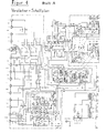
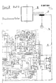
Das beschriebene Anwendungsbeispiel ist der Anmeldung als Schalt-Blockdiagramm beigefügt.The application example described is attached to the application as a circuit block diagram.
Um die Verbindung mit der Potentialausgleichsschiene oder dem Gebäudeerder herzustellen, können z.B. auch die metallenen Rohre von Wasser und Heizung die Aufgabe als Potentialausgleichsverbindung übernehmen.In order to establish the connection with the equipotential bonding bar or the building earth, e.g. the metal pipes of water and heating also take on the task of equipotential bonding.
Läßt sich z.B. bei der nachträglichen Einrichtung der Erfindung in Gebäuden oder Wohnräumen ein ausreichend geringer Widerstand an einem Metallrohr für Wasser oder Heizung messen (zur Messung vgl. Ausbildungsmappe Elektroinstallation, Baade u.a., Heidelberg 1985) so kann die Potentialausgleichsleitung sofort an eines dieser Rohre elektrischleitend befestigt werden. Dies stellt den Potentialausgleich erfindungsgemäß her.Can e.g. When subsequently installing the invention in buildings or living rooms, measure a sufficiently low resistance on a metal pipe for water or heating (for the measurement, see the training course in electrical installation, Baade et al., Heidelberg 1985), so the equipotential bonding line can be attached to one of these pipes in an electrically conductive manner. This establishes the equipotential bonding according to the invention.
Zeigt sich hier ein zu hoher elektrischer Widerstand, so können die Rohre in der Regel doch benutzt werden, nur muß dann im Hausanschlußraum eine leitende Verbindung vom benutzten Rohrsystem zur Potentialausgleichsschiene oder zum Gebäudeerder verlegt werden.If there is too high an electrical resistance here, the pipes can usually be used, only then a conductive connection from the pipe system used to the equipotential bonding rail or to the building earth must be laid in the house connection room.
Ausgezeichnete Linearisierungsergebnisse zeigten sich bei Widerstandswerten der Ausgleichsleitung die 5 0,005 Ω sind; prinzipiell bedingen geringere Widerstandswerte auch einen verbesserten Potentialausgleich.Excellent linearization results were shown with resistance values of the compensating line which are 5 0.005 Ω; in principle, lower resistance values also mean an improved equipotential bonding.
Für die Verwendung innerhalb von Wohnräumen ist ergänzend darauf hinzuweisen, daß zur Anwendung der Erfindung keine taudicken und teuren Kabel verlegt werden müssen.For use within living rooms, it should also be pointed out that no thick and expensive cables have to be laid to use the invention.
Es wird im Handel z.B. eine zweiadrige Litze (4 mm2), die insgesamt 8 mm2 Querschnitt aufweist, angeboten. Eine 10 m-Rolle dieses flexiblen Kabels, das in verschiedenen Farben erhältlich ist und als Lautsprecherkabel angeboten wird, kostet(e) 1986 15 DM. Diese Litze hat die bescheidenen Abmessungen von ca. 3,5 mm mal 7 mm.A two-core strand (4 mm 2 ), which has a total cross section of 8 mm 2 , is offered commercially. A 10 m roll of this flexible cable, which is available in different colors and is offered as a loudspeaker cable, costs (DM) 15 DM in 1986. This strand has the modest dimensions of approx. 3.5 mm by 7 mm.
Bei der Anwendung der Erfindung innerhalb der Gerätekombination Verstärker-Lautsprecher muß sichergestellt sein, daß die elektrischen Verbindungskabel des Lautsprechers (Phase und Masse) beim Anschluß nicht vertauscht werden, weil es ansonsten zum elektrischen Kurzschluß innerhalb des Lautsprechersignalstromkreises kommen würde. D.h. anschlußmäßig darf es nicht zur Phasenvertauschung kommen.When using the invention within the amplifier-loudspeaker combination, it must be ensured that the electrical connection cables of the loudspeaker (phase and ground) are not interchanged when connecting, because otherwise there would be an electrical short circuit within the loudspeaker signal circuit. I.e. in terms of connection, there must be no phase reversal.
Bei dem meßtechnischen Nachweis - der Verringerung von Störspannungen im Lautsprecher-Signalstromkreis - wurden die Störspannungen und die Signalspannung gleichzeitig gemessen und auf dem Ozilloskop dargestellt.In the metrological verification - the reduction of interference voltages in the loudspeaker signal circuit - the interference voltages and the signal voltage were measured simultaneously and displayed on the oscilloscope.
Als Signalspannungsquelle diente die Test CD DHFI Schallplatte Nr. 9 (410741-2) sowie ein mit der Erfindung nachgerüsteter Verstärker, dessen Schaltbild, ohne und mit Potentialausgleichsleitung, der Anmeldung beigefügt ist.Test CD DHFI record no. 9 (410741-2) and an amplifier retrofitted with the invention served as the signal voltage source. The circuit diagram, without and with equipotential bonding line, is attached to the application.
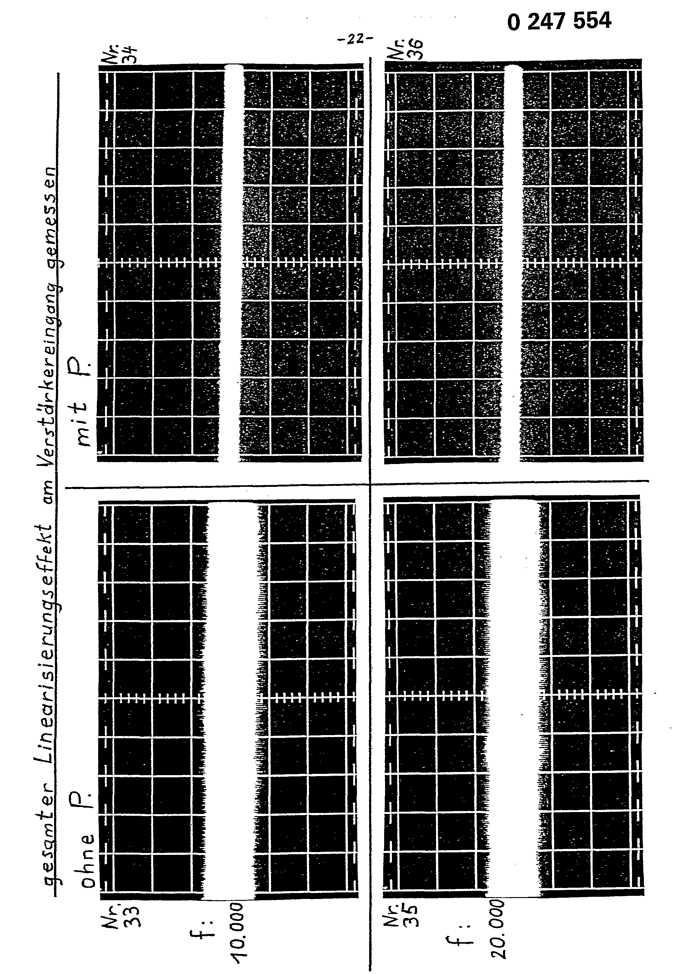
Die beigefügte Bilderserie zeigt die 0szillosgramme der Störspannungen (jeweils oben auf dem Bild) und der Sinuston-Signalspannung (jeweils unten auf dem Bild).The attached picture series shows the oscillosgrams of the interference voltages (each on the top of the picture) and the sine wave signal voltage (each on the bottom of the picture).
Jeweils zwei Bilder der gleichen Signalfrequenz sind nebeneinandergestellt; links das Bild ohne und rechts das Bild mit Potentialausgleich.Two pictures of the same signal frequency are juxtaposed; on the left the picture without and on the right the picture with equipotential bonding.
Da auch die Signalspannung bei den nebeneinandergestellten Bildern jeweils gleich ist, stellt die linearer-verlaufende Störspannungskurve der rechten Bilder die Linearisierungswirkung der Erfindung auch optisch dar; der Kurvendiagrammunterschied, links oben zu rechts oben, auf den Bildern entspricht der Verringerung der Störspannungen durch die Potentialausgleichsleitung.Since the signal voltage is also the same for each of the images placed next to one another, the linear interference voltage curve of the images on the right also represents the linearization effect of the invention optically; the curve diagram difference, top left to top right, on the pictures corresponds to the reduction of interference voltages through the equipotential bonding line.
Die beigefügte Tabelle verdeutlicht die Meßergebnisse und den Linearisierungseffekt zahlenmäßig.The attached table illustrates the measurement results and the linearization effect in numbers.
Aus den Bildern und den Daten der Tabelle ist die Zunahme der induzierten Gegenströme der Lautsprecher bei steigender Frequenz ablesbar. Gleichzeitig zeigen Bilder und Tabelle die Abnahme der Störspannungen bei allen Frequenzen aufgrund der linearisierenden Wirkung der Potentialausgleichsleitung.The increase in the induced counter currents of the loudspeakers with increasing frequency can be read from the pictures and the data in the table. At the same time, pictures and table show the decrease in interference voltages at all frequencies due to the linearizing effect of the equipotential bonding line.
Diese Störspannungen betrugen bei den Messungen - je nach Frequenz - 0,2% bis über 4% der Signalspannung. Die Erfindung reduzierte die Störspannungen insgesamt auf etwa ein Fünftel oder 20% (siehe auch Teil B, Blatt 16ff.)


- Nr.: BildnummerNo .: picture number
- f: Frequenz des Sinustonsignalsf: frequency of the sine signal
- P:-,X, -ohne Potentialausgleich, X mit PotentialausgleichP: -, X, -without equipotential bonding, X with equipotential bonding
- V sign: Signalspannung des Sinusstroms am sogenannten Pluspol des Lautsprechers, als Oszillogramm unten auf den Bildern dargestellt.V sign: signal voltage of the sine current at the so-called positive pole of the loudspeaker, shown as an oscillogram in the pictures below.
- milli- V stör: signalfrequente vom Lautsprecher erzeugte Störspannung, am sog. Minuspol des Lautsprechers; als Oszillogramm oben auf den Bildern dargestellt.milli- V disturbance: signal-frequency interference voltage generated by the loudspeaker, at the so-called minus pole of the loudspeaker; shown as an oscillogram at the top of the pictures.
- % Stör.: Prozentanteil dieser Störspannungen im Verhältnis zur Sinussignalspannung.% Interference: percentage of this interference voltage in relation to the sine signal voltage.
- Red. Stör.: Reduzierung der durch den Lautsprecher produzierten Störspannung aufgrund der Potentialausgleichsleitung in %.Red. Stör .: Reduction of the interference voltage produced by the loudspeaker due to the equipotential bonding line in%.
Bei den Messungen hatte die verwendete Potentialausgleichsleitung einen 5fachen größeren Querschnitt als die Lautsprecherzuleitung pro Phase aufweist und entsprechend einen fünffachen geringeren elektrischen Widerstand, als eine der beiden Teiladern der Lautsprecherzuleitung aufweist.During the measurements, the equipotential bonding line used had a
Der elektrische Widerstand des Netzschutzleiters betrug 0,6 Ohm. Der elektrische Widerstand der Potentialausgleichsleitung betrug ca. 0,002 Ohm.The electrical resistance of the mains protective conductor was 0.6 ohms. The electrical resistance of the equipotential bonding line was approximately 0.002 ohms.
Für diese Messungen wurde das verwendete Oszilloskop nicht mehr über dessen speisende Licht-Steckdose geerdet, da deren Netzerde ja selbst Potentialdifferenzen aufweist. Das Gerät wurde deshalb über die Potentialausgleichsleitung quasi ideal geerdet.For these measurements, the oscilloscope used was no longer grounded via its supplying light socket, since its network earth itself has potential differences. The device was therefore almost ideally grounded via the equipotential bonding line.
(Die Messungen und 0szillogramme Nr. 1 bis Nr. 12 zeigen deshalb nicht die gesamte Linearisierungswirkung der Erfindung innerhalb des Lautsprechersignalstromkreises, weil bei diesen Messungen das Oszilloskop normal über die Licht-Steckdosen geerdet war.)(The measurements and oscillograms No. 1 to No. 12 therefore do not show the entire linearizing effect of the invention within the loudspeaker signal circuit, because in these measurements the oscilloscope was normally grounded via the light sockets.)
Die Oszillogrammbilder Nr. 13 bis Nr. 24 stellen die gesamte Linearisierungswirkung, - am sogenannten Minuspolanschluß des Lautsprechers gemessen - dar.The oscillogram images No. 13 to No. 24 represent the total linearization effect, measured at the so-called minus pole connection of the loudspeaker.
Sie zeigen für sechs verschiedene Signalfrequenzen die Störspannungen ohne Potentialausgleichsleitung (linkes Bild) und mit Potential ausgleichsleitung (rechtes Bild); bei jeweils absolut gleicher Einstellung aller Geräte für das linke und rechte Oszillogramm. Die Oszillogramme Nr. 25 bis Nr. 36 zeigen entsprechend die Störspannungen am Eingang des Verstärkers (gemessen am Massepunkt des benutzten Reservesignaleingangs, Aux.)They show the interference voltages for six different signal frequencies without equipotential bonding line (left picture) and with equipotential bonding line (right picture); with absolutely the same setting of all devices for the left and right oscillogram. The oscillograms No. 25 to No. 36 accordingly show the interference voltages at the input of the amplifier (measured at the ground point of the reserve signal input used, Aux.)
Die Einstellung des Oszilloskops war für alle Oszillogramme gleicher Frequenz gleich (Daten siehe Tabelle).The setting of the oscilloscope was the same for all oscillograms of the same frequency (data see table).
Die gesamte Linearisierungswirkung beträgt (nach den Oszillogrammen Nr. 13 bis Nr. 36) mindestens 75%; also Reduzierung der Störspannungen auf ca. 25%.The total linearization effect is (according to oscillograms No. 13 to No. 36) at least 75%; thus reducing the interference voltages to approx. 25%.
* Bei den Oszillogrammen Nr. 13 bis Nr. 36 wurde die Zeiteinstellung pro cm des Oszilloskops nicht jeweils variiert.


Claims (5)
Kennzeichnender Teil:
Dadurch gekennzeichnet, daß zwischen den Massepunkten der zu linearisierenden Stromkreise und der Potentialausgleichsschiene (oder einem hiermit in Verbindung stehenden Erder) des speisenden Netz-Primärstromkreises (oder auch einem separaten Erder) eine leitende Verbindung hergestellt wird, die gegenüber dem hierfür üblich zur Verfügung stehenden Erdschutzleiter der Licht-Steckdosen des speisenden Netz-. stromkreises einen sehr geringen - möglichst geringen - elektrischen Widerstand aufweist.
Oberbegriff des Unteranspruchs:1.Special compensation line for switching off potential differences and for signal linearization between the supplying mains primary circuit, the mains-connected secondary circuit and the further secondary signal circuits to be linearized, as well as within these circuits, in particular for amplifiers, loudspeakers and generally for electrical equipment, i.e. all equipment in which linearity is important or potential differences have a disruptive effect. The equalization line creates a voltage equalization within the various circuits, but also between them, via the so-called equipotential bonding bar (or an equivalent earthing conductor) of the electrical consumer system - within the scope of which the invention is applied.
Characteristic part:
Characterized in that a conductive connection is established between the earth points of the circuits to be linearized and the equipotential bonding bar (or an earth connected to it) of the supplying mains primary circuit (or also a separate earth), which is compared to the earth protective conductor commonly available for this purpose of the power outlet's light sockets. circuit has a very low - as low as possible - electrical resistance.
Preamble of the dependent claim:
Oberbegriff des Unteranspruchs:1) For the equipotential bonding bar, see pages 2/3 below. Light sockets of the supplying mains primary circuit of the electrical building installation within whose mains power system the invention is applied. The compensating line has in particular a much larger cross section than the earth conductor cable, which is installed in buildings with a cross section of 1.5 mm 2 from the socket used in each case for the primary current draw to the equipotential bonding bar of the electrical consumer system in buildings. The equalization line leads from the earth points of the device circuits to be linearized to the equipotential bonding bar or to an equivalent earthing conductor of the building in which the invention is used. The devices in which the invention is used are to be set up or retrofitted on the device side with the invention and connected to the equipotential bonding bar (or an equivalent earth electrode).
Preamble of the dependent claim:
Applications Claiming Priority (2)
| Application Number | Priority Date | Filing Date | Title |
|---|---|---|---|
| DE3617798 | 1986-05-27 | ||
| DE19863617798 DE3617798A1 (en) | 1986-02-19 | 1986-05-27 | Special compensation line for eliminating potential differences and for linearising signals |
Publications (2)
| Publication Number | Publication Date |
|---|---|
| EP0247554A2 true EP0247554A2 (en) | 1987-12-02 |
| EP0247554A3 EP0247554A3 (en) | 1989-06-07 |
Family
ID=6301723
Family Applications (1)
| Application Number | Title | Priority Date | Filing Date |
|---|---|---|---|
| EP87107551A Withdrawn EP0247554A3 (en) | 1986-05-27 | 1987-05-23 | Special balancing wire to eliminate potential differences and to make signals linear |
Country Status (1)
| Country | Link |
|---|---|
| EP (1) | EP0247554A3 (en) |
Cited By (2)
| Publication number | Priority date | Publication date | Assignee | Title |
|---|---|---|---|---|
| AU607087B2 (en) * | 1988-11-29 | 1991-02-21 | Hitachi Limited | An arrangement for preventing inductive interference in electric car |
| EP0385258A3 (en) * | 1989-02-28 | 1992-07-08 | Hans Havenith | Circuitry cancelling potential differences and for signal linearisation |
Family Cites Families (2)
| Publication number | Priority date | Publication date | Assignee | Title |
|---|---|---|---|---|
| FR851645A (en) * | 1938-09-20 | 1940-01-12 | Improvements to electronic tube amplifiers | |
| US3204201A (en) * | 1960-05-18 | 1965-08-31 | Vidar Corp | Shielded circuit |
-
1987
- 1987-05-23 EP EP87107551A patent/EP0247554A3/en not_active Withdrawn
Cited By (2)
| Publication number | Priority date | Publication date | Assignee | Title |
|---|---|---|---|---|
| AU607087B2 (en) * | 1988-11-29 | 1991-02-21 | Hitachi Limited | An arrangement for preventing inductive interference in electric car |
| EP0385258A3 (en) * | 1989-02-28 | 1992-07-08 | Hans Havenith | Circuitry cancelling potential differences and for signal linearisation |
Also Published As
| Publication number | Publication date |
|---|---|
| EP0247554A3 (en) | 1989-06-07 |
Similar Documents
| Publication | Publication Date | Title |
|---|---|---|
| EP0525703B1 (en) | Connector for local networks | |
| EP1442308B1 (en) | Impedance stabilization network for determining the electromagnetic interfering radiation of a modem | |
| DE4136314C2 (en) | Arrangement for suppressing interference in electronic circuits | |
| EP2863553B1 (en) | Coupling device for coupling a powerline device and a measurement device to a power supply network, and a measurement node | |
| WO2000060366A1 (en) | Current meter | |
| DE102013106702A1 (en) | Method and device for detecting an arc | |
| DE102007013634A1 (en) | Device for measuring a direct current component of a current flowing in conductors of alternating current paths superimposed by an alternating current component | |
| EP2362514B1 (en) | Device for reducing earth leakage current | |
| DE19940284C1 (en) | Electrical and/or magnetic field compensation device e.g. for electrical reception or measuring device, uses compensation conductor extending alongside electrical conductor providing interference field | |
| DE3617798C2 (en) | ||
| DE3708731C1 (en) | Electrical circuit arrangement for detecting noise pulses in high-voltage systems | |
| DE2355014C2 (en) | Circuit arrangement for preventing undesired feedback for a remotely powered repeater in a communication system | |
| EP0014969B1 (en) | Input circuit for receiver-side line terminal apparatus of a telecommunication system | |
| DE1285560B (en) | DC remote feed system | |
| DE2431485C3 (en) | Circuit arrangement for obtaining a frequency-variable, ground-potential-free and symmetrical output voltage in a device used in electrical measurement and communication technology | |
| DE4030397C1 (en) | ||
| DE3151143C2 (en) | Circuit arrangement for the suppression of signals on line sections | |
| DE4402351C2 (en) | Device for suppressing hum and interfering interference on audio connecting lines | |
| DE4003708A1 (en) | Ground line impedance elimination circuit - has cable of lower specific resistance than signal lines | |
| AT509840B1 (en) | SUPPRESSION OF OVERVOLTAGE CAUSED BY INDIRECT LIGHTNING | |
| EP0385258A2 (en) | Circuitry cancelling potential differences and for signal linearisation | |
| DE19936873B4 (en) | circuitry | |
| DE19529302A1 (en) | Device for compensating harmonic currents of a transmission path consisting of several conductors | |
| AT512668B1 (en) | Arrangement for transmitting data in a power supply network | |
| WO2013131744A1 (en) | Filter assembly for a shielded cable connection |
Legal Events
| Date | Code | Title | Description |
|---|---|---|---|
| PUAI | Public reference made under article 153(3) epc to a published international application that has entered the european phase |
Free format text: ORIGINAL CODE: 0009012 |
|
| AK | Designated contracting states |
Kind code of ref document: A2 Designated state(s): AT BE CH DE FR GB IT LI LU NL SE |
|
| PUAL | Search report despatched |
Free format text: ORIGINAL CODE: 0009013 |
|
| AK | Designated contracting states |
Kind code of ref document: A3 Designated state(s): AT BE CH DE FR GB IT LI LU NL SE |
|
| STAA | Information on the status of an ep patent application or granted ep patent |
Free format text: STATUS: THE APPLICATION IS DEEMED TO BE WITHDRAWN |
|
| 18D | Application deemed to be withdrawn |
Effective date: 19891201 |