EP0247442A2 - Rotating magnetic head device in magnetic recording and reproducing apparatus - Google Patents
Rotating magnetic head device in magnetic recording and reproducing apparatus Download PDFInfo
- Publication number
- EP0247442A2 EP0247442A2 EP87106966A EP87106966A EP0247442A2 EP 0247442 A2 EP0247442 A2 EP 0247442A2 EP 87106966 A EP87106966 A EP 87106966A EP 87106966 A EP87106966 A EP 87106966A EP 0247442 A2 EP0247442 A2 EP 0247442A2
- Authority
- EP
- European Patent Office
- Prior art keywords
- tape
- head device
- fixed cylinder
- rotating
- magnetic
- Prior art date
- Legal status (The legal status is an assumption and is not a legal conclusion. Google has not performed a legal analysis and makes no representation as to the accuracy of the status listed.)
- Granted
Links
Images


Classifications
-
- G—PHYSICS
- G11—INFORMATION STORAGE
- G11B—INFORMATION STORAGE BASED ON RELATIVE MOVEMENT BETWEEN RECORD CARRIER AND TRANSDUCER
- G11B5/00—Recording by magnetisation or demagnetisation of a record carrier; Reproducing by magnetic means; Record carriers therefor
- G11B5/48—Disposition or mounting of heads or head supports relative to record carriers ; arrangements of heads, e.g. for scanning the record carrier to increase the relative speed
- G11B5/52—Disposition or mounting of heads or head supports relative to record carriers ; arrangements of heads, e.g. for scanning the record carrier to increase the relative speed with simultaneous movement of head and record carrier, e.g. rotation of head
- G11B5/53—Disposition or mounting of heads on rotating support
-
- G—PHYSICS
- G11—INFORMATION STORAGE
- G11B—INFORMATION STORAGE BASED ON RELATIVE MOVEMENT BETWEEN RECORD CARRIER AND TRANSDUCER
- G11B15/00—Driving, starting or stopping record carriers of filamentary or web form; Driving both such record carriers and heads; Guiding such record carriers or containers therefor; Control thereof; Control of operating function
- G11B15/60—Guiding record carrier
- G11B15/61—Guiding record carrier on drum, e.g. drum containing rotating heads
- G11B15/615—Guiding record carrier on drum, e.g. drum containing rotating heads inside container
-
- G—PHYSICS
- G11—INFORMATION STORAGE
- G11B—INFORMATION STORAGE BASED ON RELATIVE MOVEMENT BETWEEN RECORD CARRIER AND TRANSDUCER
- G11B15/00—Driving, starting or stopping record carriers of filamentary or web form; Driving both such record carriers and heads; Guiding such record carriers or containers therefor; Control thereof; Control of operating function
- G11B15/60—Guiding record carrier
- G11B15/66—Threading; Loading; Automatic self-loading
- G11B15/665—Threading; Loading; Automatic self-loading by extracting loop of record carrier from container
- G11B15/6653—Threading; Loading; Automatic self-loading by extracting loop of record carrier from container to pull the record carrier against drum
Definitions
- the prior art has been problematic in the points of machining and assembling costs for the reasons that the head rotating member needs to be formed with the spiral grooves of complicated shape and that the gaps between the grooves and the fixed cylinders need to be controlled to predetermined narrow intervals. Moreover, since the air is blown out uniformly over the whole outer peripheries of the cylinders, the air layer becomes thicker at the start part of tape winding where the tape exhibits a low tension. As a result, an ununiform air film is formed, and nonuniformity in the magnetic contact between each rotating head and the tape arises to cause nonuniformity in the physical contact of the two. This has posed the problem that degradation in the contact between the tape and the head, namely, the head-to-tape contact is prone to be incurred.
- the reasons why the subchassis is moved after the loading of the group of tape guides in predetermined amounts as stated above, are to define within the opening 8 a space into which the rotating head device 2 gets and to prevent the slack of the tape with the subchassis checked from moving at the time of the completion of the unloading.
- Fig. 7 is a plan view showing the basic configuration of the subchassis 7.
- Numeral 51 designates a delivery reel bed which engages the delivery reel 4, and numeral 52 a take-up reel bed which engages the take-up reel 5.
- the cassette 6 when the cassette 6 is placed on the subchassis 7, it is positioned and held by positioning pins 53a, 53b and leveling pins 54a, 54b.
- three slots 50a, 50b and 50c are provided at end parts of the subchassis 7, and this subchassis is so supported as to be slidable in the directions of the slots 50a, 50b and 50c by means of guide pins 49a, 49b and 49c disposed on the main chassis 1, respectively.
- a cam groove 55 is a guide groove for driving the subchassis 7, and the driving method will be described with reference to Fig. 8.
- Fig. 11(a) and Fig. 11(b) are conceptual diagrams for elucidating the effect according to the present invention, and the former illustrates the prior art, while the latter illustrates the present invention.
- Fig. 11(a) with the prior art, especially in the tape winding end part of high tape tension, air films are difficult to be formed between the tape 3 and the respective cylinders 34, 35, and the tape 3 comes into touch with the end-parts of the upper fixed cylinder 35 and the lower fixed cylinder 34.
- desired air layers can be formed between the tape and the cylinders even at the tape winding end part.
- the rotary disc 307 is fixed to the upper part of the rotary member 304 by bolts 71, the plurality of head bases 310 are fixed to the upper surface of the rotary disc 307 by bolts 72, and the magnetic head 309 protruding out beyond the tape traveling plane 308 are carried on the head bases 310.
- the flat FG coil 315 Carried on the lower surface of the flat portion of the stator base 313 parallel to the rotary disc 307 is the flat FG coil 315, in opposition to which the flat FG magnet 316 is arranged. More specifically, the FG magnet 316 is carried on the upper surface of the flat magnet holder 317, the flat motor magnet 318 is carried on the lower surface of the magnet holder 317, and the flat motor coil 319 is carried on the inside bottom of the lower fixed cylinder 34 in opposition to the motor magnet 318.
- a motor rotor unit is constructed of the FG magnet 316, the magnet holder 317, the motor magnet 318, and the motor rotor base 320 fixed to the magnet holder 317, and it is fixed to the rotary member 304 by screws.
- the radial vibrations of the motor magnet 318 and the FG magnet 316 with respect to the axis of rotation of the rotary member 304 can be adjusted.
- rotating magnetic heads capable of coping with multi-channeling can be realized, and when the device is installed on a magnetic recording and reproducing apparatus', it is permitted to overlap a tape cassette, and the rotating head device which can realize the magnetic recording and reproducing apparatus of small horizontal area can be provided.
Abstract
Description
- The present invention relates to a magnetic recording and reproducing apparatus, and more particularly to a rotating magnetic head (hereinbelow, simply termed "rotating head") device which is well suited to reduce the size of the apparatus and to stabilize the traveling of a tape and prevent the damage of the tape.
- The present invention further relates to a rotating head device, and more particularly to a rotating head device which has built-in large-sized rotary transformers coping with the multi-channeling of signals and which is well suited for a smaller size owing to the reduction of the diameters of cylinders.
- Nowadays, there are high needs for reduction in the sizes of video tape recorders (VTR's), and various measures for reducing the sizes of mechanisms have been proposed. With any of the methods, however, the geometries of the entire mechanism are substantially determined by the sizes of a cassette and a rotating head device.
- In this regard, an example which pursues the utmost limits of the size of the mechanism for system specifications such as the shapes of the cassette and the rotating head device is as disclosed in the official gazette of Japanese Patent Application Laid-open No. 171070/1984. This measure consists in that, as shown in Fig. 1 of the drawings annexed herewith, a part (a
ring 106 in the figure) of the rotating head device is pressed into (caused to overlap) thefront opening 104 of thecassette 102, thereby to reduce the depth of an apparatus. Such a measure is effective for a system, for example, the VTR of 8mm-FORMAT in which the opening of the cassette is large. In the figure,numeral 101 designates a tape guide drum, andnumeral 103 and designate tape part, respectively. - The prior art, however, has the following problems (1), (2), (3) and (4), which are more serious especially in a system of so-called wide-angle winding wherein a tape is wound round a rotating head over an angular extent of at least 180°:
- (1) In order to insert the rotating head device into the opening of the cassette, this rotating head device needs to be arranged at a low position while avoiding the inner lid and top case of the cassette. This increases the height of the whole apparatus, and forms a factor obstructive of the thinning of the apparatus.
- (2) For the purpose of arranging the rotating head device which is basically cylindrical, at the highest possible position within the cassette opening, preferably the angle of inclination of the rotating head device with respect to a chassis is made small so as to flatten the top surface of the rotating head device. Since, however, a tape is wound obliquely to the rotating head device, the heights of the tape parts obliquely traveling on the entrance side and exit side of the rotating head device become different. Accordingly, the traveling path of the tape becomes a multilevel one, and in particular, the tape lowers on the exit side, so that the whole apparatus thickens.
- (3) In executing multilevel tape loadings on both the sides of the rotating head device, a loading mechanism becomes complicated, and this hampers reducing the size and lightening the weight of the apparatus.
- (4) In the aforementioned case where the angle of winding of the tape round the rotating head is large, there is a place in which the traveling direction of the tape changes acutely, and hence, the smooth traveling performance of the tape is liable to degrade.
- As disclosed in the official gazette of Japanese Patent Application Laid-open No. 150125/1980, another prior-art example has pursued the thinning of a rotating head device alone and therefore has a structure wherein electromagnetic components such as brushless motor parts, frequency generator (FG) parts and a rotary transformer are distributively arranged above and below the rotating plane of magnetic heads, namely, an arrangement wherein at least the rotary transformer and the brushless motor are distributed above and below a rotating drum on which the magnetic heads are mounted.
- It is not considered, however, that a tape cassette and the rotating head device combined with each other cannot be skillfully caused to overlap on account of the protrusion of, e. g., the lid of the tape cassette which is opened for drawing out a magnetic tape, so the combination hampers reduction in the horizontal area of the mechanism portion of a magnetic recording and reproducing apparatus carrying the rotating head device. That is, the prior art does not take it into account that the overlap between the tape cassette and the rotating head device is hampered by the protrusion of, e. g., the tape cassette lid to be opened for drawing out the tape, and it has had the problem that the reduction of the horizontal area of the mechanism portion of the magnetic recording and reproducing apparatus carrying the rotating head device is impeded.
- Meanwhile, in a fixed cylinder device wherein the upper and lower cylinders of a rotating head device are fixed, an air film formed between a tape and the cylinders has heretofore been thin as compared with one in a rotary cylinder system. This is attributed to the absence of the effect of producing the air film as in the conventional rotary cylinder system. In the fixed cylinder device, accordingly, the traveling load of the tape enlarges due to a less smoothing action based on the air film, and such problems as obstruction to stable traveling and damages to the tape have been prone to occur. These drawbacks have become more conspicuous as the tape has been thinned for a lower rigidity and roughened for a higher friction factor with raise in the density of recording. Developments have therefore been made for forming a sufficient and stable air-smoothing layer also in the fixed cylinder device. An example thereof is as disclosed in the official gazette of Japanese Patent Application Laid-open No. 36361/1984. As shown in Fig. 2 of the drawings annexed herewith, the disclosed device is so constructed that
spiral grooves fixed cylinders portion 216 including rotating heads, so as to form an air film between a tape and the cylinders. As a result, the contact of the tape with the cylinders is avoided or relieved, and the damages of the tape are eliminated, so that the qualities of recording and reproduction can be enhanced. - In Fig. 2,
numeral 214 indicates a rotary shaft,numerals 203 indicate the magnetic heads, andnumeral 218 indicates a coil. - The prior art, however, has been problematic in the points of machining and assembling costs for the reasons that the head rotating member needs to be formed with the spiral grooves of complicated shape and that the gaps between the grooves and the fixed cylinders need to be controlled to predetermined narrow intervals. Moreover, since the air is blown out uniformly over the whole outer peripheries of the cylinders, the air layer becomes thicker at the start part of tape winding where the tape exhibits a low tension. As a result, an ununiform air film is formed, and nonuniformity in the magnetic contact between each rotating head and the tape arises to cause nonuniformity in the physical contact of the two. This has posed the problem that degradation in the contact between the tape and the head, namely, the head-to-tape contact is prone to be incurred.
- An object of the present invention is to provide a device which is well suited especially for reducing the size of a magnetic recording and reproducing apparatus and for stabilizing the traveling of a tape and preventing the damages of the tape.
- A further object of the present invention is to provide a device in which comparatively large-sized rotary transformers to cope with the multi-channeling of recording/reproduction signals can be built and which is well suited for reducing the size of a cylinder in order to realize high-density packaging of constituents.
- To the accomplishment of the above objects, the present invention is constructed as follows:
- (1) The cylinder is fabricated as a fixed cylinder which does not rotate with magnetic heads, and the part of the cylinder round which the magnetic tape is not wound is formed with a recess, in which the inner lid, the top case or the like of a tape cassette is arranged in an overlapping manner (that is, the aforementioned part of the cassette is inserted), thereby making it possible to reduce the size of the apparatus.
- (2) Furthermore, the fixed cylinder is configured of an upper fixed cylinder and a lower fixed cylinder, the upper fixed cylinder is mounted on the upper part of a fixed shaft standing upright centrally of the lower fixed cylinder, and the recess is formed on the side of the upper fixed cylinder confronting the cassette. Thus, the cassette and the fixed cylinder are caused to overlap each other, and electromagnetic components such as a rotary member rotatable about the fixed shaft, a rotary disc carrying the plurality of magnetic heads, and the flat opposition type rotary transformers, are received within the lower fixed cylinder, thereby making it possible to heighten the packaging density of the constituents and to reduce the size of the apparatus.
- (3) Besides, the gap between the fixed cylinder and the surface of the rotary disc carrying' the rotating heads is put into a wedge shape which is broad at the start part of magnetic tape winding and which narrows toward the end part of the winding. Thus, owing to the varying gap, the magnitude of the air pressure between the rotary disc and the fixed cylinder is'controlled to regulate the discharge amount of air, thereby to obviate the drawbacks concerning the air film which is formed between the magnetic tape and the cylinder in the prior-art fixed cylinder device, and to permit stabilizing the tape traveling and preventing the tape damages.
-
- Fig. 1 is a plan view of a mechanism for loading a magnetic tape in a magnetic recording and reproducing apparatus in a prior art;
- Fig. 2 is a sectional view showing an example of a rotating head mechanism in a prior art;
- Fig. 3 is a plan view showing the general construction of a magnetic recording and reproducing apparatus in an embodiment of the present invention;
- Fig. 4 is a plan view of a state under which the loading of a magnetic tape has been completed in the apparatus shown in Fig. 3;
- Fig. 5 is a side view showing the relation between a cassette and a rotating head device for elucidating an embodiment of the present invention;
- Fig. 6 is a sectional view of a rotating head device in an embodiment of the present invention;
- Fig. 7 is a plan view of a subchassis;
- Fig. 8 is a side view showing a subchassis driving portion;
- Fig. 9 is a perspective view of an upper fixed cylinder;
- Fig. 10 is an expansion plan showing the surface of the upper fixed cylinder opposing to a head mounting cylinder;
- Fig. 11(a) is a sectional view showing the relation between a rotating head device and a tape in a prior art, while Fig. 11(b) is a sectional view showing the relation between them in an embodiment of the present invention;
- Fig. 12 is a half vertical sectional view of a rotating head device according to an embodiment of the present invention;
- Fig. 13(a) is a schematic plan view of a magnetic recording and reproducing apparatus in which the rotating head device shown in Fig. 12 is installed, while Fig. 13(b) is a partial sectional side view thereof;
- Fig. 14 is a sectional view of the motor portion and frequency generator portion of a rotating head device according to another embodiment of the present invention; and
- Fig. 15 is a sectional view of the motor portion and frequency generator portion of a rotating head device according to still another embodiment of the present invention.
- Now, the embodiments of the present invention will be described with reference to the drawings.
- Fig. 3 is a general plan view of a magnetic recording and reproducing apparatus according to the present invention, and it shows a state before loading under which a
cassette 6 is inserted. In the figure,numeral 2 designates a rotating head device in which magnetic heads are mounted, numeral 3 a tape, numeral 4 a delivery reel, numeral 5 a take-up reel, andnumeral 6 the cassette in which thedelivery reel 4 and the take-up reel 5 having thetape 3 wound thereon are built. Thecassette 6 has anopening 8 inside thetape 3 which is extended at the front thereof. As will be stated later, thetape 3 extended at the front is covered with a lid in a state under which the cassette is drawn out of the apparatus. - On a
main chassis 1 with the rotatinghead device 2, etc. placed thereon, asubchassis 7 is slidably put as will be stated later. Thecassette 6 is set at a predetermined position shown in Fig. 3 on thesubchassis 7 by means of a cassette elevator (not shown). At this time, roller type tape guides 10 and 15, tilted tape guides 11 and 16, apinch roller 28, and pull-outrollers opening 8 of thecassette 6. - Meanwhile, on the
main chassis 1, there are placed aloading ring 9 which is turnably supported around the rotatinghead device 2, acapstan 26 which holds amotor 27 coaxially under it in order to drive thetape 3, and roller type tape guides 24 and 25. Theloading ring 9 is driven in a loading direction and an unloading direction through a speed-down mechanism etc. by a driving source such as the motor. The rollertype tape guide 10 and the tiltedtape guide 11 are planted on abase 12, and are supported so as to be turnable about apin 14 on theloading ring 9 through anarm 13. Likewise, the rollertype tape guide 15 and the tiltedtape guide 16 are planted on abase 17, and they are supported so as to be turnable about apin 19 on theloading ring 9 through anarm 18. Thebases roller 20 is disposed on anarm 21, which is turnably supported on themain chassis 1. Likewise, abase 30 on which thepinch roller 28 and the pull-outroller 29 are planted are supported on anarm 31, which is turnably supported on themain chassis 1. - Fig. 4 is a plan view of a state under which the loading of the tape has been completed in the magnetic recording and reproducing apparatus shown in Fig. 3. In loading the
tape 3, a group of tape guides consisting of the tape guides 10, 11, 15 and 16 are first moved by the turning of theloading ring 9, from the positions shown in Fig. 3 within theopening 8 of thecassette 6 to positions shown in Fig. 4 at which the winding of the tape round therotating head device 2 is completed. At the initial stage of the movement, the pull-outrollers pinch roller 28 are drawn out by the turning operations of thearms loading ring 9 is further turned a predetermined amount until the group of tape guides move nearly to the upper positions outside theopening 8 of thecassette 6 as shown in Fig. 4, thesubchassis 7 with thecassette 6 placed thereon is moved toward therotating head device 2. The movement of thesubchassis 7 ends when therotating head device 2 has entered the opening 8 a predetermined amount. Thereafter, theloading ring 9 is further turned, and the group of tape guides are precisely located and held at the positions shown in Fig. 4. The unloading operation of the tape is performed contrariwise to the above. Here, the reason why the movement of the subchassis is ended before the group of tape guides complete the loading, is to prevent the slack of the tape at the time of the completion of the loading. The reasons why the subchassis is moved after the loading of the group of tape guides in predetermined amounts as stated above, are to define within the opening 8 a space into which therotating head device 2 gets and to prevent the slack of the tape with the subchassis checked from moving at the time of the completion of the unloading. - The traveling path of the tape after the completion of the loading is as shown in Fig. 4. The
tape 3 comes out of thedelivery reel 4 and advances via the pull-outroller 20, atension pin 22 for detecting a tape tension, the rollertype tape guide 24, and the tiltedtape guide 16, at which the tape turns so as to rise, and then extends via the rollertype tape guide 15, the tiltedtape guide 11, and the rollertype tape guide 10 until it leads to therotating head device 2. Thetape 3 is wound here so as to gradually lower, and on the exit side of therotating head device 2, it is guided without any twist to the same level as that of a tape roll in thecassette 6. Thereafter, thetape 3 is taken up by the take-upreel 5 via the rollertype tape guide 25, thecapstan 26 and thepinch roller 28 between which the tape is held in pressed contact, and the pull-outroller 29. - Fig. 5 is a side view showing the relation between the cassette and the rotating head device for elucidating the essential portions of the magnetic recording and reproducing apparatus according to the present invention.
Numeral 1 designates the main chassis, numeral 2 the rotating head device, numeral 6 the cassette, numeral 7 the subchassis, numeral 8 the opening, numeral 32 a front lid, numeral 33 an inner lid, numeral 34 a lower fixed cylinder, numeral 35 an upper fixed cylinder,symbol 35a a recess, numeral 36 a rotating head, and numeral 85 a tape lead. - Referring to the figure, the
rotating head device 2 is basically composed of two elements; the lower fixedcylinder 34 and the upper fixedcylinder 35. The plurality ofrotating heads 36 are disposed in the interspace between the two opposing cylinders in a manner to slightly protrude beyond the outer peripheral surfaces of the cylinders. In addition, thecassette 6 is provided with a tape covering lid for the purpose of protecting the tape which is stretched in front of this cassette, and the structure of the lid is composed of thefront lid 32 and theinner lid 33 as illustrated in the figure. In the state in which thecassette 6 is set in the apparatus, thefront lid 32 and theinner lid 33 are open and overlie theopening 8, while in the state in which the cassette is detached from the apparatus, the tape is enveloped in thefront lid 32 and theinner lid 33. Accordingly, when it is intended to insert and arrange therotating head device 2 in theopening 8, the position of the lid structure forms a restrictive condition in height. In order to avoid this drawback, the part of the upper fixedcylinder 35 of therotating head device 2 opposing to thelids recess 35a. - Next, the construction of the
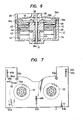
rotating head device 2 will be described with reference to Fig. 6. - Fig. 6 is a sectional view of the rotating head device according to the present invention.
Numeral 2 indicates the rotating head device, numeral 34 the lower fixed cylinder, numeral 35 the upper fixed cylinder,symbol 35a the recess,symbols symbols - Referring to the figure, the
shaft 37 is pressedly fitted in the lower fixedcylinder 34, and the upper fixedcylinder 35 is concentrically fixed to the upper end of the shaft. Thedisc 40 which is rotatably supported round theshaft 37 by thebearings cylinders bearings stopper 39. Therotor 43 of the motor is unitarily fixed to the lower part of thedisc 40, and it is arranged in opposition to thestator 42 fixed on the bottom of the lower fixedcylinder 34, so as to drive and rotate thedisc 40. Besides, themagnet 44 of an FG (Frequency Generator) for detecting the revolutions of the motor is mounted on therotor 43 and rotates together with therotor 43. It confronts theFG coil 45 mounted on theholder 46 disposed on the inner wall of the lower fixedcylinder 34, so as to generate the revolution signal of the motor. - Meanwhile, the rotating
cylinder 41 which carries theheads 36 is fixed on thedisc 40. Therotating side transformer 48 is bonded to the lower surface of therotating cylinder 41 and confronts the fixedside transformer 47 bonded to theholder 46, so as to transfer signals from and to theheads 36. - According to the construction of the rotating head device in the present embodiment, only the heads come into rotating contact with the tape, and the rotating accuracy of the heads are less susceptible to fluctuations in the tape tension, so that the driving motor can have its inertia lowered and its power lowered. Moreover, since the upper fixed
cylinder 35 is supported by theshaft 37, the concentricity between the upper and lower fixed cylinders can be readily attained, and the efficiency of assemblage can be raised. Further, since the recess of the upper fixed cylinder can be formed beforehand at the stage of the molding of the material of this cylinder, it does not incur increase in the cost of working. - Besides, the upper fixed
cylinder 35 has thelead 85 at the upper part thereof, and the stepped part of the lead radially protruding beyond the traveling plane of thetape 3 regulates the traveling height position of thetape 3. Accordingly, when themagnetic heads 36 scan thetape 3 obliquely during the traveling of the loadedtape 3, the rubbing forces thereof act in the direction of pressing thetape 3 against thelead 85. As a result, thetape 3 travels stably along thelead 85. - Usually a tape is wound obliquely and helically with respect to a rotating head device, and in ordinary systems, the tape enters from above and egresses downwards, that is, magnetic heads scan from the lower end side toward the upper end side of the tape. Accordingly, the wound state of the tape round the rotating head device is such that a part wound round an upper cylinder decreases more as the exit side of the device comes nearer.
- Accordingly, in case of performing the rotating head device as in the present invention, the traveling loop of the tape to be obliquely and helically wound round the rotating head device is set as a path which rises while turning toward the back of the rotating head device as viewed from a cassette on the entrance side of the rotating head device, so that the tape wound round the rotating head device at a part opposing to the front of the cassette becomes substantially even with a tape roll within the cassette. With such an arrangement, the rotating head device lies at a comparatively high position in an apparatus. Since, however, the portion of the upper cylinder confronting the cassette is recessed only at a part where the tape is not wound, the recess of the upper cylinder lies below the inner lid or top case of the cassette, and the rotating head device and the cassette can be arranged in overlapping fashion. It is accordingly possible to reduce the horizontal area of the apparatus to the utmost limit while the whole apparatus is thinned.
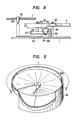
- Fig. 7 is a plan view showing the basic configuration of the
subchassis 7.Numeral 51 designates a delivery reel bed which engages thedelivery reel 4, and numeral 52 a take-up reel bed which engages the take-upreel 5. Referring to the figure, when thecassette 6 is placed on thesubchassis 7, it is positioned and held by positioningpins pins slots subchassis 7, and this subchassis is so supported as to be slidable in the directions of theslots guide pins main chassis 1, respectively. Acam groove 55 is a guide groove for driving thesubchassis 7, and the driving method will be described with reference to Fig. 8. - Fig. 8 is a side view illustrative of driving parts for the subchassis.
Numeral 1 denotes the main chassis, numeral 7 the subchassis, numeral 9 the loading ring, numeral 55 the cam groove, numeral 56 a gear, numeral 57 a shaft, numeral 58 a gear, numeral 59 a shaft, numeral 60 a shaft, numeral 61 a gear,symbols loading ring 9 is turned, thegear 56 which is supported turnable around the,-shaft 57 planted on themain chassis 1 is turned, and thegear 58 which is similarly supported turnable around theshaft 59 planted on thechassis 1 is turned. The lower surface of thegear 58 is provided with theshaft 60, around which thegear 61 is turnably supported. Thegear 61 is formed with thegear portions gear portion 61a having the larger number of teeth is in mesh with thegear 62 which is fixed to themain chassis 1. Thus, while revolving round theshaft 59 together with thegear 58, thegear 61 revolves on its axis or round theshaft 60. Further, thegear portion 61b meshes with thegear 63 which is supported turnable around theshaft 59. Therefore, thegear 63 revolves with a great deceleration according to the principle of a so-called mechanical paradox internal gear. Further, thegear 63 is unitarily furnished with thearm 64, and thepin 65 disposed at the distal end of thearm 64 engages thecam groove 55 of thesubchassis 7, so that thesubchassis 7 is slidden by the turning of thearm 64. Besides, thecam groove 55 consists of anarcuate part 55a and astraight part 55b as shown in Fig. 7. At the initial stage of the loading and at the completion of the loading, thepin 65 engages thearcuate part 55a of thecam groove 55. On this occasion, thepin 65 moves within thearcuate part 55a, but thesubchassis 7 does not slide. - Fig. 9 is a perspective view of the upper fixed cylinder, in which
numeral 35 designates the upper fixed cylinder and numeral 100 the opposition plane between the rotating heads and the head carrying cylinder, the illustration being vertically reversed to that of Fig. 5. Referring to Fig. 9, theopposition plane 100 of the upper fixedcylinder 35 opposing to the cylinder for carrying the rotating heads is in such a wedge shape that the clearance of the opposing plane from the rotating cylinder narrows gradually from the start part toward the end part of the winding. - Fig. 10 is an expansion plan illustrative of the opposition plane of the upper fixed
cylinder 35 opposing to thecylinder 41 for carrying themagnetic heads 36. Theopposition plane 100 gradually approaches thehead carrying cylinder 41 from the winding start part S toward the winding end part E of the tape winding T. In the illustrated example, the winding angle of thetape 3 is set at 221° in conformity with the standards of the VTR of 8mm-FORMAT. Accordingly, the air which is introduced by the high-speed rotation of therotating cylinder 41 has its pressure raised more by the wedge-shape effect of theopposition plane 100 as the end part E of the tape winding comes nearer. - Fig. 11(a) and Fig. 11(b) are conceptual diagrams for elucidating the effect according to the present invention, and the former illustrates the prior art, while the latter illustrates the present invention. As depicted in Fig. 11(a), with the prior art, especially in the tape winding end part of high tape tension, air films are difficult to be formed between the
tape 3 and therespective cylinders tape 3 comes into touch with the end-parts of the upper fixedcylinder 35 and the lower fixedcylinder 34. In contrast, as depicted in Fig. 11(b), according to the present invention, desired air layers can be formed between the tape and the cylinders even at the tape winding end part. Thus, according to the present invention, (1) the rotating head device can be arranged in the cassette opening in overlapping fashion to the utmost limit, so that the apparatus can be reduced in size and lightened in weight. (2) Since the tape traveling loop can be set as a path rising from the cassette on the entrance side of the rotating head device and as a parallel path on the exit side, the rotating head device can have its inclination angle reduced and can be arranged above the cassette, so that the apparatus can be thinned. Owing to the parallel traveling path on the exit side, the tape guide on the.exit side can be implemented as the roller type so as to decrease the load of tape traveling. It is accordingly possible to achieve the stable traveling of a thin tape and the reduction of the size and the lightening of the weight of the driving motor. Besides, (3) it is possible to discharge the air of low pressure at the start part of the tape winding and the air of high pressure at the end part of the winding, and the air film of uniform thickness can be formed over the entire tape winding. Accordingly, the traveling load of the tape can be decreased to stabilize the tape traveling and to prevent the damage of the tape, and a uniform and favorable head-to-tape contact can be attained over the entire tape winding. Further, (4) any new component is not required, and the opposition plane of the fixed cylinder can also be worked unitarily at the step of molding the material of this fixed cylinder, so that the present invention does not incur increases in the weight and the working cost. - Now, another embodiment of the present invention will be described.
- First, Fig. 12 is a half vertical sectional view of a rotating head device according to the other embodiment of the present invention, in which the vertical sectional view of the
rotating head device 2 is shown at the left of a center line 0, while the contour thereof is shown at the right of the center line 0. - Referring to Fig. 12, numeral 34 designates a lower fixed cylinder, and numeral 303 a fixed shaft which stands upright centrally of the lower fixed cylinder and whose axis corresponds to the center
line O. Numeral 304 indicates a rotary member which is rotatable about the fixedshaft 303, numeral 305 radial ball bearings, numeral 306 a preload fixture which exerts a preload on theradial ball bearings 305, and numeral 307 a rotary disc which is fixed to therotary member 304 bybolts 71 and on which a plurality of magnetic heads 309 are carried. -
Numeral 308 denotes a tape traveling plane at the outer peripheries of cylinders, and numeral 310 a head base for supporting the magnetic heads 309. Numeral 311 denotes a rotating side rotary transformer, and numeral 312 a stationary side rotary transformer, and these rotary transformers constitute flat opposition type rotary transformers for transmitting signals to the magnetic heads 309. -
Numeral 313 represents a stator base, numeral 314 signal lines for connecting the heads, the stationary side rotary transformer, etc. with a circuit board (not shown), numeral 315 the FG coil of a frequency generator (hereinbelow, termed "FG") for controlling therotary disc 307, numeral 316 the FG magnet, numeral 317 a magnet holder, numeral 318 the motor magnet of a brushless motor for controlling the rotation of therotary disc 307, numeral 319 the motor coil of the brushless motor, and numeral 320 a motor rotor base. -
Numeral 35 indicates an upper fixed cylinder which is mounted on the upper part of the fixedshaft 303, numeral 322 a recess in a two-dot chain line which is formed in the upper fixedcylinder 35, numeral 323 an interspace which is defined between the upper fixedcylinder 35 and the lower fixedcylinder 34 and through which the magnetic heads 309 pass, numeral 324 a spacer, numeral 325 motor wiring, and numeral 326 FG wiring. - Next, the constructions of the various components will be described.
- The fixed
shaft 303 stands upright centrally of the lower fixedcylinder 34. Therotary member 304 has theradial ball bearings 305 fitted into the two places of the upper and lower parts thereof by such an expedient as pressing-in or quenching, whereby it is snugly fitted on the fixedshaft 303 so as to be rotatable about this fixed shaft. Thepreload fixture 306 is fixed to the fixedshaft 303 by setscrews under the state under which a downward load is exerted, whereby theradial ball bearings 305 are preloaded to suppress shaking in the thrust direction thereof. - The
rotary disc 307 is fixed to the upper part of therotary member 304 bybolts 71, the plurality ofhead bases 310 are fixed to the upper surface of therotary disc 307 bybolts 72, and the magnetic head 309 protruding out beyond thetape traveling plane 308 are carried on the head bases 310. - Mounted on the lower surface of the
rotary disc 307 is the flat, rotating side rotary transformer 311 which is electrically connected with the magnetic heads 309. Thestator base 313 fixed to the lower fixedcylinder 34 has a surface parallel to the lower surface of therotary disc 307, and is provided with an opening for holding a clearance relative to therotary member 304. Thisstator base 313 carries the flat, stationary siderotary transformer 312 on the upper surface of its flat portion parallel to the lower surface of therotary disc 307. In addition, thesignal lines 314 connected with the winding of the stationary siderotary transformer 312 are led out of therotating head device 2 through an opening 302A which is provided in the side wall of the lower fixedcylinder 34 avoiding thetape traveling plane 308, whereby they can be connected to a magnetic . signal recording/reproducing circuit (not shown) disposed outside. - Carried on the lower surface of the flat portion of the
stator base 313 parallel to therotary disc 307 is theflat FG coil 315, in opposition to which theflat FG magnet 316 is arranged. More specifically, theFG magnet 316 is carried on the upper surface of theflat magnet holder 317, theflat motor magnet 318 is carried on the lower surface of themagnet holder 317, and theflat motor coil 319 is carried on the inside bottom of the lower fixedcylinder 34 in opposition to themotor magnet 318. A motor rotor unit is constructed of theFG magnet 316, themagnet holder 317, themotor magnet 318, and themotor rotor base 320 fixed to themagnet holder 317, and it is fixed to therotary member 304 by screws. Thus, the radial vibrations of themotor magnet 318 and theFG magnet 316 with respect to the axis of rotation of therotary member 304 can be adjusted. - The rotor unit of the
rotating head device 2 of the present embodiment is constructed of theaforementioned rotary member 304,rotary disc 307, magnetic heads 309, head bases 310, rotating side rotary transformer 311,FG magnet 316,magnet holder 317,motor magnet 318 andmotor rotor base 320. - In the upper fixed
cylinder 35, thepart 322 indicated by the two-dot chain line corresponding to a part of the non-winding portion of a magnetic tape is formed-as the recess for avoiding the interference of this fixed cylinder with the opposite component. This upperfixed cylinder 35 is locked by screws to the upper part of the fixedshaft 303 so as to ensure the requiredinterspace 323 which serves as the passing region of the magnetic heads 309 during the rotation of the rotor unit. The height of theinterspace 323 is adjusted by selecting the thickness of thespacer 324. - The
motor wiring 325 functions to supply electric power for driving the motor, while the FG wiring 326 functions to take out signals from the FG, and both are led out of therotating head device 2 through anopening 302B which is provided in the bottom of the lower fixedcylinder 34. - As to the
rotating head device 2 thus constructed, the operation will be described below. - The structure of the
rotating head device 2 of the present embodiment is such that the rotary transformers, the FG unit and the brushless motor unit are all built in on the side of the lower fixedcylinder 34 with respect to the rotating plane of the magnetic heads 309. - Since the rotating side rotary transformer 311 and the stationary side
rotary transformer 312 are implemented as the flat opposition type, the working precision of the rotary transformers and the mounting precision thereof on therotating head device 2 become high, and the gap between the rotating side and stationary side rotary transformers can be set at a very small value. Moreover, the rotary transformers which handle feeble magnetic signals are magnetically shielded by thestator base 313 from the motor unit and the FG unit which are attended with intense magnetic fields. As a result, the degradations of signal-to-noise ratios in the rotary transformers attributed to magnetic field leakages from the motor unit and the FG unit are suppressed. It is therefore possible that the opposition area of the rotary transformers for signal transmission per channel be suppressed to a small area. - Besides, since the
rotary transformers 311 and 312 are arrnaged under therotary disc 307, a large cross-sectional area enclosed with the inner peripheral surface of the lower fixedcylinder 34 and the outer peripheral surface of therotary member 304 can be utilized as the opposition area for the signal transmission between both therotary transformers 311 and 312, and the apparatus can be constructed as being effective for the transmission of multi-channel signals, etc. - For these reasons, the
rotating head device 2 is concluded as having a cylinder structure which carries the rotary transformers capable of transmitting the multi-channel signals and which can achieve reduction in size. - Next, the construction and functional effects of the magnetic recording and reproducing apparatus in which this
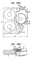
rotating head device 2 is installed will be described with reference to Figs. 13(a) and 13(b). - Fig. 13(a) is a schematic plan view of the magnetic recording and reproducing apparatus in which the rotating head device in Fig. 12 is installed, while Fig. 13(b) is a partially-sectional side view thereof.
- In Figs. 13(a) and 13(b),
numeral 3 designates the magnetic tape, numeral 6 a tape cassette proper, numeral 8 a tape cassette opening, numeral 329 a tape cassette lid, numeral 4 a tape delivery reel, numeral 332 an incoming side tape leading pin, numeral 333 a restraint guide, numeral 334 a tension pin,numerals numerals - The
magnetic tape 3 wound round thedelivery reel 4 is guided by the tape guides mentioned above, is caused to travel by thecapstan 340 and thepinch roller 28, and is taken up round a take-upreel 5. - The
recess 322 of the upper fixedcylinder 35 is set at the position which avoids thetape cassette lid 329 for drawing out the magnetic tape 3 (the front edge C of this cassette lid is indicated by a two-dot chain line), the protrusions of the tape cassette proper 6, etc., thereby permitting thetape cassette opening 8 and therotating head device 2 to overlap, and hence, the horizontal area of the mechanism portion of the magnetic recording and reproducing apparatus with therotating head device 2 installed thereon can be sharply reduced by diminishing a dimension D. - According to the foregoing construction, only the upper fixed cylinder is arranged above the rotary disc which carries the plurality of magnetic heads, so that the recess can be considerably freely formed except in the winding portion of the magnetic tape. Therefore, it is often possible to locate the recess of the upper fixed cylinder in a place which avoids the tape cassette lid protruding to the side of the rotating magnetic heads.
- Thus, the rotating head device can be inserted into the tape cassette opening, and the reduction of the horizontal area of the magnetic recording and reproducing apparatus equipped with the rotating head device becomes possible.
- Moreover, the brushless motor unit and the frequency generator (FG) unit can be magnetically isolated from - the rotary transformer unit by the stator base, and noise ascribable to the leaks of the magnetic fields of the motor unit and the FG unit can be eliminated to prevent the degradations of signal-to-noise ratios attributed to the noise, so that the opposition area of the rotary transformers for signal transmission per channel can be reduced.
- Furthermore, since the rotary transformers are arranged under the rotary disc, a large area enclosed with the inner peripheral surface of the lower fixed cylinder and the outer peripheral surface of the rotary member can be utilized as the opposition plane for the signal transmission.
- In brief, according to this embodiment, it becomes possible to enhance the signal transmission performance of the rotary transformers and to form the recess of the upper fixed cylinder, so that the rotating magnetic heads capable of coping with multi-channeling can be realized in spite of a small diameter. A further effect is that, when the rotating head device is installed on the magnetic recording and reproducing apparatus, the overlap thereof with the tape cassette becomes possible, so the magnetic recording and reproducing apparatus of small horizontal area can be realized.
- Next, other embodiments of the present invention will be described with reference to Fig. 14 and Fig. 15.
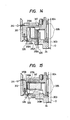
- Fig. 14 is a vertical sectional view of the motor unit and the FG unit of a rotating head device according to another embodiment of the present invention. In the figure, parts with the same symbols as in Fig. 12 are equivalent to those of the embodiment in Fig. 12, and the other parts of the rotating head device not shown are equivalent to the corresponding ones in Fig. 12, so that they shall be omitted from the description.
- In the embodiment of Fig. 14, all of an
FG coil 315A, anFG magnet 316A, amotor magnet 318A and amotor coil 319A are formed cylindrical, and the motor unit and the FG unit are respectively disposed on an outer side and an inner side with respect to the fixedshaft 303. - According to the embodiment of Fig. 14, the same effects as in the foregoing embodiment of Fig. 12 are expected. Besides, since the motor unit is disposed on the outer side, the mean driving radius of the motor enlarges, and the torque constant thereof is readily enlarged, so that reduction in the size of the motor unit can be achieved, and the height of the
motor magnet 318A as well as themotor coil 319A can be diminished. Accordingly, there is the effect peculiar to the present embodiment that the vertical dimension of the rotating head device below thestator base 313 can be lessened. - Fig. 15 is a vertical sectional view of the motor unit and the FG unit of a rotating head device according to still another embodiment of the present invention. In the figure, parts with the same symbols as in Fig. 12 are equivalent to those of the embodiment shown in Fig. 12, and the other parts of the rotating head device not shown are equivalent to the corresponding ones in Fig. 12, so that they shall be omitted from the description.
- In the embodiment of Fig. 15) an
FG coil 315B and anFG magnet 316B are formed cylindrical, while amotor magnet 318B and amotor coil 319B are formed flat, and the FG unit and the motor unit are respectively disposed on an outer side and an inner side with respect to the fixedshaft 303. - According to the embodiment of Fig. 15, the same effects as in the foregoing embodiment of Fig. 12 are expected. Besides, since the FG unit is disposed on the outer side, there is the effect peculiar to the present embodiment that FG signals of high accuracy can be produced and that revolutions of high accuracy can be realized.
- As stated above, according to the embodiments, notwithstanding that cylinders are of small diameter, rotating magnetic heads capable of coping with multi-channeling can be realized, and when the device is installed on a magnetic recording and reproducing apparatus', it is permitted to overlap a tape cassette, and the rotating head device which can realize the magnetic recording and reproducing apparatus of small horizontal area can be provided.
Claims (7)
Applications Claiming Priority (4)
| Application Number | Priority Date | Filing Date | Title |
|---|---|---|---|
| JP61120249A JP2606822B2 (en) | 1986-05-27 | 1986-05-27 | Magnetic recording / reproducing device |
| JP120249/86 | 1986-05-27 | ||
| JP210659/86 | 1986-09-09 | ||
| JP61210659A JPS6366752A (en) | 1986-09-09 | 1986-09-09 | Rotary magnetic head device |
Publications (3)
| Publication Number | Publication Date |
|---|---|
| EP0247442A2 true EP0247442A2 (en) | 1987-12-02 |
| EP0247442A3 EP0247442A3 (en) | 1989-02-22 |
| EP0247442B1 EP0247442B1 (en) | 1993-02-24 |
Family
ID=26457866
Family Applications (1)
| Application Number | Title | Priority Date | Filing Date |
|---|---|---|---|
| EP87106966A Expired - Lifetime EP0247442B1 (en) | 1986-05-27 | 1987-05-14 | Rotating magnetic head device in magnetic recording and reproducing apparatus |
Country Status (4)
| Country | Link |
|---|---|
| US (1) | US4814910A (en) |
| EP (1) | EP0247442B1 (en) |
| KR (1) | KR900007481B1 (en) |
| DE (1) | DE3784269T2 (en) |
Cited By (4)
| Publication number | Priority date | Publication date | Assignee | Title |
|---|---|---|---|---|
| EP0361275A2 (en) * | 1988-09-30 | 1990-04-04 | Hitachi, Ltd. | Tape loading mechanism for magnetic recording and reproducing devices |
| US4949203A (en) * | 1987-03-11 | 1990-08-14 | Pioneer Electronic Corporation | Tape recorder having an improved cassette mounting device |
| EP0422670A2 (en) * | 1989-10-13 | 1991-04-17 | Matsushita Electric Industrial Co., Ltd. | Tape loading device of a video tape recorder |
| EP0531751A2 (en) * | 1991-09-13 | 1993-03-17 | Hitachi, Ltd. | Magnetic recording/reproducing device |
Families Citing this family (9)
| Publication number | Priority date | Publication date | Assignee | Title |
|---|---|---|---|---|
| US5025332A (en) * | 1988-08-30 | 1991-06-18 | Sanyo Electric Co., Ltd. | Recording-reproducing system having movable reel chassis |
| DE3836621A1 (en) * | 1988-10-27 | 1990-05-03 | Thomson Brandt Gmbh | GUIDE FOR A MAGNETIC TAPE |
| JPH02210647A (en) * | 1989-02-10 | 1990-08-22 | Hitachi Ltd | Magnetic recording and reproducing device |
| KR930006211Y1 (en) * | 1990-07-31 | 1993-09-15 | 주식회사 금성사 | Tape transfer guide apparatus of magnetic recording/reproducing apparatus |
| JP2664281B2 (en) * | 1990-11-09 | 1997-10-15 | 株式会社日立製作所 | Magnetic recording / reproducing device |
| JPH0528600A (en) * | 1991-07-18 | 1993-02-05 | Sony Corp | Rotary head drum device and its applied magnetic recording and reproducing device |
| US5430586A (en) * | 1992-08-03 | 1995-07-04 | Koo; Kah O. | Tape extractor and pad lifter for extracting tape from a cassette center well, and related method |
| KR970050266A (en) * | 1995-12-26 | 1997-07-29 | 배순훈 | Head Drum Assembly for Digital VSI |
| US20050244167A1 (en) * | 2004-04-29 | 2005-11-03 | Liew Sanyuan | Signal-to-noise ratio (SNR) value characterization in a data recovery channel |
Citations (4)
| Publication number | Priority date | Publication date | Assignee | Title |
|---|---|---|---|---|
| US3643038A (en) * | 1968-11-09 | 1972-02-15 | Sony Corp | Magnetic recording and/or reproducing system |
| EP0090375A2 (en) * | 1982-03-31 | 1983-10-05 | Hitachi, Ltd. | Rotary magnetic head drum device |
| WO1984003790A1 (en) * | 1983-03-18 | 1984-09-27 | Matsushita Electric Ind Co Ltd | Magnetic recording and reproducing apparatus |
| JPS60187963A (en) * | 1984-03-07 | 1985-09-25 | Hitachi Ltd | Positioning mechanism of tape guide in vtr |
Family Cites Families (3)
| Publication number | Priority date | Publication date | Assignee | Title |
|---|---|---|---|---|
| US4025959A (en) * | 1971-04-05 | 1977-05-24 | Rca Corporation | Recorder-reproducer system |
| US4595961A (en) * | 1982-12-21 | 1986-06-17 | Matsushita Electric Industrial Co., Ltd. | Helical scan type tape recording reproducing apparatus having a part-cylindrical drum |
| NL8403472A (en) * | 1984-11-14 | 1986-06-02 | Philips Nv | MAGNETIC TAPE DEVICE. |
-
1987
- 1987-05-14 EP EP87106966A patent/EP0247442B1/en not_active Expired - Lifetime
- 1987-05-14 DE DE8787106966T patent/DE3784269T2/en not_active Expired - Fee Related
- 1987-05-23 KR KR8705120A patent/KR900007481B1/en not_active IP Right Cessation
- 1987-05-27 US US07/054,864 patent/US4814910A/en not_active Expired - Lifetime
Patent Citations (4)
| Publication number | Priority date | Publication date | Assignee | Title |
|---|---|---|---|---|
| US3643038A (en) * | 1968-11-09 | 1972-02-15 | Sony Corp | Magnetic recording and/or reproducing system |
| EP0090375A2 (en) * | 1982-03-31 | 1983-10-05 | Hitachi, Ltd. | Rotary magnetic head drum device |
| WO1984003790A1 (en) * | 1983-03-18 | 1984-09-27 | Matsushita Electric Ind Co Ltd | Magnetic recording and reproducing apparatus |
| JPS60187963A (en) * | 1984-03-07 | 1985-09-25 | Hitachi Ltd | Positioning mechanism of tape guide in vtr |
Non-Patent Citations (3)
| Title |
|---|
| PATENT ABSTRACTS OF JAPAN * |
| PATENT ABSTRACTS OF JAPAN, vol. 10, no. 41 (P429), 18 February 1986 , & JP-A-60 187963 * |
| PATENT ABSTRACTS OF JAPAN, vol. 9, no. 177 (P-375), 23 July 1985, JP-A-60 050 602 * |
Cited By (8)
| Publication number | Priority date | Publication date | Assignee | Title |
|---|---|---|---|---|
| US4949203A (en) * | 1987-03-11 | 1990-08-14 | Pioneer Electronic Corporation | Tape recorder having an improved cassette mounting device |
| EP0361275A2 (en) * | 1988-09-30 | 1990-04-04 | Hitachi, Ltd. | Tape loading mechanism for magnetic recording and reproducing devices |
| EP0361275A3 (en) * | 1988-09-30 | 1991-02-27 | Hitachi, Ltd. | Tape loading mechanism for magnetic recording and reproducing devices |
| EP0422670A2 (en) * | 1989-10-13 | 1991-04-17 | Matsushita Electric Industrial Co., Ltd. | Tape loading device of a video tape recorder |
| EP0422670A3 (en) * | 1989-10-13 | 1992-02-26 | Matsushita Electric Industrial Co., Ltd. | Tape loading device of a video tape recorder |
| US5204791A (en) * | 1989-10-13 | 1993-04-20 | Matsushita Electric Industrial Co., Ltd. | Tape loading device of a video tape recorder having a linkage driven inclined auxiliary tape guide member |
| EP0531751A2 (en) * | 1991-09-13 | 1993-03-17 | Hitachi, Ltd. | Magnetic recording/reproducing device |
| EP0531751A3 (en) * | 1991-09-13 | 1993-04-28 | Hitachi, Ltd. | Magnetic recording/reproducing device |
Also Published As
| Publication number | Publication date |
|---|---|
| DE3784269D1 (en) | 1993-04-01 |
| DE3784269T2 (en) | 1993-06-09 |
| US4814910A (en) | 1989-03-21 |
| KR870011576A (en) | 1987-12-24 |
| EP0247442B1 (en) | 1993-02-24 |
| KR900007481B1 (en) | 1990-10-10 |
| EP0247442A3 (en) | 1989-02-22 |
Similar Documents
| Publication | Publication Date | Title |
|---|---|---|
| EP0247442B1 (en) | Rotating magnetic head device in magnetic recording and reproducing apparatus | |
| EP0273620B1 (en) | Rotary magnetic head devices | |
| US5438468A (en) | Rotary head drum having reduced exterior dimensions | |
| JPH02281408A (en) | Portable vcr | |
| JP2606822B2 (en) | Magnetic recording / reproducing device | |
| US5016125A (en) | Tape loading mechanism for a magnetic recording/reproducing apparatus | |
| JP2580578B2 (en) | Magnetic recording / reproducing device | |
| JP2927060B2 (en) | Magnetic recording / reproducing device | |
| JPH0450666B2 (en) | ||
| JP3146613B2 (en) | Magnetic recording / reproducing device | |
| JP2848008B2 (en) | Magnetic recording / reproducing device | |
| JP2574760B2 (en) | Tape mounting mechanism | |
| JPH0378151A (en) | Tape guiding mechanism for magnetic recording and reproducing device | |
| JPS6117257A (en) | Magnetic recording and reproducing device | |
| JP3461223B2 (en) | Rotary drum device and recording or reproducing device | |
| JP2570193B2 (en) | Tape recorder | |
| JP3613844B2 (en) | Magnetic recording / reproducing device | |
| JPH05128669A (en) | Magnetic recording and reproducing device | |
| JPS593704A (en) | Magnetic recording and reproducing device | |
| JPH0812730B2 (en) | Magnetic recording / reproducing device | |
| JPH01179265A (en) | Magnetic recording and reproducing device | |
| JPH09212961A (en) | Rotating drum apparatus and recording/reproducing apparatus | |
| JPS6360457B2 (en) | ||
| JPS6224462A (en) | Magnetic recording and reproducing device | |
| JPS583305B2 (en) | Jikiki Rokusai Seisouchi |
Legal Events
| Date | Code | Title | Description |
|---|---|---|---|
| PUAI | Public reference made under article 153(3) epc to a published international application that has entered the european phase |
Free format text: ORIGINAL CODE: 0009012 |
|
| 17P | Request for examination filed |
Effective date: 19870514 |
|
| AK | Designated contracting states |
Kind code of ref document: A2 Designated state(s): DE FR GB |
|
| PUAL | Search report despatched |
Free format text: ORIGINAL CODE: 0009013 |
|
| AK | Designated contracting states |
Kind code of ref document: A3 Designated state(s): DE FR GB |
|
| 17Q | First examination report despatched |
Effective date: 19901120 |
|
| GRAA | (expected) grant |
Free format text: ORIGINAL CODE: 0009210 |
|
| AK | Designated contracting states |
Kind code of ref document: B1 Designated state(s): DE FR GB |
|
| REF | Corresponds to: |
Ref document number: 3784269 Country of ref document: DE Date of ref document: 19930401 |
|
| ET | Fr: translation filed | ||
| PLBE | No opposition filed within time limit |
Free format text: ORIGINAL CODE: 0009261 |
|
| STAA | Information on the status of an ep patent application or granted ep patent |
Free format text: STATUS: NO OPPOSITION FILED WITHIN TIME LIMIT |
|
| 26N | No opposition filed | ||
| PGFP | Annual fee paid to national office [announced via postgrant information from national office to epo] |
Ref country code: FR Payment date: 19980415 Year of fee payment: 12 |
|
| PGFP | Annual fee paid to national office [announced via postgrant information from national office to epo] |
Ref country code: GB Payment date: 19980501 Year of fee payment: 12 |
|
| PGFP | Annual fee paid to national office [announced via postgrant information from national office to epo] |
Ref country code: DE Payment date: 19980629 Year of fee payment: 12 |
|
| PG25 | Lapsed in a contracting state [announced via postgrant information from national office to epo] |
Ref country code: GB Free format text: LAPSE BECAUSE OF NON-PAYMENT OF DUE FEES Effective date: 19990514 |
|
| GBPC | Gb: european patent ceased through non-payment of renewal fee |
Effective date: 19990514 |
|
| PG25 | Lapsed in a contracting state [announced via postgrant information from national office to epo] |
Ref country code: FR Free format text: LAPSE BECAUSE OF NON-PAYMENT OF DUE FEES Effective date: 20000131 |
|
| PG25 | Lapsed in a contracting state [announced via postgrant information from national office to epo] |
Ref country code: DE Free format text: LAPSE BECAUSE OF NON-PAYMENT OF DUE FEES Effective date: 20000301 |
|
| REG | Reference to a national code |
Ref country code: FR Ref legal event code: ST |