EP0247330A2 - Radzierkappe, insbesondere für Kraftfahrzeugräder - Google Patents
Radzierkappe, insbesondere für Kraftfahrzeugräder Download PDFInfo
- Publication number
- EP0247330A2 EP0247330A2 EP87104892A EP87104892A EP0247330A2 EP 0247330 A2 EP0247330 A2 EP 0247330A2 EP 87104892 A EP87104892 A EP 87104892A EP 87104892 A EP87104892 A EP 87104892A EP 0247330 A2 EP0247330 A2 EP 0247330A2
- Authority
- EP
- European Patent Office
- Prior art keywords
- wheel hub
- hub cover
- automotive vehicle
- elements
- vehicle wheels
- Prior art date
- Legal status (The legal status is an assumption and is not a legal conclusion. Google has not performed a legal analysis and makes no representation as to the accuracy of the status listed.)
- Withdrawn
Links
- 230000008878 coupling Effects 0.000 claims abstract description 18
- 238000010168 coupling process Methods 0.000 claims abstract description 18
- 238000005859 coupling reaction Methods 0.000 claims abstract description 18
- 230000008602 contraction Effects 0.000 claims description 3
- 239000000463 material Substances 0.000 description 5
- 229910052751 metal Inorganic materials 0.000 description 3
- 239000002184 metal Substances 0.000 description 2
Images
Classifications
-
- B—PERFORMING OPERATIONS; TRANSPORTING
- B60—VEHICLES IN GENERAL
- B60B—VEHICLE WHEELS; CASTORS; AXLES FOR WHEELS OR CASTORS; INCREASING WHEEL ADHESION
- B60B7/00—Wheel cover discs, rings, or the like, for ornamenting, protecting, venting, or obscuring, wholly or in part, the wheel body, rim, hub, or tyre sidewall, e.g. wheel cover discs, wheel cover discs with cooling fins
- B60B7/06—Fastening arrangements therefor
- B60B7/12—Fastening arrangements therefor comprising an annular spring or gripping element mounted on the cover
Definitions
- the present invention relates to a wheel hub cover,particularly for automotive vehicle wheels.
- wheel hub covers are currently available on the market which may be applied to the central outer part of a wheel hub, and which are substantially composed of a central portion, that can be provided with any desired aesthetic pattern.
- the central part connects to a lateral border or band having a cylindrical shape and radial coupling projections which allow one to effect the snap-together coupling with a groove usually provided on the wheel hub.
- the aim proposed by the present invention is indeed to eliminate the above described disadvantages by providing a new type of wheel hub cover for automotive vehicle wheels which allows the possibility of always effecting a stable snap-together coupling between the wheel hub cover and the wheel hub without the danger of a reduction in the outward elastic radial thrust exerted by the snap-together connecting elements.
- a particular object of the invention is to provide a wheel hub cover which allows the possibility of being applied very quickly and simply to the wheel hub itself, furthermore having the advantage of preventing the rotation of the wheel hub cover with respect to the wheel hub.
- Still another object of the present invention is to provide a wheel hub cover which is very quick and simple to assemble and which furthermore is capable of giving the greatest assurances of reliability and safety in use.
- a not least object of the present invention is to provide a structure of a wheel hub cover which can be easily manufactured from elements and materials commonly available on the market and which is furthermore advantageous from a merely economical point of view.
- a wheel hub cover particularly for automotive vehicle wheels comprising a central portion,wherefrom extends an annular band, arranged coaxially with respect to said central portion, characterized in that it comprises tooth-like elements projecting radially from said annular band and adapted for snap-together coupling with a groove provided on the wheel hub, an annular element being furthermore provided which engages with said tooth-like elements to push or thrust them elastically outwards.
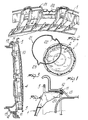
- a wheel hub cover particularly for automotive vehicle wheels, according to the invention, which is generally indicated with the reference numeral 1, comprises a central portion 2 which is substantially circular and may be provided with any graphic representation or configuration whatever, such as to alter the aesthetic appearance of the outer surface of the central portion 2 which will be in view.
- annular band 4 extends which is advantageously separated from the central part 2 by an outer annular border, indicated with the reference numeral 5.
- the radial projection 11 is inserted, in a snap-together manner into a groove 12 which is usually provided on the hub, generally indicated by the reference numeral 13.
- tooth-like elements 10 in their inner part, define a recess 20 in which an annular element 21 can be accommodated, which has the function of exerting an elastic radial thrust towards the outside, so as to elastically push the teeth 10, at the projection 11, to make the coupling between the wheel hub cover 1 and the groove 12 more stable and safe.
- a bend or shoulder 22 is provided on the annular extension of the annular element 21; the bend 22 is also intended to allow the avoidance of the region affected by the valve of the tyre applied to the wheel hub cover.
- a second bend or shoulder 23 is provided which is advantageously arranged diametrically opposite with respect to the first bend 22.
- the annular element 21 may advantageously be manufactured in metal rod, bent to assume the desired shape.
- annular element 21 is very important, since, in engaging with the tooth-like elements 10, it pushes the same outwards with a relatively strong elastic biasing action so as to always afford a precise and stable coupling.
- the invention achieves the intended aims and in particular the fact is stressed that the elasticity of the snap-together coupling is not assigned exclusively to the intrinsic elasticity of the plastic material used to provide the wheel hub cover, as is found in the solutions of the prior art, but to the presence of the annular element, which, by cooperating with the tooth-like elements which may be advantageously provided monolithically or enbloc with the wheel hub cover, is capable of imparting a high radial thrust which always keeps the coupling stable and safe.
- the contact between the wheel hub cover and the wheel hub only occurs at the projections 11 of the tooth-like elements, i.e. there is a coupling between the material, for example plastic, composing the wheel hub cover, and the material such as metal composing the wheel hub, which prevents noise and vibrations, even though it may have an elastic thrust imparted by a metallic element, i.e. by a metallic annular element 21.
- the materials employed may be any according to the requirements.
Landscapes
- Engineering & Computer Science (AREA)
- Mechanical Engineering (AREA)
- Snaps, Bayonet Connections, Set Pins, And Snap Rings (AREA)
Applications Claiming Priority (2)
| Application Number | Priority Date | Filing Date | Title |
|---|---|---|---|
| IT2198486 | 1986-05-26 | ||
| IT2198486U IT209397Z2 (it) | 1986-05-26 | 1986-05-26 | Struttura di copricerchione partivolarmente per ruote di autoveicoli. |
Publications (2)
| Publication Number | Publication Date |
|---|---|
| EP0247330A2 true EP0247330A2 (de) | 1987-12-02 |
| EP0247330A3 EP0247330A3 (de) | 1989-01-11 |
Family
ID=11189784
Family Applications (1)
| Application Number | Title | Priority Date | Filing Date |
|---|---|---|---|
| EP87104892A Withdrawn EP0247330A3 (de) | 1986-05-26 | 1987-04-02 | Radzierkappe, insbesondere für Kraftfahrzeugräder |
Country Status (2)
| Country | Link |
|---|---|
| EP (1) | EP0247330A3 (de) |
| IT (1) | IT209397Z2 (de) |
Cited By (5)
| Publication number | Priority date | Publication date | Assignee | Title |
|---|---|---|---|---|
| EP0300333A1 (de) * | 1987-07-13 | 1989-01-25 | Kanto Seiki Co., Ltd. | Kunststoffradzierblende mit Befestigungsvorrichtung |
| US4929031A (en) * | 1988-11-21 | 1990-05-29 | Shenq Gwo Liou | Structure of hub cap for car wheel |
| GB2259891A (en) * | 1991-09-18 | 1993-03-31 | Crimson Company Limited | Insert for automotive wheel |
| EP0629517A1 (de) * | 1993-06-18 | 1994-12-21 | United Wheelcovers Aktiebolag | Montagevorrichtung für Radkappen an Felgen von Fahrzeugrädern |
| EP1992500A1 (de) * | 2007-05-15 | 2008-11-19 | Lupini Targhe S.p.A. | Radblende für ein Kraftfahrzeug |
Family Cites Families (3)
| Publication number | Priority date | Publication date | Assignee | Title |
|---|---|---|---|---|
| DE2937083C2 (de) * | 1979-09-13 | 1984-06-14 | Daimler-Benz Ag, 7000 Stuttgart | Radblende, insbesondere für die Räder von Personenkraftwagen |
| DE2943139A1 (de) * | 1979-10-25 | 1981-05-07 | Daimler-Benz Ag, 7000 Stuttgart | Radblende, insbesondere fuer raeder von personenkraftwagen |
| US4596425A (en) * | 1984-04-24 | 1986-06-24 | Hung Rong Tsan | Plastic wheel cover using retaining ring |
-
1986
- 1986-05-26 IT IT2198486U patent/IT209397Z2/it active
-
1987
- 1987-04-02 EP EP87104892A patent/EP0247330A3/de not_active Withdrawn
Cited By (8)
| Publication number | Priority date | Publication date | Assignee | Title |
|---|---|---|---|---|
| EP0300333A1 (de) * | 1987-07-13 | 1989-01-25 | Kanto Seiki Co., Ltd. | Kunststoffradzierblende mit Befestigungsvorrichtung |
| US4917441A (en) * | 1987-07-13 | 1990-04-17 | Kanto Seiki Co., Ltd. | Plastic wheel cover with fastening device |
| US4929031A (en) * | 1988-11-21 | 1990-05-29 | Shenq Gwo Liou | Structure of hub cap for car wheel |
| GB2259891A (en) * | 1991-09-18 | 1993-03-31 | Crimson Company Limited | Insert for automotive wheel |
| AU642300B2 (en) * | 1991-09-18 | 1993-10-14 | Crimson Company Limited | An insert and/or ornament for automotive wheel |
| GB2259891B (en) * | 1991-09-18 | 1995-03-22 | Crimson Company Limited | Automotive wheel |
| EP0629517A1 (de) * | 1993-06-18 | 1994-12-21 | United Wheelcovers Aktiebolag | Montagevorrichtung für Radkappen an Felgen von Fahrzeugrädern |
| EP1992500A1 (de) * | 2007-05-15 | 2008-11-19 | Lupini Targhe S.p.A. | Radblende für ein Kraftfahrzeug |
Also Published As
| Publication number | Publication date |
|---|---|
| IT8621984V0 (it) | 1986-05-26 |
| IT209397Z2 (it) | 1988-10-05 |
| EP0247330A3 (de) | 1989-01-11 |
Similar Documents
| Publication | Publication Date | Title |
|---|---|---|
| US5193917A (en) | Rolling bearings for steering columns | |
| US4290166A (en) | Self-aligning twin-wheeled caster | |
| EP0387967B1 (de) | Rohrschelle | |
| KR940015324A (ko) | 기계요소의 축에의 부착구조 | |
| EP0247330A2 (de) | Radzierkappe, insbesondere für Kraftfahrzeugräder | |
| JP4740592B2 (ja) | 流体ディスペンサ部材用の留め具要素、および、そうした留め具要素を有する流体ディスペンサ部材 | |
| US4911269A (en) | Twin wheel caster with integral brake assembly | |
| KR900702601A (ko) | 로크부착소켓 | |
| US3998494A (en) | Wheel and grease cap assembly | |
| US2020885A (en) | Wheel cover | |
| US3912176A (en) | Manually operated kitchen grater | |
| US3028736A (en) | Ring guard having lapped resilient tongues | |
| US2993250A (en) | Fabric faced button | |
| EP0199344B1 (de) | Längliche bajonettverschlussartige Befestigungsvorrichtung für Steuer- und Signaleinheiten | |
| US3857300A (en) | Folding handwheel handle | |
| US3467476A (en) | Writing instrument | |
| US4149754A (en) | Wheel trim retention | |
| US2569483A (en) | Wheel cover | |
| US2733104A (en) | Wheel structure | |
| US2855229A (en) | Connection for indicator dials or the like | |
| US3428344A (en) | Fastening device | |
| US4183587A (en) | Wheel and hubcap assembly | |
| US2193106A (en) | Ornamental member fastening means | |
| US4778161A (en) | Device for securing a spring on a rod | |
| US4518131A (en) | Inertial element for winding the safety belt of a motor vehicle |
Legal Events
| Date | Code | Title | Description |
|---|---|---|---|
| PUAI | Public reference made under article 153(3) epc to a published international application that has entered the european phase |
Free format text: ORIGINAL CODE: 0009012 |
|
| AK | Designated contracting states |
Kind code of ref document: A2 Designated state(s): AT BE CH DE ES FR GB GR LI LU NL SE |
|
| PUAL | Search report despatched |
Free format text: ORIGINAL CODE: 0009013 |
|
| AK | Designated contracting states |
Kind code of ref document: A3 Designated state(s): AT BE CH DE ES FR GB GR LI LU NL SE |
|
| 17P | Request for examination filed |
Effective date: 19890609 |
|
| 17Q | First examination report despatched |
Effective date: 19900206 |
|
| STAA | Information on the status of an ep patent application or granted ep patent |
Free format text: STATUS: THE APPLICATION IS DEEMED TO BE WITHDRAWN |
|
| 18D | Application deemed to be withdrawn |
Effective date: 19900619 |
|
| RIN1 | Information on inventor provided before grant (corrected) |
Inventor name: BELLU' MARIO |