EP0247276A2 - Vergasersystem für eine Brennkraftmaschine - Google Patents
Vergasersystem für eine Brennkraftmaschine Download PDFInfo
- Publication number
- EP0247276A2 EP0247276A2 EP87101226A EP87101226A EP0247276A2 EP 0247276 A2 EP0247276 A2 EP 0247276A2 EP 87101226 A EP87101226 A EP 87101226A EP 87101226 A EP87101226 A EP 87101226A EP 0247276 A2 EP0247276 A2 EP 0247276A2
- Authority
- EP
- European Patent Office
- Prior art keywords
- fuel
- primer
- pump
- chamber
- metering chamber
- Prior art date
- Legal status (The legal status is an assumption and is not a legal conclusion. Google has not performed a legal analysis and makes no representation as to the accuracy of the status listed.)
- Granted
Links
- 238000002485 combustion reaction Methods 0.000 title claims abstract description 19
- 239000000446 fuel Substances 0.000 claims abstract description 183
- 230000037452 priming Effects 0.000 claims abstract description 52
- 238000005336 cracking Methods 0.000 claims description 28
- 230000003068 static effect Effects 0.000 claims description 9
- 238000004891 communication Methods 0.000 claims description 3
- 239000000356 contaminant Substances 0.000 claims description 3
- 230000004044 response Effects 0.000 claims 2
- 239000007788 liquid Substances 0.000 abstract description 7
- 238000005086 pumping Methods 0.000 abstract description 4
- 238000010926 purge Methods 0.000 abstract 1
- 230000006698 induction Effects 0.000 description 11
- 239000000203 mixture Substances 0.000 description 9
- 238000012546 transfer Methods 0.000 description 6
- 239000002828 fuel tank Substances 0.000 description 5
- 238000000034 method Methods 0.000 description 4
- 239000012528 membrane Substances 0.000 description 3
- 229910000831 Steel Inorganic materials 0.000 description 2
- 230000000994 depressogenic effect Effects 0.000 description 2
- 238000013461 design Methods 0.000 description 2
- 230000005484 gravity Effects 0.000 description 2
- 239000010959 steel Substances 0.000 description 2
- 230000000903 blocking effect Effects 0.000 description 1
- 238000010276 construction Methods 0.000 description 1
- 238000010586 diagram Methods 0.000 description 1
- 238000006073 displacement reaction Methods 0.000 description 1
- 230000001788 irregular Effects 0.000 description 1
- 230000007257 malfunction Effects 0.000 description 1
- 239000000463 material Substances 0.000 description 1
- 239000004033 plastic Substances 0.000 description 1
- 239000012780 transparent material Substances 0.000 description 1
- 238000013022 venting Methods 0.000 description 1
Images


Classifications
-
- F—MECHANICAL ENGINEERING; LIGHTING; HEATING; WEAPONS; BLASTING
- F02—COMBUSTION ENGINES; HOT-GAS OR COMBUSTION-PRODUCT ENGINE PLANTS
- F02M—SUPPLYING COMBUSTION ENGINES IN GENERAL WITH COMBUSTIBLE MIXTURES OR CONSTITUENTS THEREOF
- F02M17/00—Carburettors having pertinent characteristics not provided for in, or of interest apart from, the apparatus of preceding main groups F02M1/00 - F02M15/00
- F02M17/02—Floatless carburettors
- F02M17/04—Floatless carburettors having fuel inlet valve controlled by diaphragm
-
- F—MECHANICAL ENGINEERING; LIGHTING; HEATING; WEAPONS; BLASTING
- F02—COMBUSTION ENGINES; HOT-GAS OR COMBUSTION-PRODUCT ENGINE PLANTS
- F02M—SUPPLYING COMBUSTION ENGINES IN GENERAL WITH COMBUSTIBLE MIXTURES OR CONSTITUENTS THEREOF
- F02M1/00—Carburettors with means for facilitating engine's starting or its idling below operational temperatures
- F02M1/16—Other means for enriching fuel-air mixture during starting; Priming cups; using different fuels for starting and normal operation
-
- Y—GENERAL TAGGING OF NEW TECHNOLOGICAL DEVELOPMENTS; GENERAL TAGGING OF CROSS-SECTIONAL TECHNOLOGIES SPANNING OVER SEVERAL SECTIONS OF THE IPC; TECHNICAL SUBJECTS COVERED BY FORMER USPC CROSS-REFERENCE ART COLLECTIONS [XRACs] AND DIGESTS
- Y10—TECHNICAL SUBJECTS COVERED BY FORMER USPC
- Y10S—TECHNICAL SUBJECTS COVERED BY FORMER USPC CROSS-REFERENCE ART COLLECTIONS [XRACs] AND DIGESTS
- Y10S261/00—Gas and liquid contact apparatus
- Y10S261/08—Carburetor primers
-
- Y—GENERAL TAGGING OF NEW TECHNOLOGICAL DEVELOPMENTS; GENERAL TAGGING OF CROSS-SECTIONAL TECHNOLOGIES SPANNING OVER SEVERAL SECTIONS OF THE IPC; TECHNICAL SUBJECTS COVERED BY FORMER USPC CROSS-REFERENCE ART COLLECTIONS [XRACs] AND DIGESTS
- Y10—TECHNICAL SUBJECTS COVERED BY FORMER USPC
- Y10S—TECHNICAL SUBJECTS COVERED BY FORMER USPC CROSS-REFERENCE ART COLLECTIONS [XRACs] AND DIGESTS
- Y10S261/00—Gas and liquid contact apparatus
- Y10S261/68—Diaphragm-controlled inlet valve
Definitions
- the invention relates to a priming system for an internal combustion engine and a method of priming an internal combustion engine in order to facilitate easy starting of the engine.
- the inlet needle valve opening is minimal due to such a small travel of the needle and as soon as the pressure drops in the metering chamber, the metering diaphragm retracts to its static position causing the inlet valve to close and shut off fuel delivery to the metering chamber.
- the fuel supply tank In order for fuel to enter the metering chamber while the inlet valve is open, the fuel supply tank must be sufficiently above the carburetor for gravity to force feed the chamber. As the primer bulb is released and resumes its original shape, the atmosphere vent is uncovered and pressure is reduced at the diaphragm and in the metering chamber. This pressure reduction can aid in drawing fuel into the metering chamber, but once the diaphragm has retracted, the metering lever, following the diaphragm causes the inlet needle valve to fully close and only a small quantity of fuel will enter the chamber.
- This type of priming system often requires as many as twenty actuations of the manual primer to prime a dry fuel system from the tank to the carburetor, and often another six to eight primes will be required to supply enough fuel to the induction system for a cool weather engine start.
- This system is also ineffective when utilized with a closed fuel system wherein the fuel tank is under vacuum such as with a vacuum opening tank vent and is inoperative when the fuel tank is below the carburetor.
- the present invention in one form thereof, provides a priming system for an internal combustion engine wherein the primer bulb line, the inlet passage and the primer passage are all connected to the outlet side of the fuel pump outlet check valve.
- the priming line is connected through a check valve to the priming orifice and the inlet or metering valve of the diaphragm carburetor is connected to the inlet line.
- the cracking pressure of the primer check valve is substantially lower than the cracking pressure of the inlet valve so that actuation of the primer bulb will force fuel through the primer check valve and into the induction system of the engine.
- the primer bulb As the primer bulb is operated, air is first purged from the fuel line, fuel pump, primer bulb line and primer passageway, and'subsequent actuations of the primer bulb will fill the primer bulb, fuel pump and primer line completely with fuel, at which point subsequent actuations will force liquid fuel into the throat of the carburetor.
- the inlet valve opens and the fuel pump, which is preferably of the pulse-type, is full of fuel and will immediately begin to pump fuel into the metering chamber, which fuel is then drawn into the engine induction system. Because the priming fuel bypasses the metering chamber, priming fuel can be introduced into the engine induction system with fewer actuations of the primer bulb. Furthermore, the cracking pressure of the primer check valve can be made quite low thereby enabling easier priming.
- priming is accomplished through the metering chamber by means of a priming passage between the outlet side of the primer pump, through a priming check valve and into the metering chamber parallel to the inlet passage for the metering chamber.
- a priming passage between the outlet side of the primer pump, through a priming check valve and into the metering chamber parallel to the inlet passage for the metering chamber.
- the diaphragm which is convoluted, will be stretched beyond its normal rest position, and although it will rebound, it will not rebound to its original static position.
- the metering chamber volume is left increased beyond the normal static or engine running volume, which will supply a rich fuel-air mixture on initial starting of the engine.
- the additional charge of fuel in the metering chamber will be depleted and normal, leaner fuel mixture conditions will prevail.
- the engine can also be primed after starting by manually pumping excess fuel into the metering chamber, which will again charge the metering chamber beyond its normal quantity of fuel and produce a richer fuel-air mixture.
- the present invention in one form thereof, provides a primer system for an internal combustion engine and a method of priming an internal combustion engine wherein the entire liquid fuel system of the engine from the fuel supply tank to and including the carburetor is filled during priming in order to facilitate easy starting of the engine.
- the priming system also provides for the delivery of liquid fuel directly into the carburetor induction system for subsequent intake into the engine combustion chamber for the purpose of providing a starting prime charge to facilitate easy starting of the engine.
- the priming system also provides a manually actuatable means of delivering a quantity of liquid fuel directly into the induction system for subsequent intake into the engine combustion chamber for the purpose of providing an enriched fuel-air mixture, as required, in order to sustain initial cold engine operation and eliminate stall outs. Further, the priming system and method for priming provides an means of delivering a precise predetermined quantity of liquid fuel into the induction system for subsequent intake into the engine combustion chamber for the purpose of providing an enriched fuel-air mixture in order to sustain initial cold engine operation and eliminate stall outs.
- the priming system is designed so that there is flexibility in the amount of fuel which can be delivered to the engine induction system for starting with a minimal number of manual primer actuations. With the present priming system the operator can, in many cases, fill the entire fuel system and prime the engine for starting in two to four actuations of the manual primer actuator.
- the present priming system also does not require that the fuel tank be mounted above the carburetor since a gravity feed fuel system is not required. Consequently, the fuel tank can be mounted below the engine, if desired from a design standpoint, with no loss in priming efficiency.
- the priming system can also be utilized with a fuel tank having a normally sealed design with venting to the atmosphere achieved by a vacuum opening vent. Further, a vent hole is not required in the manual primer actuator so moisture and dirt contaminants will not enter the system through the hole and cause carburetor prime system malfunctions.
- the manual primer actuator volume, primer line volume, primer valve cracking pressure and the primer feed orifice size can all be varied so as to achieve a desired quantity and quality of prime charge. 7
- the invention in one form thereof, is a carburetion system for an internal combustion engine comprising a diaphragm carburetor including a carburetor body, an air-fuel passage in the carburetor body adapted to communicate with an engine combustion chamber, a fuel metering chamber in the carburetor body in communication with the air-fuel passage and a fuel pump including a fuel chamber in the carburetor body.
- the metering chamber communicates with the fuel pump chamber and air-fuel passage.
- the carburetion system includes a manually actuatable primer pump including a variable volume chamber, a fuel pump outlet check valve having an inlet side connected to the fuel pump and an outlet side connected to the primer pump chamber, a priming passageway in the carburetor body connected to the air-fuel passage and a primer check valve having an inlet connected to the primer pump chamber and an outlet connected to the priming passageway.
- An inlet passageway in the carburetor body communicates between the outlet side of the fuel pump outlet check valve and the metering chamber.
- the carburetion system in accordance with another form of the invention, comprises a diaphragm carburetor including a carburetor body, an air-fuel passage in the carburetor body adapted to communicate with an engine combustion chamber, a fuel metering chamber in the carburetor body communicating with an air-fuel passage through an orifice and a fuel pump including a fuel chamber in the carburetor body.
- the carburetor system includes a manually actuatable primer pump including a variable volume chamber, a fuel pump outlet check valve having an inlet side connected to the fuel pump and an outlet side communicating with the primer pump chamber, and a primer check valve having an inlet connected to the outlet side of the fuel pump check valve and an outlet side connected to the metering chamber, the primer check valve having a predetermined cracking pressure.
- a diaphragm operated inlet valve having an inlet connected to the outlet side of the fuel pump and having an outlet connected to the metering chamber has a cracking pressure whereby the inlet valve opens when the diaphragm reacts to a pressure drop in the metering chamber pushing against the metering lever.
- the inlet valve static cracking pressure being higher than the primer valve cracking pressure.
- the primer pump is operative for pumping fuel through the primer check valve and metering chamber into the air-fuel passage.
- fuel supply tank 10 is connected by fuel line 12 and inlet check valve 14 to fuel pump 16, which is of the pulse-type comprising a fuel chamber 18 and a pulse chamber 20, the latter connected by a passage 22 to the engine crankcase 24.
- fuel pump 16 which is of the pulse-type comprising a fuel chamber 18 and a pulse chamber 20, the latter connected by a passage 22 to the engine crankcase 24.
- pulses developed in the crankcase of the engine intermittently pressurize pulse chamber 20, which causes diaphragm 26 to move relative to fuel chamber 18 thereby pumping fuel from fuel supply tank 10 out through outlet check valve 28.
- Primer pump 30 comprises a bulb, bellows or other actuator 32 comprising a variable volume chamber 34, and is connected to surge chamber 36 by tubing 38, passage 40, passage 42 and passage 120.
- Inlet passage 44 connects surge chamber 36 to metering chamber 46 through inlet valve 48.
- Valve 48 opens and closes under the control of metering lever 50 to meter fuel into metering chamber 46 depending on the pressure and fuel conditions within metering chamber 46.
- Metering lever 50 is supported on pivot 52 and is actuated by the movement of diaphragm 54 in a manner well known in the art.
- the lower chamber 56 of metering chamber 46 is vented to the atmosphere through an opening 58.
- Metering spring 60 biases inlet valve 48 closed against the action of diaphragm 54.
- Idle port 62 which opens into the throat portion 64 of carburetor 66, is connected to chamber 46 through idle adjustment valve 68.
- Main fuel port 70 opens into the venturi portion 72 of carburetor throat 64 and is connected to metering chamber 46 through main check valve 132 and adjustment valve 74.
- Carburetor throat 64 is part of the induction system for the internal combustion engine (not shown) to which the fuel pump-carburetor 66 is connected. When a vacuum is drawn on carburetor throat 64 by the engine, fuel is drawn into throat 64 through main and idle ports 70 and 62. Also opening into carburetor throat 64 is priming orifice 76, which is connected by passageway 78 and priming check valve 80 to passages 82 and 42, the latter connected to passageway 40.
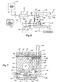
- carburetor-fuel pump 66 is shown in greater detail. It comprises a carburetor body 84, a cover portion 86 and a gasket 88 and resilient diaphragm membrane 90 sandwiched between cover 86 and l body 84.
- Primer tubing fitting 92 connects to passageway 40, which is connected to passage 42, which is connected to passage 120, the latter being connected to surge chamber 36.
- Priming valve 80 comprises valve seat 94 disposed within cylindrical recess 96, valve 98 and valve spring 100, the latter being received within cylindrical recess 102.
- Spring 100 biases valve 98 into seating relationship with valve seat 94, thereby blocking the flow of fuel below a predetermined cracking pressure.
- the preset cracking pressure of priming valve 80 is reached, which in this case is approximately 6 psi, then valve 80 opens and fuel flows through priming passageway 78 and port 76 into carburetor throat 64.
- Figs. 2 and 5 illustrate the connection between passage 40 and valve 80.
- Fuel pump 16 comprises chambers 18 and 20 formed in cover 86 and carburetor body 84, respectively, and the chambers are separated from each other by portion 106 of flexible membrane 90, which forms a diaphragm between chambers 18 and 20.
- Passage 22 from the engine crankcase (Figs. 2 and 3) communicates with pulse chamber 18 through passages 108 and 110.
- fuel is drawn into fuel chamber 20 of fuel pump-16 through fuel line fitting 112, passage 114, inlet check valve 14 and through transfer passage 116.
- Fuel is pumped from fuel chamber 20 through outlet check valve 28 (Fig. 5) through transfer passage 118 and passage 120 to surge chamber 36.
- valve 48 which comprises valve body 124 received in valve recess 128 and preferably having an irregular cross-section, such as hexagonal.
- the upper portion 126 of valve 124 seats against shoulder 128 of inlet passage 44 when biased against it by spring 60 and metering arm 50, the latter being connected to valve body 48 by means of groove 130.
- Diaphragm 54 is sandwiched between carburetor body 84 and metering chamber cover 132 together with a gasket 134.
- Spring 60 biases metering lever 50 in a counterclockwise direction as indicated in Fig. 2 thereby seating valve 48 and preventing the flow of fuel from passage 44 into metering chamber 46.
- the chamber 56 formed between diaphragm 54 and cover 132 is at atmospheric pressure because of vent opening 58.
- Metering chamber 46 communicates with carburetor throat 64 formed in carburetor body 84 through main mixture orifice 74, check valve 138 and main fuel port 70.
- Spring 60 normally closes valve 48, but when vacuum is created within carburetor throat 64 during starting and running conditions of the engine, the reduced pressure within chamber 46 will cause diaphragm 54 to move upwardly thereby rotating metering lever 50 clockwise and opening valve 48.
- diaphragm 54 moves in a downward direction as viewed in Fig. 2, then valve 48 will be closed.
- valve 48 The tension of spring 60 is such that the static cracking pressure of valve 48, that is, the pressure within inlet passage 44 acting on the upper portion 126 of valve body 124, exceeds 28 psi, for example, valve 48 will open. Since the typical output pressure of fuel pump 16 is approximately 2-3 psi, valve 48 will be opened only through the action of diaphragm 54 and not by normal pressure within inlet passage 44. As mentioned earlier, the cracking pressure of primer check valve 80 is approximately 6 psi.
- Figs. 1-5 operates as follows. With the carburetor-fuel pump system 66 completely dry, as primer bulb 32 is depressed, air in primer bulb 32 is forced out through tube 38, passage 40, passage 42 and transfer passage 118, thereby closing fuel pump outlet check valve 28. When the pressure within the expansible chamber 34 reaches a predetermined pressure, such as 6 psi, which occurs very soon after initial depression of the manual primer bulb 32 begins, primer check valve 80 opens and air flows through primer passageway 70 into carburetor throat 64. Primer feed orifice 76 preferably has a diameter of approximately .025 inches.
- primer bulb 32 When primer bulb 32 is released, expansible chamber 34 expands to its original volume, thereby producing a negative pressure in the prime system and placing a negative pressure at fuel pump outlet check valve 28. This opens the inlet valve 14 and outlet valve 28 of fuel pump 16 and closes primer check valve 80, thereby drawing fuel into fuel pump 16 from fuel supply tank 10.
- fuel line 12 fuel pump 16, primer bulb 32, primer line 38 and passage 114, transfer passage 116, passage 40, passage 42, chamber 36, passage 120 and transfer passage 118 will be purged of air and filled with liquid fuel.
- subsequent actuations of primer bulb 32 will force fuel through priming passageway 78 and priming port 76 into carburetor throat 64.
- the prime fuel is now available to be inducted into the combustion chamber of the engine as the engine is cranked. It should be noted that priming can be accomplished even after the engine is running.
- Figs. 6, 7 and 8 an alternative embodiment of the present invention is shown, wherein corresponding elements to those of the embodiment of Figs. 1-5 are denoted by primed reference numerals.
- primer check valve 80' is connected to metering chamber 46' rather than being connected directly to carburetor throat 64', as was the case in the earlier discussed embodiment.
- priming passageway 140 connects chamber 102' of primer check valve 80' to metering chamber 46'.
- Fig. 8 illustrates primer bulb 30', which is identical in both embodiments, and which comprises a primer cup 142 including an annular groove 144 in which is received the flange portion 146 of resilient primer bulb 32'. Annular retainer clip 148 frictionally secures bulb 32' in place.
- Tubing 38' which may have a length of 4-6 inches, for example, connects the stepped portion 150 of primer 30' to fitting 112' on carburetor 66'.
- primer bulb 32' and tubing 38' are made of a transparent material that the operator can visually determine when the priming system has been filled with fuel.
- Figs. 6, 7 and 8 operates as follows.
- air therein is forced outwardly through tubing 38' into passage 40 and 42' and transfer passage 118, thereby closing fuel pump outlet check valve 28'.
- primer valve 80' opens and air begins to flow through primer feed orifice into metering chamber 46'.
- the metering chamber volume increases as metering diaphragm 54' expands outward while the remainder of the air charge is injected into the carburetor throat through the main and idle feed orifices 70' and 62'.
- Air will continue to flow until the pressure in the prime system drops below 6 psi and primer valve 80' closes, or until primer bulb 32' is released.
- primer valve 80' closes, or until primer bulb 32' is released.
- the manual primer bulb 32' expands to its original shape causing negative pressure, which draws on tubing 38' thereby creating a negative pressure in fuel pump 16'. This opens inlet valve 14' and outlet valve 28' and draws fuel from fuel supply tank 10'.
- diaphragm 54' will not completely resume its original static position. Fuel will feed until pressure in metering chamber 46' is depleted and diaphragm 54' is unable to rebound against the weight of the remaining fuel, at which point the metering chamber volume is increased beyond its static or engine running volume due to the excess fuel therein. This process is repeated on each depression of primer 30' thereby leaving the metering chamber “charged” for starting. Continued depression of primer 30' will force excess fuel from metering chamber 46 through main and idle feed orifices 70' and 62' so that the amount of prime charge introduced into carburetor 64' is totally under the control of the operator.
- primer check valve 80 can take the form of a ball made of steel, plastic or other rigid material again seating against a rubber seat.
- gasket 88 could be provided with a steel eyelet 154 disposed within an opening 156 in gasket 88', and then hinging a portion of membrane 90' therebelow so that it opens and closes against the eyelet 154.
- a return spring 158 would maintain the valve flap 160 in seating engagement with the eyelet 154 until suitable cracking pressure has been developed in chamber 34.
Landscapes
- Engineering & Computer Science (AREA)
- Chemical & Material Sciences (AREA)
- Combustion & Propulsion (AREA)
- Mechanical Engineering (AREA)
- General Engineering & Computer Science (AREA)
- Means For Warming Up And Starting Carburetors (AREA)
Applications Claiming Priority (2)
| Application Number | Priority Date | Filing Date | Title |
|---|---|---|---|
| US06/866,767 US4684484A (en) | 1986-05-27 | 1986-05-27 | Primer system and method for priming an internal combustion engine |
| US866767 | 1986-05-27 |
Publications (3)
| Publication Number | Publication Date |
|---|---|
| EP0247276A2 true EP0247276A2 (de) | 1987-12-02 |
| EP0247276A3 EP0247276A3 (en) | 1988-11-02 |
| EP0247276B1 EP0247276B1 (de) | 1991-04-03 |
Family
ID=25348360
Family Applications (1)
| Application Number | Title | Priority Date | Filing Date |
|---|---|---|---|
| EP87101226A Expired EP0247276B1 (de) | 1986-05-27 | 1987-01-29 | Vergasersystem für eine Brennkraftmaschine |
Country Status (5)
| Country | Link |
|---|---|
| US (1) | US4684484A (de) |
| EP (1) | EP0247276B1 (de) |
| JP (1) | JPS6361762A (de) |
| AU (1) | AU593909B2 (de) |
| DE (1) | DE3769010D1 (de) |
Cited By (2)
| Publication number | Priority date | Publication date | Assignee | Title |
|---|---|---|---|---|
| EP0285708A2 (de) * | 1987-04-08 | 1988-10-12 | Tecumseh Products Company | Anlassvorrichtung und Verfahren zum Anlassen einer Brennkraftmaschine |
| GB2207467A (en) * | 1987-07-24 | 1989-02-01 | Tillotson Ltd | Priming carburettor diaphragm fuel pumps |
Families Citing this family (15)
| Publication number | Priority date | Publication date | Assignee | Title |
|---|---|---|---|---|
| US4793951A (en) * | 1986-08-26 | 1988-12-27 | Tillotson, Ltd. | Carburetor fuel primer |
| US4877560A (en) * | 1987-04-14 | 1989-10-31 | Tillotson Ltd. | Carburetor and valve mechanism |
| US4811901A (en) * | 1987-05-26 | 1989-03-14 | Curtis Dyna-Products Corporation | Pulse fog generator |
| FR2638785B1 (fr) * | 1988-11-07 | 1991-01-25 | Solex | Dispositif d'alimentation en combustible pour moteur a combustion interne |
| JPH02227541A (ja) * | 1989-02-28 | 1990-09-10 | Keihin Seiki Mfg Co Ltd | 2サイクル機関用気化器の始動装置 |
| US4926808A (en) * | 1989-06-08 | 1990-05-22 | Tecumseh Products Company | Primer bulb check valve system for an internally vented bowl primer carburetor |
| US5071325A (en) * | 1990-03-26 | 1991-12-10 | Tupper Willis E | Combination primer and mixture enrichment device |
| US5058544A (en) * | 1990-09-28 | 1991-10-22 | Briggs & Stratton Corp. | Floatless carburetor with integral primer system |
| US5103781A (en) * | 1990-11-09 | 1992-04-14 | Tillotson Ltd. | Automatic choke and starting aid for small two-cycle internal combustion engines |
| US5094784A (en) * | 1991-02-12 | 1992-03-10 | Tecumseh Products Company | Dual volume carburetor priming system |
| FR2715193B1 (fr) * | 1994-01-19 | 1996-03-08 | Lucas France | Ensemble filtre à pompe d'amorçage. |
| US6557833B1 (en) | 2000-10-20 | 2003-05-06 | Briggs & Stratton Corporation | Priming system for an engine carburetor |
| JP2003166444A (ja) * | 2001-11-30 | 2003-06-13 | Walbro Japan Inc | 膜式気化器 |
| US7798474B2 (en) | 2008-03-05 | 2010-09-21 | Curtis Dyna-Fog, Ltd. | Ignition system for a pulse fog generator |
| CN108302314B (zh) * | 2018-01-29 | 2024-06-11 | 浙江奇碟汽车零部件有限公司 | 十字万向节同步注油脂设备及其方法 |
Citations (8)
| Publication number | Priority date | Publication date | Assignee | Title |
|---|---|---|---|---|
| DE1910901A1 (de) * | 1968-03-15 | 1970-02-26 | Tillotson Mfg Company | Anlassanordnung fuer Brennkraftmaschinen |
| DE1576604A1 (de) * | 1966-04-27 | 1970-05-27 | Rotax Werk Ag | Membranvergaser |
| US3664774A (en) * | 1970-05-05 | 1972-05-23 | Dexter Automatic Products Co I | Primer pump |
| US3767173A (en) * | 1969-04-10 | 1973-10-23 | Mikuni Kogyo Kk | Carburetor of the diaphragm type having a priming device |
| US3948589A (en) * | 1972-10-13 | 1976-04-06 | Outboard Marine Corporation | Primer valve |
| EP0011299A1 (de) * | 1978-11-20 | 1980-05-28 | Walbro Far East, Inc. | Membranvergaser mit handbedienbarer Anlasspumpe |
| EP0021295A1 (de) * | 1979-06-18 | 1981-01-07 | Walbro Far East, Inc. | Hilfszufuhrvorrichtung für den Brennstoff für Brennkraftmaschinen |
| EP0128853A2 (de) * | 1983-06-09 | 1984-12-19 | White Consolidated Industries, Inc. | Anreicherungssystem für Kraftstoff-Luftgemisch für Brennkraftmaschine |
Family Cites Families (31)
| Publication number | Priority date | Publication date | Assignee | Title |
|---|---|---|---|---|
| US2985161A (en) * | 1960-10-20 | 1961-05-23 | Theodore A Seegrist | Primer for internal combustion engine |
| US3177920A (en) * | 1961-08-04 | 1965-04-13 | Tillotson Mfg Co | Priming and venting arrangement for fuel feed system |
| US3201096A (en) * | 1962-02-05 | 1965-08-17 | Mcculloch Corp | Charge forming device |
| US3233652A (en) * | 1962-06-18 | 1966-02-08 | Tillotson Mfg Co | Fuel feed system for charge forming apparatus |
| US3272143A (en) * | 1963-05-20 | 1966-09-13 | Ohlsson & Rice Inc | Demand fuel regulator and priming pump |
| US3275305A (en) * | 1965-05-03 | 1966-09-27 | Tillotson Mfg Co | Fuel feed and charge forming apparatus with priming device |
| US3371658A (en) * | 1966-03-17 | 1968-03-05 | Tillotson Mfg Co | Priming method and arrangement for fuel feed system |
| US3451383A (en) * | 1967-10-31 | 1969-06-24 | Tecumseh Products Co | Carburetor primer and throttle control mechanism |
| US3519098A (en) * | 1969-03-20 | 1970-07-07 | Tenneco Inc | Spherical muffler |
| US3743254A (en) * | 1970-12-10 | 1973-07-03 | Walbro Corp | Diaphragm carburetor |
| JPS5037806B1 (de) * | 1971-03-10 | 1975-12-05 | ||
| US3978839A (en) * | 1974-12-18 | 1976-09-07 | Outboard Marine Corporation | Primer system for internal combustion engine |
| US3983857A (en) * | 1975-02-26 | 1976-10-05 | Walbro Corporation | Combination primer and pump for internal combustion engines |
| US3987775A (en) * | 1975-04-16 | 1976-10-26 | Walbro Corporation | Squeeze-tube primer for internal combustion engines |
| US4001354A (en) * | 1975-11-17 | 1977-01-04 | Walbro Corporation | Cover plate for a carburetor body |
| US4197825A (en) * | 1977-11-25 | 1980-04-15 | Tecumseh Products Company | Primer bulb retainer |
| US4203405A (en) * | 1977-11-25 | 1980-05-20 | Tecumseh Products Company | Primer |
| US4204511A (en) * | 1979-01-19 | 1980-05-27 | Outboard Marine Corporation | Combination ignition switch and fuel priming system |
| US4228110A (en) * | 1979-06-04 | 1980-10-14 | Melvin Magnet | Gasoline priming pump for carburetors |
| US4284040A (en) * | 1979-07-25 | 1981-08-18 | Outboard Marine Corporation | Fuel primer for an internal combustion engine |
| US4286553A (en) * | 1979-07-25 | 1981-09-01 | Outboard Marine Corporation | Integrated fuel primer and crankcase drain system for internal combustion engine |
| US4375206A (en) * | 1980-03-27 | 1983-03-01 | Outboard Marine Corporation | Fuel primer and enrichment system for an internal combustion engine |
| US4437448A (en) * | 1980-08-04 | 1984-03-20 | Outboard Marine Corporation | Dual fuel supply system |
| US4373479A (en) * | 1980-08-07 | 1983-02-15 | Outboard Marine Corporation | Fuel system providing priming and automatic warm up |
| US4294779A (en) * | 1980-08-14 | 1981-10-13 | Aquascooter Inc. | Carburetor device |
| US4343719A (en) * | 1980-12-31 | 1982-08-10 | Curtis Dyna-Products | Pulse fog generator |
| JPS5810139A (ja) * | 1981-07-13 | 1983-01-20 | Walbro Far East | 内燃機関のための補助燃料供給機構 |
| US4404933A (en) * | 1981-08-31 | 1983-09-20 | Tecumseh Products Company | Self-mounting pneumatic fuel primer |
| US4414163A (en) * | 1982-05-17 | 1983-11-08 | Borg-Warner Corporation | Fuel feed and charge forming apparatus |
| US4462346A (en) * | 1982-08-09 | 1984-07-31 | Outboard Marine Corporation | Dual fuel system for internal combustion engine |
| US4498434A (en) * | 1983-06-29 | 1985-02-12 | Outboard Marine Corporation | Fuel priming system with integral auxilliary enrichment feature |
-
1986
- 1986-05-27 US US06/866,767 patent/US4684484A/en not_active Expired - Lifetime
-
1987
- 1987-01-29 DE DE8787101226T patent/DE3769010D1/de not_active Expired - Fee Related
- 1987-01-29 EP EP87101226A patent/EP0247276B1/de not_active Expired
- 1987-05-26 AU AU73386/87A patent/AU593909B2/en not_active Ceased
- 1987-05-27 JP JP62131030A patent/JPS6361762A/ja active Pending
Patent Citations (8)
| Publication number | Priority date | Publication date | Assignee | Title |
|---|---|---|---|---|
| DE1576604A1 (de) * | 1966-04-27 | 1970-05-27 | Rotax Werk Ag | Membranvergaser |
| DE1910901A1 (de) * | 1968-03-15 | 1970-02-26 | Tillotson Mfg Company | Anlassanordnung fuer Brennkraftmaschinen |
| US3767173A (en) * | 1969-04-10 | 1973-10-23 | Mikuni Kogyo Kk | Carburetor of the diaphragm type having a priming device |
| US3664774A (en) * | 1970-05-05 | 1972-05-23 | Dexter Automatic Products Co I | Primer pump |
| US3948589A (en) * | 1972-10-13 | 1976-04-06 | Outboard Marine Corporation | Primer valve |
| EP0011299A1 (de) * | 1978-11-20 | 1980-05-28 | Walbro Far East, Inc. | Membranvergaser mit handbedienbarer Anlasspumpe |
| EP0021295A1 (de) * | 1979-06-18 | 1981-01-07 | Walbro Far East, Inc. | Hilfszufuhrvorrichtung für den Brennstoff für Brennkraftmaschinen |
| EP0128853A2 (de) * | 1983-06-09 | 1984-12-19 | White Consolidated Industries, Inc. | Anreicherungssystem für Kraftstoff-Luftgemisch für Brennkraftmaschine |
Cited By (3)
| Publication number | Priority date | Publication date | Assignee | Title |
|---|---|---|---|---|
| EP0285708A2 (de) * | 1987-04-08 | 1988-10-12 | Tecumseh Products Company | Anlassvorrichtung und Verfahren zum Anlassen einer Brennkraftmaschine |
| EP0285708A3 (de) * | 1987-04-08 | 1989-09-27 | Tecumseh Products Company | Anlassvorrichtung und Verfahren zum Anlassen einer Brennkraftmaschine |
| GB2207467A (en) * | 1987-07-24 | 1989-02-01 | Tillotson Ltd | Priming carburettor diaphragm fuel pumps |
Also Published As
| Publication number | Publication date |
|---|---|
| US4684484A (en) | 1987-08-04 |
| JPS6361762A (ja) | 1988-03-17 |
| DE3769010D1 (de) | 1991-05-08 |
| EP0247276B1 (de) | 1991-04-03 |
| EP0247276A3 (en) | 1988-11-02 |
| AU7338687A (en) | 1987-12-03 |
| AU593909B2 (en) | 1990-02-22 |
Similar Documents
| Publication | Publication Date | Title |
|---|---|---|
| US4735751A (en) | Primer system and method for priming an internal combustion engine | |
| US4684484A (en) | Primer system and method for priming an internal combustion engine | |
| US4271093A (en) | Carburetor | |
| US4447370A (en) | Supplementary fuel supply mechanism for internal combustion engines | |
| US7210441B1 (en) | Priming and purging system and method for an internal combustion engine | |
| EP0021295A1 (de) | Hilfszufuhrvorrichtung für den Brennstoff für Brennkraftmaschinen | |
| US6000369A (en) | Starting system for diaphragm carburetor | |
| US6019075A (en) | Air and fuel delivery system for fuel injected engines | |
| US5377650A (en) | Low emission engines | |
| EP1277944A1 (de) | Steuerentlüftung für Vergaser | |
| US4007721A (en) | Fuel metering apparatus for a carburetor | |
| CA2052332C (en) | Floatless carburetor with integral primer system | |
| US7287743B1 (en) | Carburetor with an air bleed passage | |
| JPS6027837Y2 (ja) | ダイヤフラムと作動杆との連結装置 | |
| EP0262491A2 (de) | Starterklappe für Vergaser | |
| GB2083869A (en) | Internally vented carburettor float bowl and primer arrangement | |
| CA1279537C (en) | Primer system and method for priming an internal combustion engine | |
| US2943849A (en) | Carburetor attachment for motor vehicles | |
| US4509471A (en) | Start system for internal combustion engines | |
| US4542726A (en) | Deceleration enrichment fuel system for an internal combustion engine | |
| US6217008B1 (en) | Diaphragm-type carburetor | |
| US4784096A (en) | Carburetor idle vent control | |
| US4305368A (en) | Apparatus for venting fuel vapors | |
| US4769185A (en) | Diaphragm carburetor for internal combustion engine | |
| JPH01190954A (ja) | エンジンの始動燃料供給装置 |
Legal Events
| Date | Code | Title | Description |
|---|---|---|---|
| PUAI | Public reference made under article 153(3) epc to a published international application that has entered the european phase |
Free format text: ORIGINAL CODE: 0009012 |
|
| AK | Designated contracting states |
Kind code of ref document: A2 Designated state(s): DE FR GB IT |
|
| 17P | Request for examination filed |
Effective date: 19871204 |
|
| PUAL | Search report despatched |
Free format text: ORIGINAL CODE: 0009013 |
|
| AK | Designated contracting states |
Kind code of ref document: A3 Designated state(s): DE FR GB IT |
|
| 17Q | First examination report despatched |
Effective date: 19890313 |
|
| GRAA | (expected) grant |
Free format text: ORIGINAL CODE: 0009210 |
|
| AK | Designated contracting states |
Kind code of ref document: B1 Designated state(s): DE FR GB IT |
|
| ET | Fr: translation filed | ||
| REF | Corresponds to: |
Ref document number: 3769010 Country of ref document: DE Date of ref document: 19910508 |
|
| ITF | It: translation for a ep patent filed | ||
| PGFP | Annual fee paid to national office [announced via postgrant information from national office to epo] |
Ref country code: FR Payment date: 19911213 Year of fee payment: 6 |
|
| PGFP | Annual fee paid to national office [announced via postgrant information from national office to epo] |
Ref country code: DE Payment date: 19911216 Year of fee payment: 6 |
|
| PGFP | Annual fee paid to national office [announced via postgrant information from national office to epo] |
Ref country code: GB Payment date: 19911223 Year of fee payment: 6 |
|
| PLBE | No opposition filed within time limit |
Free format text: ORIGINAL CODE: 0009261 |
|
| STAA | Information on the status of an ep patent application or granted ep patent |
Free format text: STATUS: NO OPPOSITION FILED WITHIN TIME LIMIT |
|
| 26N | No opposition filed | ||
| PG25 | Lapsed in a contracting state [announced via postgrant information from national office to epo] |
Ref country code: GB Effective date: 19930129 |
|
| GBPC | Gb: european patent ceased through non-payment of renewal fee |
Effective date: 19930129 |
|
| PG25 | Lapsed in a contracting state [announced via postgrant information from national office to epo] |
Ref country code: FR Effective date: 19930930 |
|
| PG25 | Lapsed in a contracting state [announced via postgrant information from national office to epo] |
Ref country code: DE Effective date: 19931001 |
|
| REG | Reference to a national code |
Ref country code: FR Ref legal event code: ST |
|
| PG25 | Lapsed in a contracting state [announced via postgrant information from national office to epo] |
Ref country code: IT Free format text: LAPSE BECAUSE OF NON-PAYMENT OF DUE FEES;WARNING: LAPSES OF ITALIAN PATENTS WITH EFFECTIVE DATE BEFORE 2007 MAY HAVE OCCURRED AT ANY TIME BEFORE 2007. THE CORRECT EFFECTIVE DATE MAY BE DIFFERENT FROM THE ONE RECORDED. Effective date: 20050129 |