EP0246892A2 - Optischer Positionsumsetzer - Google Patents
Optischer Positionsumsetzer Download PDFInfo
- Publication number
- EP0246892A2 EP0246892A2 EP87304518A EP87304518A EP0246892A2 EP 0246892 A2 EP0246892 A2 EP 0246892A2 EP 87304518 A EP87304518 A EP 87304518A EP 87304518 A EP87304518 A EP 87304518A EP 0246892 A2 EP0246892 A2 EP 0246892A2
- Authority
- EP
- European Patent Office
- Prior art keywords
- polariser
- light
- intensity
- displaceable
- measuring
- Prior art date
- Legal status (The legal status is an assumption and is not a legal conclusion. Google has not performed a legal analysis and makes no representation as to the accuracy of the status listed.)
- Withdrawn
Links
- 230000003287 optical effect Effects 0.000 title claims abstract description 20
- 238000006073 displacement reaction Methods 0.000 claims abstract description 11
- 230000001427 coherent effect Effects 0.000 claims abstract description 4
- 230000011664 signaling Effects 0.000 description 4
- 230000001419 dependent effect Effects 0.000 description 2
- 238000010586 diagram Methods 0.000 description 2
- 239000000835 fiber Substances 0.000 description 2
- 241000220225 Malus Species 0.000 description 1
- 230000002411 adverse Effects 0.000 description 1
- 230000002238 attenuated effect Effects 0.000 description 1
- 230000000694 effects Effects 0.000 description 1
- 230000007774 longterm Effects 0.000 description 1
- 238000000034 method Methods 0.000 description 1
- 239000011148 porous material Substances 0.000 description 1
- 230000007704 transition Effects 0.000 description 1
Images

Classifications
-
- G—PHYSICS
- G01—MEASURING; TESTING
- G01D—MEASURING NOT SPECIALLY ADAPTED FOR A SPECIFIC VARIABLE; ARRANGEMENTS FOR MEASURING TWO OR MORE VARIABLES NOT COVERED IN A SINGLE OTHER SUBCLASS; TARIFF METERING APPARATUS; MEASURING OR TESTING NOT OTHERWISE PROVIDED FOR
- G01D5/00—Mechanical means for transferring the output of a sensing member; Means for converting the output of a sensing member to another variable where the form or nature of the sensing member does not constrain the means for converting; Transducers not specially adapted for a specific variable
- G01D5/26—Mechanical means for transferring the output of a sensing member; Means for converting the output of a sensing member to another variable where the form or nature of the sensing member does not constrain the means for converting; Transducers not specially adapted for a specific variable characterised by optical transfer means, i.e. using infrared, visible, or ultraviolet light
- G01D5/32—Mechanical means for transferring the output of a sensing member; Means for converting the output of a sensing member to another variable where the form or nature of the sensing member does not constrain the means for converting; Transducers not specially adapted for a specific variable characterised by optical transfer means, i.e. using infrared, visible, or ultraviolet light with attenuation or whole or partial obturation of beams of light
- G01D5/34—Mechanical means for transferring the output of a sensing member; Means for converting the output of a sensing member to another variable where the form or nature of the sensing member does not constrain the means for converting; Transducers not specially adapted for a specific variable characterised by optical transfer means, i.e. using infrared, visible, or ultraviolet light with attenuation or whole or partial obturation of beams of light the beams of light being detected by photocells
- G01D5/344—Mechanical means for transferring the output of a sensing member; Means for converting the output of a sensing member to another variable where the form or nature of the sensing member does not constrain the means for converting; Transducers not specially adapted for a specific variable characterised by optical transfer means, i.e. using infrared, visible, or ultraviolet light with attenuation or whole or partial obturation of beams of light the beams of light being detected by photocells using polarisation
- G01D5/345—Polarising encoders
Definitions
- This invention relates to optical position transducer arrangements for providing position signals which can be used e.g. in fibre optic signalling systems.
- Fibre optic signalling systems have many advantages over electronic signalling systems, especially in environments where radio frequencies and/or electromagnetic pulses can cause interference or total failure of electronic systems.
- optical transducer arrangements are, generally speaking, the optical equivalent of electrical potentiometers. It is known to use what is known as an optical shaft encoder to provide position signals in optical signalling systems. These fall into two categories: incremental and absolute. Incremental encoders give an output which must be referred to some zero or alignment pulse at switch-on (or if the count is lost). An absolute encoder, on the other hand, gives a parallel output from many read points, which form a unique word for every increment of its resolution. The shaft angle information is therefore valid at switch-on, regardless of shaft rotation while the power is off.
- the shaft encoder in its simplest form comprises a disc with circumferential tracks of transparent windows in an opaque background supported on a shaft mounted in bearings.
- An array of photodetetors is positioned so that there is a detector under each track on the disc, and these are irradiated through the disc by a single collimated light source of a suitable array of light emitting diodes.
- each detector As the disc is rotated, each detector is energised, or not, according to the track pattern and its orientation. Hence a unique digital word of ON's and OFF's are produced.
- the disc is coded in binary in which the outer track is the least significant (2 0 ) and the tracks increase in significance by powers of two towards the centre. In practice it is not possible to align the switching points with sufficient accuracy to avoid ambiguity. This has been solved by using a special coded disc based on a 'Gray-Code'. On a gray code disc the track patterns are arranged in such a way that only one transition occurs at any increment around the disc. This information can be read by a single row of detectors without ambiguities occurring.
- Encoder accuracy is principally governed by the physical size of the disc.
- a 14 bit gray code disc with the least significant track at a mean diameter of 100 mm will have line and window widths of 37.5 microns. These widths are very close to the practical limit for reliable production of discs.
- This invention has for an objective the provision of an optical position transducer/sensor arrangement that has the advantages of known optical encoders but with the added advantages of being physically small, of being a purely optical arrangement in which both the input and the output are light beams; of being equally usable for measuring linear and angular displacement; and of eliminating the adverse effect of fluctuations in the intensity of a source of light.
- a further objective is the provision of an optical transducer arrangement which is completely passive, i.e. light can be ducted in, modulated in the arrangement, and ducted out by way of a single fibre-optic cable.
- an optical transducer for measuring the pasition of an object, comprising an angularly displaceable polariser, drive means for connecting the said polariser to said object so that a displacement in the position of said object produces a functionally related angular displacement of said polariser, means for directing a beam of plane-polarised or coherent light of known intensity through said polariser, and detecting means for detecting the said beam and measuring its intensity, whereby the modulation in light intensity effected in use by the said polariser is indicative of the change in position of said object.
- an optical transducer for measuring the position of an object, comprising a fixed polariser, an angularly displaceable polariser, drive means for connecting the said displaceable polariser to said object so that a displacement in the position of said object produces a functionally related angular displacement of said displaceable polariser, means for directing a beam of light of known intensity through said polarisers, and detecting means for detecting the said beam and measuring its intensity, whereby the modulation in light intensity effected in use by the said displaceable polariser is indicative of the change in position of said object.
- a beam splitter is placed between the source of said beam and the displaceable polariser, one of the resulting beams being modulated by being passed through said displaceable polariser and thence to said detecting means, while the other is passed unmodulated to said detecting means, and means included in said detecting means for measuring the difference in intensity in said beams.
- Digitising means may be provided for digitising the output of the detecting means, and a computer is connected to said digitising means for processing the said digitised output.
- a light source 10 is arranged in alignment with a detector 11 along an axis designated X - X for reference.
- Two linear polarisers 12 and 13 are positioned between the detector 11 and the light source 10 upon the axis X - X, one (e.g. that referenced 12) being fixed, and the other (e.g. that referenced 13) being rotatable about the axis X - X.
- the light transmitted to the detector is attenuated. It is possible to vary the attenuation smoothly throughout a wide range, typically 100,000 to 1.
- the attenuation obeys a fixed and well-known law, namely the law of Malus, according to which the intensity is proportional to the square of the cosine of the angle between the plates of incidence at the polarisers, respectively.
- This is illustrated in Figure 2, where the ordinate 15 denotes the percentage of light intensity transmitted (I) and the abscissa 16 denotes the relative angular displacement of the two polarisers 12 and 13.
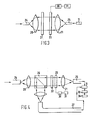
- a passive, self-contained transducer arrangement comprising a collimating lens pair 20, 21, a fixed polariser 22, and a rotatable polariser 23.
- the polariser 23 may be rotated by drive means 30 associated with a linearly movable device 31 requiring to have its linear position sensed or it can be rotated by drive means 30 associated with a rotatable device 31 requiring its angular position to be sensed.
- a rack and pinion drive can be used whilst in the second instance a gear drive, a pulley drive or toothed belt may be used, but any other suitable drive means may also be used.
- Light is introduced to the transducer arrangement from a remote source, e.g. that referenced 10 in Figure 1, via a light guide 24, e.g. a fibre-optic cable, and modulated light is returned from the arrangement via a light guide 25 to a remote detector, e.g. that referenced 11 in Figure 1.
- a remote source e.g. that referenced 10 in Figure 1
- a light guide 24 e.g. a fibre-optic cable
- modulated light is returned from the arrangement via a light guide 25 to a remote detector, e.g. that referenced 11 in Figure 1.
- the detector is fed a light signal which is an indication of the relative diaposition of the two polarisers 22, 23 and hence an indication of the position, either linear or angular, of the device the position or disposition of which is to be sensed.
- transducer arrangement including both a light source and detector could be made in an assembly approximately 1/4 inch (0.06 cm) in diameter and 1/2 inch (0.12 cm) in length. This naturally may be reduced if the source and detector are remotely positioned as in Figure 3.
- a laser light source that is to say a coherent beam
- a light guide of the type which maintains the polarisation relationship of the source the fixed polariser 22 can be dispensed with.
- an even pore compact transducer arrangement can be provided.
- FIG. 4 A very precise transducer arrangement having long term stability is illustrated in Figure 4. This uses a technique of differential-intensity referencing in which two fibre-optic output paths are provided, one for the polarisation modulated beam and one for a non-modulated reference beam.
- a beam splitter 26 is inserted into the optical path between the lens 20 and the fixed polariser 22.
- the beam splitter 26 diverts a non-modulated beam to an output light guide 27 via a lens similar to that referenced 21.
- the resulting twin beams, providing a reference signal and a modulated signal are coupled into a remote detector (e.g. reference 11 Figure 1) where any difference in intensity is measured. Any variation in source light intensity is removed when the two signals are subtracted, thus providing what is termed 'common mode rejection' in the electronics field.
- detector 11 there are many types of detector 11 existing which are suitable for use with this invention and the exact choice will be dependent upon the type of light source 10 used.
- the output from the detector 11 is an analogue signal representing the cosine of the angular position of the displaoeable polariser 23
- this signal is interfaced with a small analogue-to-digital (A/D) converter 32 to provide appropriate signals for a processing computer 34.
- A/D analogue-to-digital
- Resolution is dependent upon the AID converter and also to some extent upon the dynamic range of the detector 11.
- the transducer sensor arrangement is not the limiting element as far as resolution is concerned.
Landscapes
- Physics & Mathematics (AREA)
- General Physics & Mathematics (AREA)
- Length Measuring Devices By Optical Means (AREA)
- Optical Transform (AREA)
Applications Claiming Priority (2)
| Application Number | Priority Date | Filing Date | Title |
|---|---|---|---|
| GB868612404A GB8612404D0 (en) | 1986-05-21 | 1986-05-21 | Fibre optic position transducer |
| GB8612404 | 1986-05-21 |
Publications (2)
| Publication Number | Publication Date |
|---|---|
| EP0246892A2 true EP0246892A2 (de) | 1987-11-25 |
| EP0246892A3 EP0246892A3 (de) | 1988-03-23 |
Family
ID=10598235
Family Applications (1)
| Application Number | Title | Priority Date | Filing Date |
|---|---|---|---|
| EP87304518A Withdrawn EP0246892A3 (de) | 1986-05-21 | 1987-05-21 | Optischer Positionsumsetzer |
Country Status (3)
| Country | Link |
|---|---|
| EP (1) | EP0246892A3 (de) |
| DE (1) | DE246892T1 (de) |
| GB (1) | GB8612404D0 (de) |
Family Cites Families (5)
| Publication number | Priority date | Publication date | Assignee | Title |
|---|---|---|---|---|
| FR2326128A7 (fr) * | 1974-01-14 | 1977-04-22 | Fisson Jaubert Aubry Puymorin | Procede pour la production d'un courant electrique dont l'une au moins des caracteristiques est fonction du deplacement d'un mobile |
| FR2547049B1 (fr) * | 1983-06-03 | 1985-08-30 | Sereg Soc | Dispositif de telemesure par polarimetrie |
| JPS6082808A (ja) * | 1983-10-13 | 1985-05-11 | Yamatake Honeywell Co Ltd | 角度検出装置 |
| DE3428790A1 (de) * | 1983-12-01 | 1985-06-13 | Veb Kombinat Textima, Ddr 9010 Karl-Marx-Stadt | Fotoelektrischer beruehrungsloser lagegeber |
| JPS60263813A (ja) * | 1984-06-11 | 1985-12-27 | Brother Ind Ltd | 回転角検出装置 |
-
1986
- 1986-05-21 GB GB868612404A patent/GB8612404D0/en active Pending
-
1987
- 1987-05-21 EP EP87304518A patent/EP0246892A3/de not_active Withdrawn
- 1987-05-21 DE DE1987304518 patent/DE246892T1/de active Pending
Also Published As
| Publication number | Publication date |
|---|---|
| DE246892T1 (de) | 1988-09-22 |
| GB8612404D0 (en) | 1986-06-25 |
| EP0246892A3 (de) | 1988-03-23 |
Similar Documents
| Publication | Publication Date | Title |
|---|---|---|
| EP0577104B1 (de) | Optischer Stellungskodierer des Typs hybrid-digital-analog mit hoher Auflösung | |
| US4421980A (en) | Position encoder with closed-ring diode array | |
| US5442166A (en) | Linear absolute position sensor | |
| EP0169657B1 (de) | Kontaktloser Wellenwinkeldetektor | |
| US3983391A (en) | Optical encoder of the reflective type | |
| US5001937A (en) | Optically based torsion sensor | |
| CA2006107C (en) | Method and apparatus for determining the position of a mobile body | |
| US4606642A (en) | Measuring arrangement for the clear scanning of at least one reference mark allocated to a graduation | |
| KR20010074741A (ko) | 각 인코더 | |
| GB1426473A (en) | Digital length measuring means | |
| ATE128544T1 (de) | Positionskodierer für linear- oder winkelmessapparat. | |
| JPS60243514A (ja) | 光電的測定装置 | |
| JPS63168504A (ja) | 角度位置発信器 | |
| EP0509828B1 (de) | Optischer Enkoder mit verbessertem Index | |
| GB2084315A (en) | Interferometer | |
| US3244895A (en) | Shaft encoders | |
| EP0119488B1 (de) | Lageermittlungsgerät | |
| US4780600A (en) | Optical displacement transducer | |
| EP0638810A1 (de) | Kodierelement | |
| US5235177A (en) | Angular position sensor using a polarized disc with coded tracks | |
| US4733069A (en) | Position encoder using a laser scan beam | |
| EP0246892A2 (de) | Optischer Positionsumsetzer | |
| US5042157A (en) | Fiber optic angular orientation sensor digital serial encoding | |
| US4968145A (en) | Non-contacting revolving speed detecting apparatus | |
| JPH056845B2 (de) |
Legal Events
| Date | Code | Title | Description |
|---|---|---|---|
| PUAI | Public reference made under article 153(3) epc to a published international application that has entered the european phase |
Free format text: ORIGINAL CODE: 0009012 |
|
| AK | Designated contracting states |
Kind code of ref document: A2 Designated state(s): DE FR GB IT SE |
|
| PUAL | Search report despatched |
Free format text: ORIGINAL CODE: 0009013 |
|
| AK | Designated contracting states |
Kind code of ref document: A3 Designated state(s): DE FR GB IT SE |
|
| ITCL | It: translation for ep claims filed |
Representative=s name: SOCIETA' ITALIANA BREVETTI S.P.A. |
|
| EL | Fr: translation of claims filed | ||
| DET | De: translation of patent claims | ||
| STAA | Information on the status of an ep patent application or granted ep patent |
Free format text: STATUS: THE APPLICATION IS DEEMED TO BE WITHDRAWN |
|
| 18D | Application deemed to be withdrawn |
Effective date: 19880924 |
|
| RIN1 | Information on inventor provided before grant (corrected) |
Inventor name: KALAWSKY, ROY STEVEN |