EP0246830A2 - Optical information recording and reproducing apparatus - Google Patents
Optical information recording and reproducing apparatus Download PDFInfo
- Publication number
- EP0246830A2 EP0246830A2 EP87304349A EP87304349A EP0246830A2 EP 0246830 A2 EP0246830 A2 EP 0246830A2 EP 87304349 A EP87304349 A EP 87304349A EP 87304349 A EP87304349 A EP 87304349A EP 0246830 A2 EP0246830 A2 EP 0246830A2
- Authority
- EP
- European Patent Office
- Prior art keywords
- signal
- light beam
- change
- optical
- accordance
- Prior art date
- Legal status (The legal status is an assumption and is not a legal conclusion. Google has not performed a legal analysis and makes no representation as to the accuracy of the status listed.)
- Granted
Links
- 230000003287 optical effect Effects 0.000 title claims abstract description 51
- 230000001276 controlling effect Effects 0.000 claims 3
- 230000001105 regulatory effect Effects 0.000 claims 2
- 238000001514 detection method Methods 0.000 claims 1
- 230000015556 catabolic process Effects 0.000 description 7
- 230000007423 decrease Effects 0.000 description 7
- 238000006731 degradation reaction Methods 0.000 description 7
- 230000007547 defect Effects 0.000 description 5
- 239000000428 dust Substances 0.000 description 5
- 238000006243 chemical reaction Methods 0.000 description 4
- 230000001133 acceleration Effects 0.000 description 2
- 101000606504 Drosophila melanogaster Tyrosine-protein kinase-like otk Proteins 0.000 description 1
- 230000000694 effects Effects 0.000 description 1
- 238000000034 method Methods 0.000 description 1
- 239000004065 semiconductor Substances 0.000 description 1
- 230000035945 sensitivity Effects 0.000 description 1
Images


Classifications
-
- G—PHYSICS
- G11—INFORMATION STORAGE
- G11B—INFORMATION STORAGE BASED ON RELATIVE MOVEMENT BETWEEN RECORD CARRIER AND TRANSDUCER
- G11B19/00—Driving, starting, stopping record carriers not specifically of filamentary or web form, or of supports therefor; Control thereof; Control of operating function ; Driving both disc and head
- G11B19/20—Driving; Starting; Stopping; Control thereof
-
- G—PHYSICS
- G11—INFORMATION STORAGE
- G11B—INFORMATION STORAGE BASED ON RELATIVE MOVEMENT BETWEEN RECORD CARRIER AND TRANSDUCER
- G11B7/00—Recording or reproducing by optical means, e.g. recording using a thermal beam of optical radiation by modifying optical properties or the physical structure, reproducing using an optical beam at lower power by sensing optical properties; Record carriers therefor
- G11B7/002—Recording, reproducing or erasing systems characterised by the shape or form of the carrier
- G11B7/0033—Recording, reproducing or erasing systems characterised by the shape or form of the carrier with cards or other card-like flat carriers, e.g. flat sheets of optical film
-
- G—PHYSICS
- G11—INFORMATION STORAGE
- G11B—INFORMATION STORAGE BASED ON RELATIVE MOVEMENT BETWEEN RECORD CARRIER AND TRANSDUCER
- G11B7/00—Recording or reproducing by optical means, e.g. recording using a thermal beam of optical radiation by modifying optical properties or the physical structure, reproducing using an optical beam at lower power by sensing optical properties; Record carriers therefor
- G11B7/08—Disposition or mounting of heads or light sources relatively to record carriers
- G11B7/09—Disposition or mounting of heads or light sources relatively to record carriers with provision for moving the light beam or focus plane for the purpose of maintaining alignment of the light beam relative to the record carrier during transducing operation, e.g. to compensate for surface irregularities of the latter or for track following
- G11B7/0946—Disposition or mounting of heads or light sources relatively to record carriers with provision for moving the light beam or focus plane for the purpose of maintaining alignment of the light beam relative to the record carrier during transducing operation, e.g. to compensate for surface irregularities of the latter or for track following specially adapted for operation during external perturbations not related to the carrier or servo beam, e.g. vibration
Definitions
- the present invention relates to an optical information recording and reproducing apparatus for recording information on an optical information recording medium, reproducing the information recorded on the medium and/or erasing the information recorded on the medium.
- Such an information recording and reproducing apparatus is suitably used as an information recording and reproducing apparatus which uses a card-like information recording medium on which a plurality of linear information tracks are arranged in parallel.
- disk-shaped, card-shaped and tape-shaped media As a medium for recording information by using a light and reading the information thus recorded, disk-shaped, card-shaped and tape-shaped media have been known.
- the card-shaped optical information recording medium hereinafter referred to as an optical card
- the optical card is compact and light in weight, convenient to carry and has a large memory capacity. Accordingly, a big demand is expected.
- Fig. l shows a plan view of such an optical card l0l.
- Numeral l02 denotes an information record area
- numeral l03 denotes an information track
- numerals l04 and l04 ⁇ denote track select area
- numeral l05 denote a home position of a light beam spot.
- information is recorded as a line of optically detectable record bits (information track) by seanning the card by a light beam which is modulated by recording information and focused into a small spot.
- it is necessary to control (auto-tracking or AT) an irradiation position of the light beam spot on the optical card in a direction normal to a scan direction.
- it is necessary to control (auto-focusing or AF) the light beam spot in a direction normal to the optical card surface.
- the AT and AF are required in the reproduce mode.
- Fig. 2 shows a configuration of an apparatus for recording and reproducing information to and from the optical card.
- Numeral l06 denotes a motor for driving the optical card l0l in a direction of arrow
- numeral l07 denotes a light source such as a semiconductor laser
- numeral l08 denotes a collimeter lens
- numeral l09 denotes a beam splitter
- numeral ll0 denotes an objective lens
- numeral lll denotes a tracking coil
- numeral ll2 denotes a focusing coil
- numerals ll3 and ll4 denote condenser lenses
- numerals ll5 and ll6 denote photo-electric conversion elements
- numeral ll7 denotes a tracking control circuit
- numeral ll8 denotes a focusing control circuit.
- the light beam spot is initially at the home position l05.
- the light beam spot they moves on the track select area l04 in a direction u to find a record or reproduce track N, when the AT and AF are effected and the N is scanned in a direction r to record or reproduce information.
- a large current is momentarily supplied to the tracking coil lll (Fig. 2) so that the light beam spot is kicked to the track (N+l).
- the track (N+l) is scanned in the reverse direction l to record or reproduce information.
- the scan of the information track l03 by the light beam spot and the kick of the light beam spot in the track select areas l04 and l04 ⁇ are repeated several times.
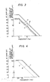
- Fig. 3 illustrates such frequency dependency. It shows the dependency in the AT direction. It is assumed that the skew is ⁇ l00 ⁇ m. Assuming that the vibration in the AT direction is generated merely by the skew, the frequency dependency of the amplitude of the vibration in the AT direction is represented by a , at a frequency up to a reciprocation frequency fs when the light beam spot scans, the amplitude is flat at l00 ⁇ m, and above the frequency fs, the amplitude decreases at a rate of -l2 dB/oct.
- the vibration in the AT direction is caused not only by the skew but also by the reversal of the reciprocal movement of the optical card.
- Such vibration occurs at a resonant frequency fp (fs ⁇ fp).
- fp fs ⁇ fp
- the vibration in the AT direction including the vibration at the reversal is represented by b in Fig. 3.
- the AT gain is raised as shown by ⁇ in Fig. 3.
- the AT is sufficiently attained at the reversal.
- the AT gain is higher than required, particularly in a high frequency band. Accordingly, the AT servo system is sensitive to a fine defect or dust on the surface of the optical card. This causes degradation of recorded or reproduced signal.
- the scan speed of the light beam spot in the ⁇ direction and l direction differs between the record mode and the reproduce mode.
- a relatively low scan speed is selected by the limitation such as record sensitivity of the record medium.
- the speed V W in the record mode is lower than a speed V R in the reproduce mode (V W ⁇ V R ). Since the scan distance in the record m is equal to the scan distance in the reproduce mode, a frequency f w of the reciprocation in the scan in the record mode is lower than a scan frequency f R in the reproduce mode (f W ⁇ f R ).
- the amplitude is flat at l00 ⁇ m at a frequency up to the recording scan frequency 0.5 Hz, and it decreases at a rate of -l2 dB/oct at a frequency above the scan frequency.
- the frequency dependency of the amplitude in the AT direction in the reproduce mode is represented by d .
- the amplitude is flat at l00 ⁇ m at a frequency up to the reproducing scan frequency 2.5 Hz, and it decreases at a rate of -l2 dB/oct at a frequency above the scan frequency.
- a light beam spot is reciprocally moved relative to an information track on the optical information recording medium while it is tracked and/or focused to record information on the recording medium, reproduce the information recorded on the recording medium and/or erase the information recorded on the recording medium.
- the direction and/or speed of the reciprocal movement are switched, and the tracking servo gain and/or focusing servo gain are switched by control means.
- Fig. 5 shows a configuration of an optical card recording and reproducing apparatus which is the optical information recording and reproducing apparatus of the present invention.
- the like elements to those shown in Fig. 2 are designated by the like numerals, and the explanation thereof is omitted.
- numerals l2l and l22 denote a tracking control circuit and a focusing control circuit, respectively.
- numeral l2l-l denotes an amplifier which amplifies an electrical tracking signal supplied from a photo-electric conversion element ll5 to an appropriate voltage.
- Numeral l2l-2 denotes an analog switch. Signal is supplied from the amplifier l2l-l through terminals C and D.
- Numeral l2l-3 denotes a driver which receives the signal from the analog switch l2l-2 to supply a drive signal current to a tracking coil lll.
- numeral l22-l denotes an amplifier which amplifies an electrical focusing signal supplied from a photo-electric conversion element ll6 to an appropriate voltage.
- Numeral l22-2 denotes an analog switch. The signal from the amplifier l22-l is supplied thereto through terminals A and B.
- Numeral l22-3 denotes a driver which receives the signal from the analog switch l22-2 to supply a drive signal current to the focusing coil ll2.
- numeral l23 denotes a system controller which controls the recording and reproducing apparatus
- numeral l24 denotes a signal produced by the controller to control the direction of movement of the optical card (i.e., the direction of rotation of a motor l06).
- the controller l23 also produces other signals than l24 although they are not shown.
- Numeral l25 denotes a motor driver which receives the signal l24 to control the direction of rotation of the motor l06.
- Numeral l26 denotes a one-shot multivibrator which receives the signal l24 to produce a signal l27 when the signal l24 transits.
- Fig. 6 shows a time chart showing a relation between the signals l24 and l27.
- pulse signals l27 having a width t are produced.
- l and ⁇ represent the directions of movement of the optical card l0l by the motor l06 in accordance with the signal l24.
- the reversal of the direction of movement of the optical card is effected within a time period of the pulse width t of the signal l27.
- the motor controller l25 starts the deceleration when the level of the signal l24 changes, stops the deceleration at the mid-point of the time period t, starts the acceleration in the opposite direction, and drives the motor at a steady speed at the mid-point of the time period t.
- the signal l27 is applied to the analog switches l2l-2 and l22-2, which control the status of the switches.
- the pulse signal l27 is present (reversal)
- the terminal C of the switch l2l-2 is closed and the terminal D is open.
- the terminal A is closed and the terminal B is open.
- the pulse signal l27 is not present (non-reversal)
- the terminal C of the switch l2l-2 is open and the terminal D is closed.
- the terminal A is open and the terminal B is closed.
- the outputs from the amplifiers l2l-l and l22-l are divided and they are supplied to the drivers l2l-3 and l22-3, respectively.
- the output voltages from the amplifiers l2l-l and l22-l are not divided and supplied to the drivers l2l-3 and l22-3, respectively.
- the AT gain and AF gain at the reversal time can be higher than those at the non-reversal time.
- e shows the vibration in the AT direction only at the non-reversal time
- f shows the vibration in the AT direction including the reversal time.
- the AT gain is set to assume ⁇ shown in Fig. 7 at the reversal time (that is, when the output from the amplifier l2l-l is applied to the driver l2l-3 through the terminal C).
- the output from the amplifier l2l-l is supplied to the driver l2l-3 through the terminal D and the AT gain assumes ⁇ shown in Fig. 7 which is a shift-down version of ⁇ .
- the ⁇ may be set to be equal to ⁇ shown in Fig. 3 by appropriately selecting a resistance between the terminals C and D and other constants.
- the AT gain ⁇ at the reversal time is raised relative to the AT gain ⁇ at the non-reversal time. This is not absolutely necessary but it is sufficient to cover the vibration around the resonance frequency fp.
- the direction of relative reciprocal movement between the light beam spot and the information track of the optical information recording medium is switched and the tracking servo gain and/or focusing servo gain are also switched so that a minimum required gain is set for each circumstance.
- the degradation of the recorded and reproduced signals by the affect of defect or dust on the surface of the recording medium is prevented, and at the reversal time, the off-AT and off-AF are prevented. Accordingly, the reliability and error rate are improved.
- Fig. 8 shows a configuration of another embodiment of the optical card recording and reproducing apparatus which is the optical information recording and reproducing apparatus of the present invention.
- the like elements to those shown in Fig. 5 are designated by the like numerals and the explanation thereof is omitted.
- numeral l23 denotes a system controller which controls the recording and reproducing apparatus
- numeral l34 denotes a record mode/reproduce mode select control signal produced by the controller.
- the controller l23 also produces signals other than l34 although they are not shown.
- Numeral l35 denotes a motor driver which receives the signal l34 to set the rotation speed of the motor l06 to the recording or reproducing speed.
- the signal l34 is applied to the analog switches l2l-l and l22-2 to control the status of the switches.
- the reproduce mode signal l34 When the reproduce mode signal l34 is applied, the terminal C of the switch l2l-2 is closed and the terminal D is open. In the switch l22-2, the terminal A is closed and the terminal B is open.
- the record mode signal l34 when the record mode signal l34 is applied, the terminal C of the switch l2l-2 is open and the terminal D is closed. In the switch l22-2, the terminal A is open and the terminal B is closed. Accordingly, in the record mode, the output voltages from the amplifiers l2l-l and l22-l are divided and they are supplied to the drivers l2l-3 and l22-3.
- the output voltages from the amplifiers l2l-l and l22-l are not divided and supplied to the drivers l2l-3 and l22-3, respectively.
- the AT gain and AF gain in the record mode may be set lower than those in the reproduce mode.
- Fig. 9 shows a graph of frequency characteristics of the amplitude of vibration in the AT direction and the AT gain.
- g represents a vibration in the AT direction in the record mode
- h represents a vibration in the AT direction in the reproduce mode. They are similar to c and d shown in Fig. 4.
- the AT gain in the record mode (that is, when the output of the amplifier l2l-l is applied to the driver l2l-3 through the terminal D) is set to assume ⁇ of Fig. 9.
- the ⁇ is 60 dB at a frequency below the recording scan frequency 0.5 Hz and decreases at a rate of -l2 dB/oct at a frequency above the scan frequency.
- the output of the amplifier l2l-l is applied to the driver l2l-3 through the terminal C.
- the AT gain assumes ⁇ of Fig. 9 which is a shift-up version of ⁇ .
- the ⁇ is 60 dB at the reproducing scan frequency 2.5 Hz and decreases at a rate of -l2 dB/oct at a frequency above the scan frequency.
- the AT gain ⁇ in the record mode is lower than the AT gain ⁇ in the reproduce mode.
- the AT gain in the record mode may be ⁇ which is lower than the AT gain in the reproduce mode only in the high frequency band.
- the speed of the relative reciprocal movement between the light beam spot and the information track of the optical information recording medium is switched, and the tracking servo gain and/or focusing servo gain are switched so that a minimum required gain is set for each circumstance. Accordingly, at the low speed, the degradation of signal by the affect of defect and dust on the surface of the recording medium due to overgain is prevented, and at the high speed, the off-AT and off-AF are prevented. Thus, the reliability and error rate are improved.
- the gain is electrically changed.
- the gain may be changed optically, mechanically or electrically, or by combination thereof, because the AT gain and AF gain are determined by the products of the electrical gain, optical gain and mechanical gain.
- the intensity of the light source l07 may be changed, an ND filter may be inserted into a light path, or a variable transmissibility ND filter may be used to change the transmissibility of the filter.
- the mechanical gain the number of turns of the tracking coil lll may be changed or a distance between the tracking coil lll and a magnet which is integral with the objective lens ll0 may be changed.
Landscapes
- Optical Recording Or Reproduction (AREA)
Abstract
Description
- The present invention relates to an optical information recording and reproducing apparatus for recording information on an optical information recording medium, reproducing the information recorded on the medium and/or erasing the information recorded on the medium. Such an information recording and reproducing apparatus is suitably used as an information recording and reproducing apparatus which uses a card-like information recording medium on which a plurality of linear information tracks are arranged in parallel.
- As a medium for recording information by using a light and reading the information thus recorded, disk-shaped, card-shaped and tape-shaped media have been known. Of those, the card-shaped optical information recording medium (hereinafter referred to as an optical card) is compact and light in weight, convenient to carry and has a large memory capacity. Accordingly, a big demand is expected.
- Fig. l shows a plan view of such an optical card l0l. Numeral l02 denotes an information record area, numeral l03 denotes an information track, numerals l04 and l04ʹ denote track select area, and numeral l05 denote a home position of a light beam spot.
- On the optical card, information is recorded as a line of optically detectable record bits (information track) by seanning the card by a light beam which is modulated by recording information and focused into a small spot. In order to exactly record information without trouble such as crossing of information tracks, it is necessary to control (auto-tracking or AT) an irradiation position of the light beam spot on the optical card in a direction normal to a scan direction. In order to irradiate the light beam as a stable small spot irrespective of curvature of the optical card or mechanical tolerance, it is necessary to control (auto-focusing or AF) the light beam spot in a direction normal to the optical card surface. Further, the AT and AF are required in the reproduce mode.
- Fig. 2 shows a configuration of an apparatus for recording and reproducing information to and from the optical card. Numeral l06 denotes a motor for driving the optical card l0l in a direction of arrow, numeral l07 denotes a light source such as a semiconductor laser, numeral l08 denotes a collimeter lens, numeral l09 denotes a beam splitter, numeral ll0 denotes an objective lens, numeral lll denotes a tracking coil, numeral ll2 denotes a focusing coil, numerals ll3 and ll4 denote condenser lenses, numerals ll5 and ll6 denote photo-electric conversion elements, numeral ll7 denotes a tracking control circuit and numeral ll8 denotes a focusing control circuit. Currents are supplied to the tracking coil lll and focusing coil ll2 by commands from the control circuits ll7 and ll8 in accordance with tracking signal and focusing signal detected by the photo-electric conversion elements ll5 and ll6 so that the objective lens ll0 is driven to effect the AT and AF.
- A method for recording and reproducing information is explained with reference to Figs. l and 2. The light beam spot is initially at the home position l05. The light beam spot them moves on the track select area l04 in a direction u to find a record or reproduce track N, when the AT and AF are effected and the N is scanned in a direction r to record or reproduce information. When the light beam spot comes into the track select area l04ʹ, a large current is momentarily supplied to the tracking coil lll (Fig. 2) so that the light beam spot is kicked to the track (N+l). Then, the track (N+l) is scanned in the reverse direction ℓ to record or reproduce information. Depending on amount of information, the scan of the information track l03 by the light beam spot and the kick of the light beam spot in the track select areas l04 and l04ʹ are repeated several times.
- In such an information recording and reproducing apparatus, when the optical card l0l is reciprocally driven by the motor l06, vibration is generated in the directions of AT and AF, because the light beam spot may be off-tracked in the direction of AT from the information track due to skew of the information track relative to the contour of the optical card and a backlash of the optical card drive mechanism and the AT control attempts to compensate for such off-track. On the other hand, in the direction of AF, the light beam spot may be defocused from the record plane of the optical card due to curvature of the optical card and the backlash of the optical card drive mechanism, and the AF control attempts to compensate it.
- It has been known that the amplitude of such vibration depends on a frequency. Fig. 3 illustrates such frequency dependency. It shows the dependency in the AT direction. It is assumed that the skew is ±l00 µm. Assuming that the vibration in the AT direction is generated merely by the skew, the frequency dependency of the amplitude of the vibration in the AT direction is represented by a, at a frequency up to a reciprocation frequency fs when the light beam spot scans, the amplitude is flat at l00 µm, and above the frequency fs, the amplitude decreases at a rate of -l2 dB/oct. In order to keep the deviation in the AT within ±0.l µm, an open loop gain GT of the AT servo at the frequency below the scan frequency ts is
GT = 20 log (l00/0.l) = 60 dB
as shown by α in Fig. 3, and it decreases at the rate of -l2 dB/oct at the frequency above the scan frequency. - However, the vibration in the AT direction is caused not only by the skew but also by the reversal of the reciprocal movement of the optical card. Such vibration occurs at a resonant frequency fp (fs < fp). This is due to mechanical vibration of the drive mechanism by abrupt deceleration and obrupt opposite acceleration upon the reversal of the reciprocal movement of the optical card. The vibration in the AT direction including the vibration at the reversal is represented by b in Fig. 3. In order to keep the deviation of AT within ±0.l µm under the vibration at the reversal, the AT gain is raised as shown by β in Fig. 3.
- As a result, the AT is sufficiently attained at the reversal. However, at a time other than the reversal, the AT gain is higher than required, particularly in a high frequency band. Accordingly, the AT servo system is sensitive to a fine defect or dust on the surface of the optical card. This causes degradation of recorded or reproduced signal.
- The same is true for the AF direction.
- In the information recording and reproducing apparatus described above, the scan speed of the light beam spot in the γ direction and ℓ direction differs between the record mode and the reproduce mode. In the record mode, a relatively low scan speed is selected by the limitation such as record sensitivity of the record medium. Thus, the speed VW in the record mode is lower than a speed VR in the reproduce mode (VW < VR). Since the scan distance in the record m is equal to the scan distance in the reproduce mode, a frequency fw of the reciprocation in the scan in the record mode is lower than a scan frequency fR in the reproduce mode (fW < fR).
- On the other hand, in the information recording and reproducing apparatus described above, when the optical card l0l is reciprocally driven by the motor l06, vibrations are generated in the AT and AF directions. It has been known that the amplitude of the vibration depends on the frequency of the vibration. Fig. 4 illustrates such frequency dependency. It shows the dependency in the AT direction. It is assumed that a recording scan frequency fW is 0.5 Hz, a reproducing scan frequency fR is 2.5 Hz and a skew is ±l00 µm. Assuming that the vibration in the AT direction is generated merely by the skew, the frequency dependency of the amplitude of the vibration in the AT direction in the record mode is represented by c. The amplitude is flat at l00 µm at a frequency up to the recording scan frequency 0.5 Hz, and it decreases at a rate of -l2 dB/oct at a frequency above the scan frequency. On the other hand, the frequency dependency of the amplitude in the AT direction in the reproduce mode is represented by d. The amplitude is flat at l00 µm at a frequency up to the reproducing scan frequency 2.5 Hz, and it decreases at a rate of -l2 dB/oct at a frequency above the scan frequency.
- In order to keep the deviation of AT within ±0.l µm in both the record mode and the reproduce mode, the open loop gain GT of the AT servo is set as shown by α in Fig. 4. Namely, at a frequency below the reproducing scan frequency 2.5 Hz,
GT = 20 log (l00/0.l) = 60 dB
and it decreases at a rate of -l2 dB/oct at a frequency above the scan frequency. - As a result, sufficient AT control is effected in both the record mode and the reproduce mode. However, in the record mode, since the AT gain in a high frequency band is higher than required, the AT servo system is sensitive to a fine defect or dust on the surface of the optical card. This causes degradation of a recorded signal.
- The same applies to the AF direction.
- It is an object of the present invention to provide an optical information recording and reproducing apparatus which resolves the problems encountered in the prior art apparatus, does not cause degradation of recorded and reproduced signals by the affect of defect or dust on the surface of the recording medium, does not cause off-AT or off-AF, and improves reliability and an error rate.
- In order to achieve the above object, in accordance with the present invention, a light beam spot is reciprocally moved relative to an information track on the optical information recording medium while it is tracked and/or focused to record information on the recording medium, reproduce the information recorded on the recording medium and/or erase the information recorded on the recording medium. The direction and/or speed of the reciprocal movement are switched, and the tracking servo gain and/or focusing servo gain are switched by control means.
-
- Fig. l shows a plan view of an optical card,
- Fig. 2 shows a configuration of a prior art optical card recording and reproducing apparatus,
- Figs. 3, 4, 7, 9, and l0 show graphs of amplitudes of vibration in AT direction and AT servo gains,
- Fig. 5 shows a configuration of an optical card recording and reproducing apparatus of the present invention,
- Fig. 6 shows a signal time chart, and
- Fig. 8 shows another embodiment of the optical card recording and reproducing apparatus of the present invention.
- Fig. 5 shows a configuration of an optical card recording and reproducing apparatus which is the optical information recording and reproducing apparatus of the present invention. The like elements to those shown in Fig. 2 are designated by the like numerals, and the explanation thereof is omitted.
- In Fig. 5, numerals l2l and l22 denote a tracking control circuit and a focusing control circuit, respectively. In the tracking control circuit l2l, numeral l2l-l denotes an amplifier which amplifies an electrical tracking signal supplied from a photo-electric conversion element ll5 to an appropriate voltage. Numeral l2l-2 denotes an analog switch. Signal is supplied from the amplifier l2l-l through terminals C and D. Numeral l2l-3 denotes a driver which receives the signal from the analog switch l2l-2 to supply a drive signal current to a tracking coil lll. In the focusing control circuit l22, numeral l22-l denotes an amplifier which amplifies an electrical focusing signal supplied from a photo-electric conversion element ll6 to an appropriate voltage. Numeral l22-2 denotes an analog switch. The signal from the amplifier l22-l is supplied thereto through terminals A and B. Numeral l22-3 denotes a driver which receives the signal from the analog switch l22-2 to supply a drive signal current to the focusing coil ll2.
- In Fig. 5, numeral l23 denotes a system controller which controls the recording and reproducing apparatus, and numeral l24 denotes a signal produced by the controller to control the direction of movement of the optical card (i.e., the direction of rotation of a motor l06). The controller l23 also produces other signals than l24 although they are not shown. Numeral l25 denotes a motor driver which receives the signal l24 to control the direction of rotation of the motor l06. Numeral l26 denotes a one-shot multivibrator which receives the signal l24 to produce a signal l27 when the signal l24 transits. Fig. 6 shows a time chart showing a relation between the signals l24 and l27. When the signal l24 changes from an L level to an H level and from the H level to the L level, pulse signals l27 having a width t are produced. In Figs. 5 and 6, ℓ and γ represent the directions of movement of the optical card l0l by the motor l06 in accordance with the signal l24. As shown, the reversal of the direction of movement of the optical card is effected within a time period of the pulse width t of the signal l27. The motor controller l25 starts the deceleration when the level of the signal l24 changes, stops the deceleration at the mid-point of the time period t, starts the acceleration in the opposite direction, and drives the motor at a steady speed at the mid-point of the time period t.
- The signal l27 is applied to the analog switches l2l-2 and l22-2, which control the status of the switches. When the pulse signal l27 is present (reversal), the terminal C of the switch l2l-2 is closed and the terminal D is open. In the switch l22-2, the terminal A is closed and the terminal B is open. On the other hand, when the pulse signal l27 is not present (non-reversal), the terminal C of the switch l2l-2 is open and the terminal D is closed. In the switch l22-2, the terminal A is open and the terminal B is closed. Accordingly, at the non-reversal time, the outputs from the amplifiers l2l-l and l22-l are divided and they are supplied to the drivers l2l-3 and l22-3, respectively. On the other hand, at the reversal time, the output voltages from the amplifiers l2l-l and l22-l are not divided and supplied to the drivers l2l-3 and l22-3, respectively. Thus, the AT gain and AF gain at the reversal time can be higher than those at the non-reversal time.
- In Fig. 7, e shows the vibration in the AT direction only at the non-reversal time, and f shows the vibration in the AT direction including the reversal time. They are similar to a and b shown in Fig. 3, respectively. In the present embodiment, the AT gain is set to assume ε shown in Fig. 7 at the reversal time (that is, when the output from the amplifier l2l-l is applied to the driver l2l-3 through the terminal C). At the non-reversal time, the output from the amplifier l2l-l is supplied to the driver l2l-3 through the terminal D and the AT gain assumes δ shown in Fig. 7 which is a shift-down version of ε. The δ may be set to be equal to α shown in Fig. 3 by appropriately selecting a resistance between the terminals C and D and other constants.
- Thus, at the non-reversal time, the degradation of the recorded and reproduced signals due to over-sensitivity by the overgain is prevented. At the reversal time, sufficient AT and AF are attained even under a large high frequency vibration. At the reversal time, information is not recorded or reproduced and hence the signal is not degradated.
- Similar gain setting may be done for the AF direction.
- In the above embodiment, as shown in Fig. 7, the AT gain ε at the reversal time is raised relative to the AT gain δ at the non-reversal time. This is not absolutely necessary but it is sufficient to cover the vibration around the resonance frequency fp.
- In accordance with the present invention, the direction of relative reciprocal movement between the light beam spot and the information track of the optical information recording medium is switched and the tracking servo gain and/or focusing servo gain are also switched so that a minimum required gain is set for each circumstance. Thus, at the non-reversal time, the degradation of the recorded and reproduced signals by the affect of defect or dust on the surface of the recording medium is prevented, and at the reversal time, the off-AT and off-AF are prevented. Accordingly, the reliability and error rate are improved.
- Fig. 8 shows a configuration of another embodiment of the optical card recording and reproducing apparatus which is the optical information recording and reproducing apparatus of the present invention. The like elements to those shown in Fig. 5 are designated by the like numerals and the explanation thereof is omitted.
- In Fig. 8, numeral l23 denotes a system controller which controls the recording and reproducing apparatus, and numeral l34 denotes a record mode/reproduce mode select control signal produced by the controller. The controller l23 also produces signals other than l34 although they are not shown. Numeral l35 denotes a motor driver which receives the signal l34 to set the rotation speed of the motor l06 to the recording or reproducing speed.
- The signal l34 is applied to the analog switches l2l-l and l22-2 to control the status of the switches. When the reproduce mode signal l34 is applied, the terminal C of the switch l2l-2 is closed and the terminal D is open. In the switch l22-2, the terminal A is closed and the terminal B is open. On the other hand, when the record mode signal l34 is applied, the terminal C of the switch l2l-2 is open and the terminal D is closed. In the switch l22-2, the terminal A is open and the terminal B is closed. Accordingly, in the record mode, the output voltages from the amplifiers l2l-l and l22-l are divided and they are supplied to the drivers l2l-3 and l22-3. On the other hand, in the reproduce mode, the output voltages from the amplifiers l2l-l and l22-l are not divided and supplied to the drivers l2l-3 and l22-3, respectively. Thus, the AT gain and AF gain in the record mode may be set lower than those in the reproduce mode.
- Fig. 9 shows a graph of frequency characteristics of the amplitude of vibration in the AT direction and the AT gain.
- In Fig. 9, g represents a vibration in the AT direction in the record mode, and h represents a vibration in the AT direction in the reproduce mode. They are similar to c and d shown in Fig. 4. In the present embodiment, the AT gain in the record mode (that is, when the output of the amplifier l2l-l is applied to the driver l2l-3 through the terminal D) is set to assume ζ of Fig. 9. The ζ is 60 dB at a frequency below the recording scan frequency 0.5 Hz and decreases at a rate of -l2 dB/oct at a frequency above the scan frequency. In the reproduce mode, the output of the amplifier l2l-l is applied to the driver l2l-3 through the terminal C. Thus, the AT gain assumes η of Fig. 9 which is a shift-up version of ζ. By appropriately selecting the resistance between the terminals C and D of Fig. 8 and other constants, the η is 60 dB at the reproducing scan frequency 2.5 Hz and decreases at a rate of -l2 dB/oct at a frequency above the scan frequency.
- Thus, in the record mode, the degradation of the recorded signal due to the oversensitivity by the overgain is prevented, and in the reproduce mode, sufficient AT and AF are attained.
- Similar gain setting may be done for the AF direction.
- In the above embodiment, as shown in Fig. 9, the AT gain ζ in the record mode is lower than the AT gain η in the reproduce mode. However, this is not absolutely necessary. For example, as shown in Fig. l0, the AT gain in the record mode may be ζʹ which is lower than the AT gain in the reproduce mode only in the high frequency band.
- In accordance with the present invention, the speed of the relative reciprocal movement between the light beam spot and the information track of the optical information recording medium is switched, and the tracking servo gain and/or focusing servo gain are switched so that a minimum required gain is set for each circumstance. Accordingly, at the low speed, the degradation of signal by the affect of defect and dust on the surface of the recording medium due to overgain is prevented, and at the high speed, the off-AT and off-AF are prevented. Thus, the reliability and error rate are improved.
- In the above two embodiments, the gain is electrically changed. Alternatively, the gain may be changed optically, mechanically or electrically, or by combination thereof, because the AT gain and AF gain are determined by the products of the electrical gain, optical gain and mechanical gain. In order to change the optical gain, the intensity of the light source l07 may be changed, an ND filter may be inserted into a light path, or a variable transmissibility ND filter may be used to change the transmissibility of the filter. In order to change the mechanical gain, the number of turns of the tracking coil lll may be changed or a distance between the tracking coil lll and a magnet which is integral with the objective lens ll0 may be changed.
Claims (6)
a light source;
first optical means for guiding a light beam from said light source, onto the record medium;
second optical means for obtaining the light beam from the record medium;
detecting means for receiving the light beam obtained by said second optical means to output at least one of a focusing signal and a tracking signal;
adjusting means for adjusting at least one of focusing and tracking operations in accordance with at least one of the focusing and tracking signals;
reciprocating means for causing the record medium to reciprocate;
control means for controlling the reciprocating means; and
change means for changing at least a servo gain of said adjusting means in accordance with at least a signal from said control means.
means for moving a light beam and optical record medium relative to each other in at least two different modes;
means for regulating the relative movement of the light beam and the medium;
means for detecting the propriety with which the light beam impinges on the medium; and
means for controlling the regulating means in dependence upon the detection by the detecting means;
characterised by:
means to change the degree of control by the controlling means in dependence upon the mode of movement of the moving means.
Applications Claiming Priority (4)
| Application Number | Priority Date | Filing Date | Title |
|---|---|---|---|
| JP113512/86 | 1986-05-20 | ||
| JP61113512A JPH079706B2 (en) | 1986-05-20 | 1986-05-20 | Optical information recording / reproducing device |
| JP113511/86 | 1986-05-20 | ||
| JP11351186A JPS62271230A (en) | 1986-05-20 | 1986-05-20 | Optical information recording and reproducing device |
Publications (3)
| Publication Number | Publication Date |
|---|---|
| EP0246830A2 true EP0246830A2 (en) | 1987-11-25 |
| EP0246830A3 EP0246830A3 (en) | 1989-03-15 |
| EP0246830B1 EP0246830B1 (en) | 1992-08-05 |
Family
ID=26452465
Family Applications (1)
| Application Number | Title | Priority Date | Filing Date |
|---|---|---|---|
| EP87304349A Expired EP0246830B1 (en) | 1986-05-20 | 1987-05-15 | Optical information recording and reproducing apparatus |
Country Status (4)
| Country | Link |
|---|---|
| US (1) | US4888756A (en) |
| EP (1) | EP0246830B1 (en) |
| CA (1) | CA1301324C (en) |
| DE (1) | DE3780866T2 (en) |
Cited By (6)
| Publication number | Priority date | Publication date | Assignee | Title |
|---|---|---|---|---|
| EP0325488A1 (en) * | 1988-01-22 | 1989-07-26 | Sharp Kabushiki Kaisha | Analog signal switching device for use in an optical memory device |
| EP0383562A1 (en) * | 1989-02-15 | 1990-08-22 | Canon Kabushiki Kaisha | Optical information recording and/or reproducing apparatus with device for prohibiting movement of optical head |
| EP0388519A3 (en) * | 1989-03-20 | 1990-11-22 | Pioneer Electronic Corporation | Method for setting the loop gain of servo loops in a disc player |
| FR2652435A1 (en) * | 1989-09-14 | 1991-03-29 | Mitsubishi Electric Corp | OPTICAL READ / WRITE APPARATUS HAVING VERY GOOD TRACK TRACKING PERFORMANCE. |
| EP0536558A1 (en) * | 1991-10-09 | 1993-04-14 | Nippon Conlux Co., Ltd. | Apparatus for optically recording and reproducing information |
| EP0547630A3 (en) * | 1991-12-18 | 1994-09-07 | Hewlett Packard Co | Adaptive control system for a disk drive actuator |
Families Citing this family (9)
| Publication number | Priority date | Publication date | Assignee | Title |
|---|---|---|---|---|
| US5029151A (en) * | 1988-02-17 | 1991-07-02 | Canon Kabushiki Kaisha | Optical information processing apparatus including a limiter for limiting error of focusing and/or tracking actuators and a circuit for adjusting the limit range thereof |
| US5341355A (en) * | 1988-05-20 | 1994-08-23 | Ricoh Company, Ltd. | Multibeam optical pickup and servo method thereof |
| JP2904434B2 (en) * | 1988-08-12 | 1999-06-14 | パイオニア株式会社 | Optical information recording medium and reproducing apparatus therefor |
| JP2723646B2 (en) * | 1990-03-27 | 1998-03-09 | キヤノン株式会社 | Optical information processing device |
| JP2531847B2 (en) * | 1990-09-27 | 1996-09-04 | インターナシヨナル・ビジネス・マシーンズ・コーポレーシヨン | Optical disk drive |
| GB2248989B (en) * | 1990-10-15 | 1995-05-24 | Applied Magnetics Corp | Focus sensing apparatus and method |
| US6371370B2 (en) * | 1999-05-24 | 2002-04-16 | Agilent Technologies, Inc. | Apparatus and method for scanning a surface |
| JP3824135B2 (en) * | 2001-01-10 | 2006-09-20 | 横河電機株式会社 | Biochip reader |
| CN105637527B (en) * | 2013-10-29 | 2017-12-05 | 美国索尼公司 | The array reader and array of optical medium are read |
Family Cites Families (13)
| Publication number | Priority date | Publication date | Assignee | Title |
|---|---|---|---|---|
| US3474418A (en) * | 1967-06-19 | 1969-10-21 | Ibm | Data tracking system |
| JPS626580Y2 (en) * | 1979-11-17 | 1987-02-16 | ||
| JPS58166567A (en) * | 1982-03-26 | 1983-10-01 | Matsushita Electric Ind Co Ltd | Retrieving device of information track |
| JPS59116939A (en) * | 1982-12-23 | 1984-07-06 | Olympus Optical Co Ltd | Optical recording and reproducing device |
| NL8300844A (en) * | 1983-03-09 | 1984-10-01 | Philips Nv | DEVICE FOR READING AN OPTICALLY CODED DISC REGISTRATION CARRIER. |
| JPS59198537A (en) * | 1983-04-22 | 1984-11-10 | Matsushita Electric Ind Co Ltd | Optical recording and reproducing device |
| NL8303029A (en) * | 1983-08-31 | 1985-03-18 | Philips Nv | DEVICE FOR READING A DISC-SHAPED OPTICAL RECORD CARRIER. |
| JP2719549B2 (en) * | 1983-10-12 | 1998-02-25 | ドレクスラ−・テクノロジ−・コ−ポレ−ション | 4x density optical data system |
| US4634850A (en) * | 1983-10-12 | 1987-01-06 | Drexler Technology Corporation | Quad density optical data system |
| US4734565A (en) * | 1983-10-12 | 1988-03-29 | Drexler Technology Corporation | Read-only optical card and system |
| US4598393A (en) * | 1984-04-06 | 1986-07-01 | Drexler Technology Corporation | Three-beam optical servo tracking system with two-track parallel readout |
| FR2575578B1 (en) * | 1984-12-31 | 1995-03-03 | Canon Kk | APPARATUS FOR OPTICAL INFORMATION RECORDING AND REPRODUCTION |
| JPH0664632B2 (en) * | 1985-09-06 | 1994-08-22 | キヤノン株式会社 | Information recording / reproducing device |
-
1987
- 1987-05-15 CA CA000537266A patent/CA1301324C/en not_active Expired - Lifetime
- 1987-05-15 EP EP87304349A patent/EP0246830B1/en not_active Expired
- 1987-05-15 DE DE8787304349T patent/DE3780866T2/en not_active Expired - Fee Related
-
1988
- 1988-12-30 US US07/291,368 patent/US4888756A/en not_active Expired - Lifetime
Cited By (7)
| Publication number | Priority date | Publication date | Assignee | Title |
|---|---|---|---|---|
| EP0325488A1 (en) * | 1988-01-22 | 1989-07-26 | Sharp Kabushiki Kaisha | Analog signal switching device for use in an optical memory device |
| US4906874A (en) * | 1988-01-22 | 1990-03-06 | Sharp Kabushiki Kaisha | Analog signal switching device for use in an optical memory |
| EP0383562A1 (en) * | 1989-02-15 | 1990-08-22 | Canon Kabushiki Kaisha | Optical information recording and/or reproducing apparatus with device for prohibiting movement of optical head |
| EP0388519A3 (en) * | 1989-03-20 | 1990-11-22 | Pioneer Electronic Corporation | Method for setting the loop gain of servo loops in a disc player |
| FR2652435A1 (en) * | 1989-09-14 | 1991-03-29 | Mitsubishi Electric Corp | OPTICAL READ / WRITE APPARATUS HAVING VERY GOOD TRACK TRACKING PERFORMANCE. |
| EP0536558A1 (en) * | 1991-10-09 | 1993-04-14 | Nippon Conlux Co., Ltd. | Apparatus for optically recording and reproducing information |
| EP0547630A3 (en) * | 1991-12-18 | 1994-09-07 | Hewlett Packard Co | Adaptive control system for a disk drive actuator |
Also Published As
| Publication number | Publication date |
|---|---|
| EP0246830B1 (en) | 1992-08-05 |
| DE3780866T2 (en) | 1993-03-18 |
| US4888756A (en) | 1989-12-19 |
| DE3780866D1 (en) | 1992-09-10 |
| CA1301324C (en) | 1992-05-19 |
| EP0246830A3 (en) | 1989-03-15 |
Similar Documents
| Publication | Publication Date | Title |
|---|---|---|
| EP0246830A2 (en) | Optical information recording and reproducing apparatus | |
| EP0256827B1 (en) | Apparatus for recording and reproducing data into/from an optical disc | |
| US5146442A (en) | Method and apparatus for effecting at least one of tracking and servo control when an error signal passes a zero-cross point and reaches a predetermined non-zero value | |
| US5163034A (en) | Tracking device to effect tracking pull-in in an optical recording and reproducing apparatus by vibrating a light spot | |
| US5099468A (en) | Optical information processing apparatus having offset adjusting circuit which can be exchanged together with optical head | |
| JPH01223640A (en) | Optical recording and reproducing device | |
| US5138596A (en) | Optical information recording apparatus including means for delaying servo gain by a predetermined time | |
| US5475660A (en) | Optical information recording-reproducing method and apparatus including focusing and/or tracking control depending on a determined state of an optical spot | |
| US5029151A (en) | Optical information processing apparatus including a limiter for limiting error of focusing and/or tracking actuators and a circuit for adjusting the limit range thereof | |
| US5124964A (en) | Focus servo gain setting circuit for optical record disc reproducing apparatus | |
| US5200937A (en) | Apparatus for and method of recording and/or reproducing information by means of two actuators | |
| JPH05182224A (en) | Optical disk device | |
| EP0315470A2 (en) | Focus search drive apparatus for an optical disc player | |
| US4785440A (en) | Method and apparatus for driving an optical pickup of an optical information recording and reproducing apparatus | |
| JPH02282973A (en) | Optical information recording and reproducing device | |
| KR100628184B1 (en) | Actuator control device of optical recorder | |
| JPH079706B2 (en) | Optical information recording / reproducing device | |
| JP2664739B2 (en) | Information recording / reproducing device | |
| JPH0682468B2 (en) | Optical information recording / reproducing device | |
| JP2702177B2 (en) | Information recording / reproducing device | |
| EP0811970A2 (en) | Optical information apparatus and method of use | |
| JP2536875B2 (en) | Information recording / reproducing device | |
| JPH07287851A (en) | Optical information recording / reproducing device | |
| JPH0546616B2 (en) | ||
| JPS62271230A (en) | Optical information recording and reproducing device |
Legal Events
| Date | Code | Title | Description |
|---|---|---|---|
| PUAI | Public reference made under article 153(3) epc to a published international application that has entered the european phase |
Free format text: ORIGINAL CODE: 0009012 |
|
| AK | Designated contracting states |
Kind code of ref document: A2 Designated state(s): DE FR GB IT NL |
|
| PUAL | Search report despatched |
Free format text: ORIGINAL CODE: 0009013 |
|
| AK | Designated contracting states |
Kind code of ref document: A3 Designated state(s): DE FR GB IT NL |
|
| 17P | Request for examination filed |
Effective date: 19890809 |
|
| 17Q | First examination report despatched |
Effective date: 19900516 |
|
| GRAA | (expected) grant |
Free format text: ORIGINAL CODE: 0009210 |
|
| AK | Designated contracting states |
Kind code of ref document: B1 Designated state(s): DE FR GB IT NL |
|
| ET | Fr: translation filed | ||
| REF | Corresponds to: |
Ref document number: 3780866 Country of ref document: DE Date of ref document: 19920910 |
|
| ITF | It: translation for a ep patent filed | ||
| PLBE | No opposition filed within time limit |
Free format text: ORIGINAL CODE: 0009261 |
|
| STAA | Information on the status of an ep patent application or granted ep patent |
Free format text: STATUS: NO OPPOSITION FILED WITHIN TIME LIMIT |
|
| 26N | No opposition filed | ||
| ITTA | It: last paid annual fee | ||
| PGFP | Annual fee paid to national office [announced via postgrant information from national office to epo] |
Ref country code: GB Payment date: 20010501 Year of fee payment: 15 |
|
| PGFP | Annual fee paid to national office [announced via postgrant information from national office to epo] |
Ref country code: DE Payment date: 20010516 Year of fee payment: 15 |
|
| PGFP | Annual fee paid to national office [announced via postgrant information from national office to epo] |
Ref country code: FR Payment date: 20010517 Year of fee payment: 15 |
|
| PGFP | Annual fee paid to national office [announced via postgrant information from national office to epo] |
Ref country code: NL Payment date: 20010531 Year of fee payment: 15 |
|
| REG | Reference to a national code |
Ref country code: GB Ref legal event code: IF02 |
|
| PG25 | Lapsed in a contracting state [announced via postgrant information from national office to epo] |
Ref country code: GB Free format text: LAPSE BECAUSE OF NON-PAYMENT OF DUE FEES Effective date: 20020515 |
|
| PG25 | Lapsed in a contracting state [announced via postgrant information from national office to epo] |
Ref country code: NL Free format text: LAPSE BECAUSE OF NON-PAYMENT OF DUE FEES Effective date: 20021201 |
|
| PG25 | Lapsed in a contracting state [announced via postgrant information from national office to epo] |
Ref country code: DE Free format text: LAPSE BECAUSE OF NON-PAYMENT OF DUE FEES Effective date: 20021203 |
|
| GBPC | Gb: european patent ceased through non-payment of renewal fee |
Effective date: 20020515 |
|
| PG25 | Lapsed in a contracting state [announced via postgrant information from national office to epo] |
Ref country code: FR Free format text: LAPSE BECAUSE OF NON-PAYMENT OF DUE FEES Effective date: 20030131 |
|
| NLV4 | Nl: lapsed or anulled due to non-payment of the annual fee |
Effective date: 20021201 |
|
| REG | Reference to a national code |
Ref country code: FR Ref legal event code: ST |
|
| PG25 | Lapsed in a contracting state [announced via postgrant information from national office to epo] |
Ref country code: IT Free format text: LAPSE BECAUSE OF NON-PAYMENT OF DUE FEES;WARNING: LAPSES OF ITALIAN PATENTS WITH EFFECTIVE DATE BEFORE 2007 MAY HAVE OCCURRED AT ANY TIME BEFORE 2007. THE CORRECT EFFECTIVE DATE MAY BE DIFFERENT FROM THE ONE RECORDED. Effective date: 20050515 |