EP0246780A2 - Magnetic field direction indicating devices - Google Patents
Magnetic field direction indicating devices Download PDFInfo
- Publication number
- EP0246780A2 EP0246780A2 EP87304035A EP87304035A EP0246780A2 EP 0246780 A2 EP0246780 A2 EP 0246780A2 EP 87304035 A EP87304035 A EP 87304035A EP 87304035 A EP87304035 A EP 87304035A EP 0246780 A2 EP0246780 A2 EP 0246780A2
- Authority
- EP
- European Patent Office
- Prior art keywords
- sensor
- magnetic field
- output
- transducer means
- biassing
- Prior art date
- Legal status (The legal status is an assumption and is not a legal conclusion. Google has not performed a legal analysis and makes no representation as to the accuracy of the status listed.)
- Ceased
Links
Images

Classifications
-
- G—PHYSICS
- G01—MEASURING; TESTING
- G01R—MEASURING ELECTRIC VARIABLES; MEASURING MAGNETIC VARIABLES
- G01R33/00—Arrangements or instruments for measuring magnetic variables
- G01R33/02—Measuring direction or magnitude of magnetic fields or magnetic flux
Definitions
- This invention relates to devices for indicating the direction of a magnetic field.
- said sensor comprises at least one member of magnetostrictive material and transducer means responsive to deformation of said magnetostrictive member to produce said output.
- the device includes a magnetic sensor 1 of a kind forming the subject of United Kingdom Patent Application No: 8705449.
- the sensor 1 comprises a planar circular disc of piezoelectric material 3 sandwiched betwen two planar circular discs of electrically conductive magnetostrictive material 5.
- the two discs 5 have the same radial dimensions as the disc 3 and are positioned on the opposite main surfaces of the disc 3, in register with the disc 3.
- the disc 3 is polarised so that when subject to compression or tension in any direction parallel to its main surfaces it will generate a potential difference between its main surfaces.
- the two discs 5 also serve as electrodes of the sensor 1 and are provided with leads 7.
- the senor exhibits the same sensitivity in all directions parallel to its plane and thus exhibits an onmidirectional characteristic in this plane.
- the magnetic sensor 1 is subjected to a magnetic biassing field produced by an alternating current fed by a reference frequency generator 9 to two coils 11, 13 having the same dimensions and wound around a rectangular former 15 containing the senor 1 so that the magnetic axes of the coils 11, 13 are perpendicular and lie in the plane of the sensor 1.
- the phase of the alternating current fed to the coil 13 is arranged to be out of phase by-rr/2 with the alternating current fed to the coil 11. This is effected by the presence of the" /2 phase shifter 17.
- the voltage between the leads 7 is fed via a differential amplifier 19 to a bandpass filter 21.
- the output of the bandpass filter 21 comprises a phase shited carrier at the same frequency as the reference frequency generator 9, amplitude modulated by a magnetic field applied to the sensor whose direction is to be determined.
- the total mangnetic field H T in the region of the plane of the sensor 1 will comprise a component H o due to the horizontal component of the earth's magnetic field and a component h due to the alternating currents fed to the coils 11, 13. It may be therefore be written
- the components H o , h may each be resoled into two components in the x and y directions respectively: and:
- the magnitude of the potential difference generated between the leads 7, is proportional to the magnetostrictive expansion of the discs 5.
- the magnetostrictive expansion of the discs 5 is proportional to the square of the magnitude of the magnetic field in the region of the sensor. It may therefore be written: where V is the potential difference between the leads 7; and k is a constant of proportionality dependent upon the sensitivity of the matrials used to fabricate the sensor 1.
- This phase shift ⁇ is equal to the bearing of magnetic north from the direction of the axis of the coil 11.
- the phase shift may be detected by utilising the output of the bandpass filter 21 and a phase reference signal 23, obtained from the reference frequency generator 9, in a phase detector or phase and gain meter (not shown).
- this relationship exists by virtue of the fact that the applied magnetic field is non-linearly related to the radial deformation of the magnetostrictive discs 5 and an output voltage proportional to the deformation is produced by a transducer means constituted by the piexoelectric disc 3.
- transducer means constituted by the piexoelectric disc 3.
- alternative forms of transducer means may be used.
- a fibre-optic measurement technique may be used wherein the transducer means comprises one or more turns of optical fibre wound around and bound to the circumference of a disc of magnetostrictive material. Upon radial deformation of the disc the circumference of the disc varies proportionally thus stretching the optical fibre.
- Accurate detection of the change in length of the optical fibre can be carried out by making the optical fibre one arm of an interferometer (for example a Mach-Zehnder interferometer).
- the output of the interferometer will be of the form H o cos (wt - 6).
- transducer means for measuring the deformation of a magnetostrictive disc is a strain-gauge having its resistive element wound around, but insulated from, the circumference of the disc.
- the magnetic sensor comprises at least one member of magnetrostrictive material and transducer means responsive to deformation of the magnetostrictive member
- the or each magnetostrictive member is not necessarily in the form of a disc, as in the embodiment drescribed by way of example.
- the or each magnetrostrictive member may alternatively be of annnular form.
Landscapes
- Physics & Mathematics (AREA)
- Condensed Matter Physics & Semiconductors (AREA)
- General Physics & Mathematics (AREA)
- Measuring Magnetic Variables (AREA)
Abstract
Description
- This invention relates to devices for indicating the direction of a magnetic field.
- It is an object of the present invention to provide such a device having no moving parts.
- According to the present invention there is provided a device for indicating the direction of an applied magnetic field comprising:
- a magnetic sensor exhibiting an omnidirectional directional characteristic and producing an output which is non-linearly related to the magnitude of the applied magnetic field; and means for subjecting said sensor to mutually perpendicular sinusoidal magnetic biassing fields of the same frequency in time quadrature relationship, whereby the output of said sensor includes a component at the frequency of said biassing fields whose phase relative to said biassing fields indicates the direction of said applied magnetic field relative to a reference direction.
- Preferably said sensor comprises at least one member of magnetostrictive material and transducer means responsive to deformation of said magnetostrictive member to produce said output.
- One device in accordance with the invention will now be desribed by way of example with reference to the accompanying drawings of which:-
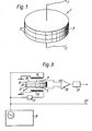
- Figure 1 shows a perspective view of a magnetic sensor forming part of the device;
- Figure 2 is a perspective view of part of the device;
- Figure 3 is a schematic diagram of the whole of the device; and
- Figure 4 is vector diagram of magnetic fields in the region of the magnetic sensor in operation.
- Referring to Figure 1 the device includes a magnetic sensor 1 of a kind forming the subject of United Kingdom Patent Application No: 8705449. The sensor 1 comprises a planar circular disc of
piezoelectric material 3 sandwiched betwen two planar circular discs of electrically conductivemagnetostrictive material 5. The twodiscs 5 have the same radial dimensions as thedisc 3 and are positioned on the opposite main surfaces of thedisc 3, in register with thedisc 3. Thedisc 3 is polarised so that when subject to compression or tension in any direction parallel to its main surfaces it will generate a potential difference between its main surfaces. The twodiscs 5 also serve as electrodes of the sensor 1 and are provided withleads 7. - When the magnetic sensor 1 is subjected to a magnetic field directed parallel to its plane the
discs 5 will expand in the direction of the applied field and consequently stretch thedisc 3 in the same direction. A dc potential difference-is consequently generated between the main surfaces of thedisc 3 whose value is representative of the strength of the applied field. This potential difference may thus be applied to an electric circuit via theleads 7. - It will be appreciated that the sensor exhibits the same sensitivity in all directions parallel to its plane and thus exhibits an onmidirectional characteristic in this plane.
- Referring to Figures 2 and 3, the magnetic sensor 1 is subjected to a magnetic biassing field produced by an alternating current fed by a reference frequency generator 9 to two
coils coils - The phase of the alternating current fed to the
coil 13 is arranged to be out of phase by-rr/2 with the alternating current fed to thecoil 11. This is effected by the presence of the" /2phase shifter 17. The voltage between theleads 7 is fed via adifferential amplifier 19 to abandpass filter 21. As explained below, in operation the output of thebandpass filter 21 comprises a phase shited carrier at the same frequency as the reference frequency generator 9, amplitude modulated by a magnetic field applied to the sensor whose direction is to be determined. - The operation of the device when used as a magnetic compass to determine the direction of the magnetic meridian will now be explained in detail. For such the sensor 1 is placed with its plane horizontal.
- Referring to Figure 4, at any instant the total mangnetic field HT in the region of the plane of the sensor 1 will comprise a component Ho due to the horizontal component of the earth's magnetic field and a component h due to the alternating currents fed to the
coils 


- where Hox is the sub-component of No in the x direction;
- Hoy is the sub-component of Ho in the y direction;
- hx is the sub-component of h in the x direction,
- hy is the sub-component of h in the y direction;
- θ is the angle between the vector Ho and the x-axis;
- wt is the angle between the vector h and the x-axis;
- (Ho is the modulus or magnitude of the vector Ho; and
- (h (is the modulus or magnitude of the vector h. Substituting the results of equations (2) and (3) in equation (1):


- The magnitude of the potential difference generated between the
leads 7, is proportional to the magnetostrictive expansion of thediscs 5. The magnetostrictive expansion of thediscs 5 is proportional to the square of the magnitude of the magnetic field in the region of the sensor. It may therefore be written:
leads 7; and k is a constant of proportionality dependent upon the sensitivity of the matrials used to fabricate the sensor 1. - From equations (4) and (5):


- In equation (6) k(Ho\2 and k(h\2 are dc terms and will therefore be filtered out by the
bandpass filter 21. The output of Vout thebandpass filter 21 will therefore be given by:
coil 11 producing the component hx = (h\cos wt of the biassing magnetic field, as shown in Figures 2 and 4).. This phase shift θ is equal to the bearing of magnetic north from the direction of the axis of thecoil 11. The phase shift may be detected by utilising the output of thebandpass filter 21 and aphase reference signal 23, obtained from the reference frequency generator 9, in a phase detector or phase and gain meter (not shown). - It will be appreciated that whilst in the embodiment of the invention described by way of example the relationship defined in equation (5) is a square relationship, in other embodiments this relationship may be any other non-linear relationship such that the output voltage of the sensor contains a cos (wt - e) term.
- In the particular embodiment described by way of eample, this relationship exists by virtue of the fact that the applied magnetic field is non-linearly related to the radial deformation of the
magnetostrictive discs 5 and an output voltage proportional to the deformation is produced by a transducer means constituted by thepiexoelectric disc 3. However, in other devices according to the invention alternative forms of transducer means may be used. - For example, a fibre-optic measurement technique may be used wherein the transducer means comprises one or more turns of optical fibre wound around and bound to the circumference of a disc of magnetostrictive material. Upon radial deformation of the disc the circumference of the disc varies proportionally thus stretching the optical fibre.
- Accurate detection of the change in length of the optical fibre can be carried out by making the optical fibre one arm of an interferometer (for example a Mach-Zehnder interferometer). The output of the interferometer will be of the form Ho cos (wt - 6).
- Another alternative form of transducer means for measuring the deformation of a magnetostrictive disc is a strain-gauge having its resistive element wound around, but insulated from, the circumference of the disc.
- It is further pointed out that in devices in accordance with the invention wherein the magnetic sensor comprises at least one member of magnetrostrictive material and transducer means responsive to deformation of the magnetostrictive member, the or each magnetostrictive member is not necessarily in the form of a disc, as in the embodiment drescribed by way of example. For example, the or each magnetrostrictive member may alternatively be of annnular form.
Claims (8)
Applications Claiming Priority (2)
| Application Number | Priority Date | Filing Date | Title |
|---|---|---|---|
| GB868612351A GB8612351D0 (en) | 1986-05-21 | 1986-05-21 | Magnetic field detection indicating devices |
| GB8612351 | 1986-05-21 |
Publications (2)
| Publication Number | Publication Date |
|---|---|
| EP0246780A2 true EP0246780A2 (en) | 1987-11-25 |
| EP0246780A3 EP0246780A3 (en) | 1988-11-30 |
Family
ID=10598200
Family Applications (1)
| Application Number | Title | Priority Date | Filing Date |
|---|---|---|---|
| EP87304035A Ceased EP0246780A3 (en) | 1986-05-21 | 1987-05-06 | Magnetic field direction indicating devices |
Country Status (5)
| Country | Link |
|---|---|
| US (1) | US4866384A (en) |
| EP (1) | EP0246780A3 (en) |
| JP (1) | JPS62284276A (en) |
| CA (1) | CA1280167C (en) |
| GB (1) | GB8612351D0 (en) |
Cited By (1)
| Publication number | Priority date | Publication date | Assignee | Title |
|---|---|---|---|---|
| US4916393A (en) * | 1987-12-16 | 1990-04-10 | Commissariat A L'energie Atomique | Continuous vectorial magnetometer with capacitive magnetostriction pickup and gradiometer involving the application of this pickup |
Families Citing this family (6)
| Publication number | Priority date | Publication date | Assignee | Title |
|---|---|---|---|---|
| US4992776A (en) * | 1988-04-08 | 1991-02-12 | Crossfield Michael D | Antipilferage tags and their use |
| JPH0518750A (en) * | 1991-07-09 | 1993-01-26 | Takao Yamaguchi | Total-range inclined direction measuring device |
| US5488778A (en) * | 1994-01-14 | 1996-02-06 | Potter; Bronson | Electronic magnetometer and compass |
| US5675252A (en) * | 1995-06-19 | 1997-10-07 | Sqm Technology, Inc. | Composite structured piezomagnetometer |
| DE19903296A1 (en) | 1999-01-28 | 2000-08-24 | Bosch Gmbh Robert | Device and method for determining a magnetic field |
| US6580271B2 (en) * | 1999-07-20 | 2003-06-17 | Spinix Corporation | Magnetic field sensors |
Family Cites Families (17)
| Publication number | Priority date | Publication date | Assignee | Title |
|---|---|---|---|---|
| US2334593A (en) * | 1941-05-08 | 1943-11-16 | Gulf Research Development Co | Apparatus for measuring magnetic fields |
| US2474693A (en) * | 1945-01-31 | 1949-06-28 | Robert G Rowe | Magnetic field responsive device |
| GB709528A (en) * | 1951-01-24 | 1954-05-26 | Clevite Corp | A magnetostrictive and electromechanical transducer device |
| US3903610A (en) * | 1972-08-18 | 1975-09-09 | North Atlantic Industries | Apparatus for measuring magnetic field direction |
| DE2341984A1 (en) * | 1973-08-20 | 1975-03-06 | Krupp Gmbh | PROBE |
| US3909809A (en) * | 1973-12-17 | 1975-09-30 | Canadian Patents Dev | Magnetic bubble domain sensing device |
| US4030204A (en) * | 1974-03-18 | 1977-06-21 | Edwards Robert A | Remote indicating solid state magnetic sensor |
| US3959889A (en) * | 1974-11-29 | 1976-06-01 | Thomas Samuel M | Method and apparatus for determining a measured direction relative to an external magnetic direction |
| GB1565188A (en) * | 1978-05-06 | 1980-04-16 | Elliott Bros | Compasses |
| US4267640A (en) * | 1979-04-30 | 1981-05-19 | Rca Corporation | System for ascertaining magnetic field direction |
| JPS5784310A (en) * | 1980-11-13 | 1982-05-26 | Alps Electric Co Ltd | Direction sensing means |
| JPS58165071A (en) * | 1982-03-25 | 1983-09-30 | Furukawa Electric Co Ltd:The | Measurement of dc magnetic field |
| US4443731A (en) * | 1982-09-30 | 1984-04-17 | Butler John L | Hybrid piezoelectric and magnetostrictive acoustic wave transducer |
| US4587487A (en) * | 1982-11-22 | 1986-05-06 | Gould Inc. | Optical fiber magnetometer for measuring D.C. and low frequency fields |
| US4462165A (en) * | 1983-01-31 | 1984-07-31 | The Boeing Company | Three axis orientation sensor for an aircraft or the like |
| US4564289A (en) * | 1984-07-31 | 1986-01-14 | Geo-Centers, Inc. | Single mode optical fiber polarimetric stress sensor having optical common mode rejection |
| GB2188157B (en) * | 1986-03-10 | 1990-07-18 | Gec Avionics | Magnetic sensor arrangements |
-
1986
- 1986-05-21 GB GB868612351A patent/GB8612351D0/en active Pending
-
1987
- 1987-05-06 EP EP87304035A patent/EP0246780A3/en not_active Ceased
- 1987-05-11 US US07/048,247 patent/US4866384A/en not_active Expired - Fee Related
- 1987-05-18 JP JP62120993A patent/JPS62284276A/en active Pending
- 1987-05-20 CA CA000537537A patent/CA1280167C/en not_active Expired - Lifetime
Cited By (1)
| Publication number | Priority date | Publication date | Assignee | Title |
|---|---|---|---|---|
| US4916393A (en) * | 1987-12-16 | 1990-04-10 | Commissariat A L'energie Atomique | Continuous vectorial magnetometer with capacitive magnetostriction pickup and gradiometer involving the application of this pickup |
Also Published As
| Publication number | Publication date |
|---|---|
| CA1280167C (en) | 1991-02-12 |
| EP0246780A3 (en) | 1988-11-30 |
| JPS62284276A (en) | 1987-12-10 |
| US4866384A (en) | 1989-09-12 |
| GB8612351D0 (en) | 1986-09-17 |
Similar Documents
| Publication | Publication Date | Title |
|---|---|---|
| US5041785A (en) | Device for measuring a relative displacement of two objects, including a magnetic scale and two mutually perpendicular magnetic sensors which produce two independent phase displaced signals | |
| Patranabis | Sensors and tranducers | |
| US4674331A (en) | Angular rate sensor | |
| US4205267A (en) | High speed electrostatic voltmeter | |
| US3239754A (en) | Thin film magnetometer | |
| US4088027A (en) | Force balance servo accelerometer | |
| US4315214A (en) | Displacement sensor using a galvanomagnetic element positioned in a periodically inverted magnetic field | |
| EP0246780A2 (en) | Magnetic field direction indicating devices | |
| US3229530A (en) | Accelerometer | |
| US4232265A (en) | Device for measuring intensity of magnetic or electromagnetic fields using strain gauges mounted on ferromagnetic plates | |
| US4186324A (en) | Linear accelerometer with piezoelectric suspension | |
| US3321702A (en) | Magnetometer and electrometer utilizing vibrating reeds whose amplitude of vibration is a measure of the field | |
| US2946226A (en) | Accelerometers | |
| US3940688A (en) | Device for testing the magnetic properties of a magnetic material | |
| US4418480A (en) | Magnetic heading reference | |
| Bucholtz et al. | Recent developments in fiber optic magnetostrictive sensors | |
| EP0246781A2 (en) | Magnetic field direction indicating devices | |
| US4506221A (en) | Magnetic heading transducer having dual-axis magnetometer with electromagnet mounted to permit pivotal vibration thereof | |
| EP0065830A1 (en) | Magnetoresistive sensor arrangement | |
| JPS5856408B2 (en) | magnetic sensor | |
| US3262309A (en) | Strain gage | |
| JPH0358444B2 (en) | ||
| US855220A (en) | Electric meter. | |
| SU842651A1 (en) | Method of magnetic field measuring | |
| SU1138773A1 (en) | Device for registering difference of seismic displacements in two points |
Legal Events
| Date | Code | Title | Description |
|---|---|---|---|
| PUAI | Public reference made under article 153(3) epc to a published international application that has entered the european phase |
Free format text: ORIGINAL CODE: 0009012 |
|
| AK | Designated contracting states |
Kind code of ref document: A2 Designated state(s): FR GB IT |
|
| PUAL | Search report despatched |
Free format text: ORIGINAL CODE: 0009013 |
|
| AK | Designated contracting states |
Kind code of ref document: A3 Designated state(s): FR GB IT |
|
| 17P | Request for examination filed |
Effective date: 19890525 |
|
| 17Q | First examination report despatched |
Effective date: 19911119 |
|
| STAA | Information on the status of an ep patent application or granted ep patent |
Free format text: STATUS: THE APPLICATION HAS BEEN REFUSED |
|
| 18R | Application refused |
Effective date: 19930711 |
|
| RIN1 | Information on inventor provided before grant (corrected) |
Inventor name: OETZMANN, EMERSON HARDY |