EP0246779A1 - Echangeur de chaleur - Google Patents
Echangeur de chaleur Download PDFInfo
- Publication number
- EP0246779A1 EP0246779A1 EP87304023A EP87304023A EP0246779A1 EP 0246779 A1 EP0246779 A1 EP 0246779A1 EP 87304023 A EP87304023 A EP 87304023A EP 87304023 A EP87304023 A EP 87304023A EP 0246779 A1 EP0246779 A1 EP 0246779A1
- Authority
- EP
- European Patent Office
- Prior art keywords
- plate
- tubes
- tube
- heat exchanger
- tube plate
- Prior art date
- Legal status (The legal status is an assumption and is not a legal conclusion. Google has not performed a legal analysis and makes no representation as to the accuracy of the status listed.)
- Withdrawn
Links
Images

Classifications
-
- F—MECHANICAL ENGINEERING; LIGHTING; HEATING; WEAPONS; BLASTING
- F28—HEAT EXCHANGE IN GENERAL
- F28F—DETAILS OF HEAT-EXCHANGE AND HEAT-TRANSFER APPARATUS, OF GENERAL APPLICATION
- F28F9/00—Casings; Header boxes; Auxiliary supports for elements; Auxiliary members within casings
- F28F9/02—Header boxes; End plates
- F28F9/0229—Double end plates; Single end plates with hollow spaces
-
- F—MECHANICAL ENGINEERING; LIGHTING; HEATING; WEAPONS; BLASTING
- F28—HEAT EXCHANGE IN GENERAL
- F28F—DETAILS OF HEAT-EXCHANGE AND HEAT-TRANSFER APPARATUS, OF GENERAL APPLICATION
- F28F2225/00—Reinforcing means
Definitions
- This invention relates to heat exchangers and, in particular, to heat exchangers having a plurality of parallel, spaced tubes for heat exchange fluid, the tubes being assembled into a unit using a tube plate having holes for receiving the tubes, and the plate extending transverse to the axes of the tubes.
- An object of the invention is to provide an improved tube to tube plate assembly.
- a heat exchanger comprises parallel, spaced tubes, a tube plate apertured to receive the tubes and extending transverse to the axes of the tubes, and a supplementary plate apertured to receive at least one of the tubes, the supplementary plate having over a peripheral region a portion extending transversely of the plane of the plate and secured to the tube plate whereby the supplementary plate is spaced from and parallel to the tube plate and fits over the associated tube or tubes to reinforce the tube and tube plate connection.
- the peripheral region of the supplementary plate includes a flange portion which lies parallel to the tube plate and is secured thereto by, for example, welding.
- the apertures in the tube plate and in the supplementary plate are each conveniently formed with upstanding rims which project from the plates in the same direction as one another.
- the depths of the rims are preferably arranged to be less than the spacing between the tube plate and the supplementary plate.
- the supplementary plate is conveniently of generally rectangular shape in plan view and the peripheral region extends over one or more edges of the plate.
- a heat exchanger which consists of a header tank 10 defined by a header member 11 (only part of which is shown) and a tube plate 12 secured thereto by bolts 13 and including a gasket 14.
- Tubes 15 communicate with the tank space 10 and lie parallel to one another and at right angles to the tube plate 12.
- the tubes 15 are in this case of flattened elongate form.
- the tubes 15 pass through secondary heat exchange surfaces in the form of fins 16, in known manner.
- the tube plate 12 is formed with a plurality of apertures through which the tubes 15 pass to enter into the space 10 and it is arranged that a fluid passes along the tubes between the header tank 10 at the upper ends of the tubes and a further tank (not shown) at the opposite, lower ends of the tubes. A further fluid with which heat is to be exchanged passes over the fins 16 and over the exterior of the tubes 15.
- the apertures in the tube plate 12 are formed in a manner, for example by plunging, such that an upstanding lip is defined around each of the apertures.
- the connection between the tubes 15 and tube plate 12 comes under stress, particularly towards the outermost tubes, i.e. the tubes closest to the outer edges of the header tank. This is believed to be due, a ⁇ least in part, to the tube plate 12 acting as a diaphragm as the tubes expand and contract.
- the reinforcing plate 20 is arranged to define apertures for receiving the outermost rows of tubes 15 in certain regions of the array of tubes and, over the apertured area of the plate 20, the plate 20 is parallel to and spaced from the tube plate 12.
- the apertures in the plate 20 are formed in a similar manner to those in the tube plate 12 so that an upstanding lip is defined around each aperture, the lips being directed upwards and in the same direction as those of the tube plate 12.
- the plate 20 is secured to the tube plate 12 along at least one of its peripheral edges by forming the edge with a transversely-directed bend 21 and a flange 22.
- the flange 22 lies in contact with the tube plate 12 and is secured thereto by welding, preferably by spot welding at spaced positions longitudinally of the flange.
- a turned-over portion 23 has its free end closely adjacent the surface of the tube plate 12.
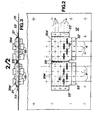
- Figs. 2 and 3 shows a specific form of tube plate 12', tubes 15' and reinforcing plates 20A' and 20B'.
- lateral rows P of tubes 15' lie at right angles to the sides of a rectangular tube plate 12'.
- the tubes 15' also lie in longitudinal rows R lying parallel to said sides, and at opposite ends of the rows R are arranged the reinforcing plates 20A' and 20B'.
- Fig. 2 only one end of the assembly is shown.
- the plates 20A I and 20B I take similar forms and each receive six of the rows P of tubes 15' through apertures aligned with apertures in the tube plate 12'.
- the plates 20A' and 20B I together receive all the tubes across the longitudinal rows R over said six lateral rows P.
- Each plate 20A' and 20B' is of generally rectangular shape and has a transverse bend 21' and flange 22' along two of its peripheral edges, the flanges 22' being secured to the tube plate 12' by welding as described in relation to Fig. 1.
- the plates each have a turned over portion 23' along another peripheral edge, the portions 23' lying closely adjacent one another.
- Figs. 4, 5 and 6 show a reinforcing plate 20'of Figs. 2 and 3 as a separate element before assembly with the tube plate 12'.
- connection of the tubes to the tube plate and to the reinforcing plate are enhanced by soldering, for example by dipping the assembled unit into solder.
- the tube to tube plate connection may be reinforced with different configurations of reinforcing plate.
- the reinforcement plate may receive all the tubes in an array.
- each reinforcing plate 20' with one or more V-shaped grooves or corrugations, the apex of the V being in contact with the tube plate 12' when assembled.
- Each corrugation extends between two or more of the rows P and serves to additionally reinforce and support the tube to tube plate connection.
Landscapes
- Engineering & Computer Science (AREA)
- Heat-Exchange Devices With Radiators And Conduit Assemblies (AREA)
- Physics & Mathematics (AREA)
- Thermal Sciences (AREA)
- Mechanical Engineering (AREA)
- General Engineering & Computer Science (AREA)
- Details Of Heat-Exchange And Heat-Transfer (AREA)
Applications Claiming Priority (2)
| Application Number | Priority Date | Filing Date | Title |
|---|---|---|---|
| GB8612517A GB8612517D0 (en) | 1986-05-22 | 1986-05-22 | Heat exchanger |
| GB8612517 | 1986-05-22 |
Publications (1)
| Publication Number | Publication Date |
|---|---|
| EP0246779A1 true EP0246779A1 (fr) | 1987-11-25 |
Family
ID=10598299
Family Applications (1)
| Application Number | Title | Priority Date | Filing Date |
|---|---|---|---|
| EP87304023A Withdrawn EP0246779A1 (fr) | 1986-05-22 | 1987-05-05 | Echangeur de chaleur |
Country Status (2)
| Country | Link |
|---|---|
| EP (1) | EP0246779A1 (fr) |
| GB (1) | GB8612517D0 (fr) |
Cited By (8)
| Publication number | Priority date | Publication date | Assignee | Title |
|---|---|---|---|---|
| EP0791796A1 (fr) * | 1996-02-26 | 1997-08-27 | MAGNETI MARELLI CLIMATIZZAZIONE S.r.l. | Condenseur pour systèmes de conditionnement d'air de véhicules |
| FR2746178A1 (fr) * | 1996-03-18 | 1997-09-19 | Valeo Thermique Moteur Sa | Echangeur de chaleur a collecteur et faisceau de tubes a ailettes |
| DE19734690C2 (de) * | 1997-08-11 | 2000-02-17 | Modine Mfg Co | Wärmetauscher, beispielsweise luftgekühlter Ladeluftkühler |
| DE19858325A1 (de) * | 1998-12-17 | 2000-06-29 | Behr Gmbh & Co | Wärmeübertrageranordnung für ein Kraftfahrzeug |
| WO2007137866A1 (fr) * | 2006-06-01 | 2007-12-06 | Behr Gmbh & Co. Kg | Échangeur thermique, notamment refroidisseur d'air de suralimentation, à fond tubulaire renforcé |
| EP2273227A3 (fr) * | 2009-07-10 | 2014-02-12 | Behr Industry GmbH & Co. KG | Echangeur thermique, notamment pour un moteur à combustion |
| EP2871437A1 (fr) * | 2013-11-08 | 2015-05-13 | Delphi Automotive Systems Luxembourg SA | Échangeur de chaleur |
| US11073345B2 (en) | 2018-10-31 | 2021-07-27 | Hanon Systems | Heat exchanger header with stiffening element |
Citations (7)
| Publication number | Priority date | Publication date | Assignee | Title |
|---|---|---|---|---|
| GB191175A (en) * | 1921-10-11 | 1923-01-11 | Heenan & Froude Ltd | Improvements in apparatus for transferring heat between air or gases and liquids |
| US1510807A (en) * | 1920-10-08 | 1924-10-07 | American Radiator Co | Radiator |
| GB790704A (en) * | 1955-08-16 | 1958-02-12 | Serck Radiators Ltd | Tubular heat exchange apparatus |
| US2950092A (en) * | 1957-11-01 | 1960-08-23 | Carrier Corp | Heat exchange construction |
| GB904498A (en) * | 1960-02-08 | 1962-08-29 | Borg Warner | Heat exchanger and method of making same |
| GB2086561A (en) * | 1980-10-23 | 1982-05-12 | Chausson Usines Sa | Heat exchanger with tubes and fins and tube plates mechanically assembled |
| JPS60105895A (ja) * | 1983-11-14 | 1985-06-11 | Nippon Denso Co Ltd | 熱交換器 |
-
1986
- 1986-05-22 GB GB8612517A patent/GB8612517D0/en active Pending
-
1987
- 1987-05-05 EP EP87304023A patent/EP0246779A1/fr not_active Withdrawn
Patent Citations (7)
| Publication number | Priority date | Publication date | Assignee | Title |
|---|---|---|---|---|
| US1510807A (en) * | 1920-10-08 | 1924-10-07 | American Radiator Co | Radiator |
| GB191175A (en) * | 1921-10-11 | 1923-01-11 | Heenan & Froude Ltd | Improvements in apparatus for transferring heat between air or gases and liquids |
| GB790704A (en) * | 1955-08-16 | 1958-02-12 | Serck Radiators Ltd | Tubular heat exchange apparatus |
| US2950092A (en) * | 1957-11-01 | 1960-08-23 | Carrier Corp | Heat exchange construction |
| GB904498A (en) * | 1960-02-08 | 1962-08-29 | Borg Warner | Heat exchanger and method of making same |
| GB2086561A (en) * | 1980-10-23 | 1982-05-12 | Chausson Usines Sa | Heat exchanger with tubes and fins and tube plates mechanically assembled |
| JPS60105895A (ja) * | 1983-11-14 | 1985-06-11 | Nippon Denso Co Ltd | 熱交換器 |
Non-Patent Citations (1)
| Title |
|---|
| PATENT ABSTRACTS OF JAPAN, vol. 9, no. 256 (M-421)[1979], 15th October 1985; & JP-A-60 105 895 (NIPPON DENSO K.K.) 11-06-1985 * |
Cited By (9)
| Publication number | Priority date | Publication date | Assignee | Title |
|---|---|---|---|---|
| EP0791796A1 (fr) * | 1996-02-26 | 1997-08-27 | MAGNETI MARELLI CLIMATIZZAZIONE S.r.l. | Condenseur pour systèmes de conditionnement d'air de véhicules |
| FR2746178A1 (fr) * | 1996-03-18 | 1997-09-19 | Valeo Thermique Moteur Sa | Echangeur de chaleur a collecteur et faisceau de tubes a ailettes |
| DE19734690C2 (de) * | 1997-08-11 | 2000-02-17 | Modine Mfg Co | Wärmetauscher, beispielsweise luftgekühlter Ladeluftkühler |
| DE19858325A1 (de) * | 1998-12-17 | 2000-06-29 | Behr Gmbh & Co | Wärmeübertrageranordnung für ein Kraftfahrzeug |
| DE19858325B4 (de) * | 1998-12-17 | 2009-01-15 | Behr Gmbh & Co. Kg | Wärmeübertrageranordnung für ein Kraftfahrzeug |
| WO2007137866A1 (fr) * | 2006-06-01 | 2007-12-06 | Behr Gmbh & Co. Kg | Échangeur thermique, notamment refroidisseur d'air de suralimentation, à fond tubulaire renforcé |
| EP2273227A3 (fr) * | 2009-07-10 | 2014-02-12 | Behr Industry GmbH & Co. KG | Echangeur thermique, notamment pour un moteur à combustion |
| EP2871437A1 (fr) * | 2013-11-08 | 2015-05-13 | Delphi Automotive Systems Luxembourg SA | Échangeur de chaleur |
| US11073345B2 (en) | 2018-10-31 | 2021-07-27 | Hanon Systems | Heat exchanger header with stiffening element |
Also Published As
| Publication number | Publication date |
|---|---|
| GB8612517D0 (en) | 1986-07-23 |
Similar Documents
| Publication | Publication Date | Title |
|---|---|---|
| EP0198581B1 (fr) | Echangeur | |
| US4881594A (en) | Header plate for pressure vessels, heat exchangers and the like | |
| US5174372A (en) | Heat exchanger with a plurality of ranges of tubes, in particular for a motor vehicle | |
| US4653581A (en) | Plate type heat exchanger | |
| US4688631A (en) | Plate heat exchanger | |
| EP0314261B1 (fr) | Assemblages à structure en nid d'abeille | |
| US4359088A (en) | Steam generator tube supports | |
| EP0147453B1 (fr) | Montage de joint d'etancheite pour un echangeur de chaleur a plaques | |
| EP0431917A1 (fr) | Duplex échangeur de chaleur | |
| CA1148933A (fr) | Support pour tubes d'echangeur de chaleur | |
| CA1094900A (fr) | Support pour tubes d'echangeur de chaleur | |
| FI78982C (fi) | Vaermevaexlare. | |
| EP0246779A1 (fr) | Echangeur de chaleur | |
| US5868198A (en) | Header pipes for heat exchanger | |
| US4625793A (en) | Header for a heat exchanger | |
| US5894884A (en) | Liquid filled cooling fin with reinforcing ribs | |
| JPH06174393A (ja) | 熱交換器 | |
| EP0415584B1 (fr) | Evaporateur de type empilé | |
| US20030131979A1 (en) | Oil cooler | |
| GB2130356A (en) | Header for a heat exchanger | |
| US5259449A (en) | Heat exchanger assembly III | |
| KR100511380B1 (ko) | 험프형플레이트핀열교환기 | |
| KR102109523B1 (ko) | 열교환기 판 및 판 열교환기 | |
| EP0179381A1 (fr) | Eléments d'échangeur de chaleur et méthode de fabrication | |
| US4019572A (en) | Radiator assembly for fluid filled electrical apparatus |
Legal Events
| Date | Code | Title | Description |
|---|---|---|---|
| PUAI | Public reference made under article 153(3) epc to a published international application that has entered the european phase |
Free format text: ORIGINAL CODE: 0009012 |
|
| AK | Designated contracting states |
Kind code of ref document: A1 Designated state(s): DE FR GB |
|
| STAA | Information on the status of an ep patent application or granted ep patent |
Free format text: STATUS: THE APPLICATION IS DEEMED TO BE WITHDRAWN |
|
| 18D | Application deemed to be withdrawn |
Effective date: 19880526 |
|
| RIN1 | Information on inventor provided before grant (corrected) |
Inventor name: DAVENPORT, CHRISTOPHER JOHN |