EP0246691B1 - Device for measuring the transmitting damping of an optical fibre - Google Patents
Device for measuring the transmitting damping of an optical fibre Download PDFInfo
- Publication number
- EP0246691B1 EP0246691B1 EP87200853A EP87200853A EP0246691B1 EP 0246691 B1 EP0246691 B1 EP 0246691B1 EP 87200853 A EP87200853 A EP 87200853A EP 87200853 A EP87200853 A EP 87200853A EP 0246691 B1 EP0246691 B1 EP 0246691B1
- Authority
- EP
- European Patent Office
- Prior art keywords
- fibre
- test
- optical
- face
- launching
- Prior art date
- Legal status (The legal status is an assumption and is not a legal conclusion. Google has not performed a legal analysis and makes no representation as to the accuracy of the status listed.)
- Expired - Lifetime
Links
- 239000013307 optical fiber Substances 0.000 title claims description 13
- 238000013016 damping Methods 0.000 title description 6
- 239000000835 fiber Substances 0.000 claims description 51
- 238000000034 method Methods 0.000 claims description 22
- 230000005540 biological transmission Effects 0.000 claims description 19
- 230000003287 optical effect Effects 0.000 claims description 19
- 238000001228 spectrum Methods 0.000 claims description 3
- 238000005259 measurement Methods 0.000 description 12
- 230000000694 effects Effects 0.000 description 4
- 230000008878 coupling Effects 0.000 description 2
- 238000010168 coupling process Methods 0.000 description 2
- 238000005859 coupling reaction Methods 0.000 description 2
- 230000004913 activation Effects 0.000 description 1
- 230000000052 comparative effect Effects 0.000 description 1
- 230000001419 dependent effect Effects 0.000 description 1
- 230000007774 longterm Effects 0.000 description 1
- 230000010287 polarization Effects 0.000 description 1
- 230000001105 regulatory effect Effects 0.000 description 1
- 230000007704 transition Effects 0.000 description 1
Images
Classifications
-
- G—PHYSICS
- G01—MEASURING; TESTING
- G01M—TESTING STATIC OR DYNAMIC BALANCE OF MACHINES OR STRUCTURES; TESTING OF STRUCTURES OR APPARATUS, NOT OTHERWISE PROVIDED FOR
- G01M11/00—Testing of optical apparatus; Testing structures by optical methods not otherwise provided for
- G01M11/30—Testing of optical devices, constituted by fibre optics or optical waveguides
- G01M11/33—Testing of optical devices, constituted by fibre optics or optical waveguides with a light emitter being disposed at one fibre or waveguide end-face, and a light receiver at the other end-face
Definitions
- the invention relates to a method for measuring the transmission loss of an optical waveguide (test fiber), in which from an optical transmitter via a transmit fiber from the output surface of the transmit optical fiber emitting light with predetermined light output in the input surface of the substantially coaxial to Transmit LWL aligned test fiber and at which output light of the test fiber is received with an optical detector, wherein the intensity of the output light of the test fiber is determined.
- test fiber optical waveguide
- the fiber to be tested is coupled to the transmitting fiber via a free-beam optic.
- An LED serves as the transmission light source.
- Free-beam optics require a lot of adjustment to be able to bundle the transmitted light beam as precisely as possible in the test fiber.
- the invention has for its object to improve the accuracy and reproducibility of damping measurements.
- the solution is achieved by placing a beam-expanding element, such as in particular a defocusing gradient lens, between the output surface of the transmission fiber and the input surface of the test fiber, or by the input surface of the test fiber and the output surface of the transmission fiber in a clearance of more than 100 microns from each other.
- a beam-expanding element such as in particular a defocusing gradient lens
- the light emerging from the transmitting optical fiber is coupled into the coaxially aligned measuring optical fiber by means of beam expansion, tolerance-related errors in the coaxiality can only have a greatly reduced and practically negligible effect.
- tolerance-related errors in the coaxiality can only have a greatly reduced and practically negligible effect.
- the remaining received light component e.g. when using an LED as a transmission light source, it is completely sufficient to be able to receive sufficiently large measurement signals with conventional optical detectors, for example with a photodiode.
- the beam expansion is achieved in a particularly simple manner in that the beam expansion means consist of a holding device for the test fiber, by means of which the input surface of the test fiber can be aligned at a distance of more than 100 .mu.m from the output surface of the transmitting fiber.
- the beam expansion means consist of a holding device for the test fiber, by means of which the input surface of the test fiber can be aligned at a distance of more than 100 .mu.m from the output surface of the transmitting fiber.
- a distance of 500-600 ⁇ m has proven to be particularly advantageous. This results in a good compromise between achievable accuracy and the remaining light intensity in the test fiber.
- a selected distance should be set approximately exactly with each new measurement. This is advantageously done in that a reference surface of the device is provided, to which the test fiber can be aligned axially.
- the optical transmitter contains an incoherent light source, in particular an LED, and that a narrow-band optical filter element, in particular a bandpass or interference filter, is arranged so that the transmission beam of the light source on the route to the transmission fiber through the Filter element is conductive.
- the optical transmission power of the LED should be stabilized. This is possible with simple means, so that no changes in the transmitted wavelengths or light outputs occur even with temperature fluctuations or long-term effects.
- An incoherent light source is preferable because then, as with lasers, noise effects due to reflection, mode noise and polarization cannot have a distorting effect on the measurement results.
- a measurement at practically a single wavelength with a narrow bandwidth as with a laser is made possible by the activation of a passive wavelength-selective element. This can be arranged directly behind an LED, but also at any other point in front of the optical detector. Since extremely narrow-band transmission light is available in this way, it is possible to measure attenuation values at a precisely defined wavelength. In this case, unlike in a broadband measuring method, attenuation values are not obtained which are defined as values averaged over a certain wavelength range. Rather, several measurements can be carried out at different closely adjacent wavelengths in the wavelength range of interest of a test optical fiber, so that the wavelength dependence of the attenuation can be recognized.
- the highest attenuation occurs at the shortest wavelength that is permitted for the FO according to the specification.
- This damping value which is important in practice, can also be reliably determined, in particular if a particularly precise narrow-band filter is used, the center wavelength of which deviates from the target value by less than 3 nm.
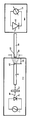
- the figure shows the relative assignment of the essential components of a device for carrying out the method according to the invention required for measuring the transmission loss of a test optical fiber.
- the device for measuring the transmission loss of the test fiber 8 shown in the figure consists of the transmitter 7 and the receiver 9, which usually has a photodiode 10 and an electrical display element 11 contains, the display of which is dependent on the light intensity that passes from the test fiber 8 to the photodiode 10.
- an LED 2 is arranged as an incoherent transmission light source, which is controlled and regulated via a power supply circuit 1 such that the intensity and / or the center wavelength of the spectrum of the transmitted light 14 has a constant predetermined value.
- a power supply circuit 1 such that the intensity and / or the center wavelength of the spectrum of the transmitted light 14 has a constant predetermined value.
- An optical bandpass filter or an interference filter is particularly suitable.
- the input surface 13 of the test fiber 8 is at a distance 5 of 500-600 ⁇ m away from the output surface 12 of the transmission fiber 4, so that the beam diameter is widened to a diameter 6 according to the dashed lines in the plane of the input surface 13.
- Errors in the coaxiality of the transmission fiber 4 and the test fiber 8 and the spacing of their surfaces 12 and 13 have no noticeable effect on the display of the display element 11, even if they are of the order of a few ⁇ m.
- the level of the light intensity guided in the test fiber is always a constant component of the predetermined and known light intensity of the LED 2, so that after a single calibration of the transmitter 7, the input level of the test fiber is always known. A single measurement is therefore sufficient to determine the transmission loss of the test fiber 8 without the need for comparative measurements on shortened sections of the test fiber 8.
- the space between the surfaces 12 and 13 is preferably an air space, but this space could also be filled with another homogeneous, optically transparent medium.
Landscapes
- Physics & Mathematics (AREA)
- Optics & Photonics (AREA)
- Chemical & Material Sciences (AREA)
- Analytical Chemistry (AREA)
- General Physics & Mathematics (AREA)
- Optical Couplings Of Light Guides (AREA)
- Testing Of Optical Devices Or Fibers (AREA)
- Photometry And Measurement Of Optical Pulse Characteristics (AREA)
- Light Guides In General And Applications Therefor (AREA)
Description
Die Erfindung bezieht sich auf ein Verfahren zur Messung der Durchgangsdämpfung eines Lichtwellenleiters (Prüf-LWL), bei welchem von einem optischen Sender über einen Sende-LWL aus der Ausgangsfläche des Sende-LWL ausgehendes Sendelicht mit vorgegebener Lichtleistung in die Eingangsfläche des im wesentlichen koaxial zum Sende-LWL ausgerichteten Prüf-LWL gerichtet wird und bei welchem Ausgangslicht des Prüf-LWL mit einem optischen Detektor empfangen wird, wobei die Intensität des Ausgangslichts des Prüf-LWL ermittelt wird.The invention relates to a method for measuring the transmission loss of an optical waveguide (test fiber), in which from an optical transmitter via a transmit fiber from the output surface of the transmit optical fiber emitting light with predetermined light output in the input surface of the substantially coaxial to Transmit LWL aligned test fiber and at which output light of the test fiber is received with an optical detector, wherein the intensity of the output light of the test fiber is determined.
Ein derartiges Verfahren ist durch Optical and Quantum Electronics 10 (1978), S. 253-265 bekannt. Dabei wird der zu prüfende LWL über eine Freistrahloptik an die Sende-LWL angekoppelt. Als Sendelichtquelle dient eine LED. Eine Freistrahloptik erfordert einen hohen Justieraufwand, um den Sendelichtstrahl möglichst genau in den Prüf-LWL bündeln zu können.Such a method is known from Optical and Quantum Electronics 10 (1978), pp. 253-265. The fiber to be tested is coupled to the transmitting fiber via a free-beam optic. An LED serves as the transmission light source. Free-beam optics require a lot of adjustment to be able to bundle the transmitted light beam as precisely as possible in the test fiber.
Durch Steckvorrichtungen hergestellte Verbindungen von Lichtwellenleitern weisen keine konstant bleibenden Übergangsdämpfungen auf. Der je nach geometrischer Toleranzlage der Achszuordnungen beider LWL sich ergebenden Dämpfungswert schwankt erheblich. Beim Ersatz einer Freistrahloptik durch eine Steckverbindung sind deshalb die Meßwerte der Dämpfungen nicht reproduzierbar. Sie schwanken um die Streubreite der Dämpfung der Steckverbindungen.Connections of optical fibers made by plug devices do not have constant transition attenuation. The resulting damping value varies considerably depending on the geometrical tolerance of the axis assignments of both fiber optic cables. When replacing a free beam optics with a plug connection, the measured values of the damping are therefore not reproducible. They fluctuate around the spread of the damping of the plug connections.
Ein eingangs genanntes Verfahren ist auch durch die EP-A-0150434 bekannt. Dort wird eine genaue koaxiale Ausrichtung der zu koppelnden LWL verlangt. Die Enden der LWL sollen verschweißt oder über ein "index-matching"-Mittel gekoppelt werden.A method mentioned at the outset is also known from EP-A-0150434. There, an exact coaxial alignment of the FO to be coupled is required. The ends of the fiber optic cables are to be welded or coupled using an "index matching" means.
Der Erfindung liegt die Aufgabe zugrunde, die Genauigkeit und Reproduzierbarkeit von Dämpfungsmessungen zu verbessern.
Die Lösung gelingt dadurch, daß zwischen der Ausgangsfläche des Sende-LWL und der Eingangsfläche des Prüf-LWL ein strahlaufweitendes Element, wie insbesondere eine defokussierende Gradientenlinse angeordnet wird, oder dadurch, daß die Eingangssfläche des Prüf-LWL und die Ausgansfläche des Sende-LWL in einem Freiabstand von mehr als 100 µm zueinander angeordnet werden.The invention has for its object to improve the accuracy and reproducibility of damping measurements.
The solution is achieved by placing a beam-expanding element, such as in particular a defocusing gradient lens, between the output surface of the transmission fiber and the input surface of the test fiber, or by the input surface of the test fiber and the output surface of the transmission fiber in a clearance of more than 100 microns from each other.
Wenn das aus dem Sende-LWL austretende Licht über Mittel zur Strahlaufweitung in den koaxial ausgerichteten Meß-LWL eingekoppelt wird, können sich toleranzbedingte Fehler der Koaxialität nur noch in stark reduziertem und praktisch vernachlässigbarem Ausmaß auswirken. Zwar wird in den Meß-LWL dann auch nur eine verringerte Lichtleistung eingekoppelt, jedoch ist der verbleibende empfangene Lichtanteil, z.B. bei Verwendung einer LED als Sende-Lichtquelle, völlig ausreichend, um mit üblichen optischen Detektoren, beispielsweise mit einer Photodiode, genügend große Meßsignale empfangen zu können.If the light emerging from the transmitting optical fiber is coupled into the coaxially aligned measuring optical fiber by means of beam expansion, tolerance-related errors in the coaxiality can only have a greatly reduced and practically negligible effect. Although only a reduced light output is then coupled into the measurement optical fiber, the remaining received light component, e.g. when using an LED as a transmission light source, it is completely sufficient to be able to receive sufficiently large measurement signals with conventional optical detectors, for example with a photodiode.
Mittels den erfindungsgemäßen Verfahren werden Meßergebnisse mit einer solchen Genauigkeit erreicht, wie sie bisher nur mit der sogenannten Abschneidemethode erzielbar war, bei welcher nach einer ersten Messung eine zweite Vergleichsmessung an einem durch Abschneiden verkürzten Ende des Prüf-LWL durchgeführt werden mußte. Darauf kann man erfindungsgemäß verzichten, da mit hinreichender Genauigkeit davon ausgegangen werden kann, daß die in den Prüf-LWL eingekoppelte Lichtleistung praktisch unabhängig von der zufälligen Toleranzlage der räumlichen Ankopplung hinreichend genau einen vorgegebenen Wert hat. In der Praxis ergaben sich Schwankungen von weniger als 0,1 dB.By means of the method according to the invention, measurement results are achieved with such an accuracy as was previously only possible with the so-called cut-off method, in which after a first measurement a second comparison measurement had to be carried out at an end of the test fiber that was shortened by cutting. This can be dispensed with according to the invention, since it can be assumed with sufficient accuracy that the light output coupled into the test optical fiber has a predetermined value practically independently of the random tolerance position of the spatial coupling. In practice, there were fluctuations of less than 0.1 dB.
Auf besonders einfache Weise erreicht man die Strahlaufweitung dadurch, daß die strahlaufweitenden Mittel aus einer Halteeinrichtung für den Prüf-LWL bestehen, mittels welcher die Eingangsfläche des Prüf-LWL mit einem Abstand von mehr als 100 um zur Ausgangsfläche des Sende-LWL ausrichtbar ist. Dabei wird von der Tatsache Gebrauch gemacht, daß sich ein in einem Lichtwellenleiter geführter Strahl aufweitet, sobald er den Lichtwellenleiter in ein homogenes Medium wie z.B. Luft verläßt.The beam expansion is achieved in a particularly simple manner in that the beam expansion means consist of a holding device for the test fiber, by means of which the input surface of the test fiber can be aligned at a distance of more than 100 .mu.m from the output surface of the transmitting fiber. Use is made of the fact that there is an optical waveguide guided beam expands as soon as it leaves the optical fiber in a homogeneous medium such as air.
Als besonders vorteilhaft hat sich ein Abstand von 500-600 um erwiesen. Dabei ergibt sich ein guter Kompromiß zwischen erzielbarer Genauigkeit und verbleibender Lichtintensität in dem Prüf-LWL.A distance of 500-600 μm has proven to be particularly advantageous. This results in a good compromise between achievable accuracy and the remaining light intensity in the test fiber.
Natürlich sollte ein gewählter Abstand bei jeder neuen Messung in etwa genau eingestellt werden. Das geschieht vorteilhaft dadurch, daß eine Bezugsfläche der Vorrichtung vorgesehen ist, zu welcher der Prüf-LWL axial ausrichtbar ist.Of course, a selected distance should be set approximately exactly with each new measurement. This is advantageously done in that a reference surface of the device is provided, to which the test fiber can be aligned axially.
Vorzugsweise ist weiterhin vorgesehen, daß der optische Sender eine inkohärente Lichtquelle, insbesondere eine LED enthält, und daß ein schmalbandiges optisches Filterelement insbesondere ein Bandpaß- oder Interferenzfilter, so angeordnet ist, daß der Sendestrahl der Lichtquelle auf der Strecke bis zum Sende-LWL durch das Filterelement leitbar ist. Dabei sollte die optische Sendeleistung der LED stabilisiert sein. Das ist mit einfachen Mitteln möglich, so daß auch bei Temperaturschwankungen oder Langzeitwirkungen keine Änderungen der gesendeten Wellenlängen oder Lichtleistungen auftreten.It is preferably further provided that the optical transmitter contains an incoherent light source, in particular an LED, and that a narrow-band optical filter element, in particular a bandpass or interference filter, is arranged so that the transmission beam of the light source on the route to the transmission fiber through the Filter element is conductive. The optical transmission power of the LED should be stabilized. This is possible with simple means, so that no changes in the transmitted wavelengths or light outputs occur even with temperature fluctuations or long-term effects.
Eine inkohärente Lichtquelle ist deshalb vorzuziehen, weil dann nicht wie bei Lasern Rauscheffekte durch Reflexion, Modenrauschen und Polarisation verfälschend auf die Meßergebnisse einwirken können. Eine Messung bei praktisch einer einzigen Wellenlänge mit einer schmalen Bandbreite wie bei einem Laser wird durch die Einschaltung eines passiven wellenlängenselektiven Elements ermöglicht. Dieses kann direkt hinter einer LED angeordnet sein, jedoch auch an beliebiger anderer Stelle vor dem optischen Detektor.
Da auf diese Weise extrem schmalbandiges Sendelicht verfügbar ist, ist es möglich, Dämpfungswerte bei einer exakt definierten Wellenlänge zu messen. Man erhält dann nicht, wie bei einem breitbandigeren Meßverfahren, nur solche Dämpfungswerte, die als über einen gewissen Wellenlängenbereich gemittelte Werte definiert sind. Vielmehr können im interessierenden Wellenlängenbereich eines Prüf-LWL mehrere Messungen bei verschiedenen eng benachbarten Wellenlängen durchgeführt werden, so daß die Wellenlängenabhängigkeit der Dämpfung erkennbar wird.An incoherent light source is preferable because then, as with lasers, noise effects due to reflection, mode noise and polarization cannot have a distorting effect on the measurement results. A measurement at practically a single wavelength with a narrow bandwidth as with a laser is made possible by the activation of a passive wavelength-selective element. This can be arranged directly behind an LED, but also at any other point in front of the optical detector.
Since extremely narrow-band transmission light is available in this way, it is possible to measure attenuation values at a precisely defined wavelength. In this case, unlike in a broadband measuring method, attenuation values are not obtained which are defined as values averaged over a certain wavelength range. Rather, several measurements can be carried out at different closely adjacent wavelengths in the wavelength range of interest of a test optical fiber, so that the wavelength dependence of the attenuation can be recognized.
Normalerweise tritt die höchste Dämpfung (worst-case) bei der kürzesten Wellenlänge auf, die für den LWL laut Spezifikation zugelassen ist. Auch diesen für die Praxis wichtigen Dämpfungswert kann man zuverlässig ermitteln, insbesondere dann, wenn ein besonders präzises schmalbandiges Filter verwendet wird, dessen Mittenwellenlänge um weniger als 3 nm vom Sollwert abweicht.Normally, the highest attenuation (worst-case) occurs at the shortest wavelength that is permitted for the FO according to the specification. This damping value, which is important in practice, can also be reliably determined, in particular if a particularly precise narrow-band filter is used, the center wavelength of which deviates from the target value by less than 3 nm.
Es hat sich gezeigt, daß bei einem erfindungsgemäßen Verfahren die Genauigkeit der Ankopplung eines Prüf-LWL wenig kritisch ist. Das gilt sowohl hinsichtlich der Koaxialität von Sende-LWL und Prüf-LWL als auch hinsichtlich deren axialen Abstandes.It has been shown that the accuracy of the coupling of a test fiber is not critical in a method according to the invention. This applies both with regard to the coaxiality of the transmission fiber-optic cable and the test fiber-optic cable as well as with regard to their axial spacing.
Insgesamt ergibt sich durch die Erfindung eine einfache und unkompliziert handhabbare genau messende Vorrichtung.Overall, the invention results in a simple and uncomplicated, precisely measuring device.
Die Erfindung wird anhand der Beschreibung eines schematisch in der Zeichnung dargestellten Ausführungsbeispiels näher erläutert.The invention is explained in more detail with reference to the description of an exemplary embodiment shown schematically in the drawing.
Die Figur zeigt die relative Zuordnung der zur Messung der Durchgangsdämpfung eines Prüf-LWL erforderlichen wesentlichen Bauelemente einer Vorrichtung zur Durchführung des erfindungsgemäßen Verfahrens.The figure shows the relative assignment of the essential components of a device for carrying out the method according to the invention required for measuring the transmission loss of a test optical fiber.
Die in der Figur dargestellte Vorrichtung zur Messung der Durchgangsdämpfung des Prüf-LWL 8 besteht aus dem Sender 7 und dem Empfänger 9, welcher üblicherweise eine Photodiode 10 und ein elektrisches Anzeigeelement 11 enthält, dessen Anzeige von der Lichtintensität abhängig ist, die aus dem Prüf-LWL 8 auf die Photodiode 10 gelangt.The device for measuring the transmission loss of the test fiber 8 shown in the figure consists of the transmitter 7 and the receiver 9, which usually has a photodiode 10 and an
Im Sender 7 ist eine LED 2 als inkohärente Sende-Lichtquelle angeordnet, welche über eine Stromversorgungsschaltung 1 derart gesteuert und geregelt wird, daß die Intensität und/oder die Mittenwellenlänge des Spektrums des gesendeten Lichts 14 einen konstanten vorgegebenen Wert hat. Von dem insbesondere mittleren Bereich des relativ breiten Wellenlängenspektrums der LED 2 wird praktisch nur eine Wellenlänge durch das Filterelement 3 in den Sende-LWL 4 hindurchgelassen. Besonders geeignet ist ein optisches Bandpaßfilter oder ein Interferenzfilter.In the transmitter 7, an LED 2 is arranged as an incoherent transmission light source, which is controlled and regulated via a power supply circuit 1 such that the intensity and / or the center wavelength of the spectrum of the transmitted light 14 has a constant predetermined value. Of the in particular middle region of the relatively broad wavelength spectrum of the LED 2, practically only one wavelength is let through the
Die Eingangsfläche 13 des Prüf-LWL 8 ist von der Ausgangsfläche 12 des Sende-LWL 4 um einen Abstand 5 von 500-600 um entfernt, so daß der Strahldurchmesser gemäß den gestrichelten Linien in der Ebene der Eingangsfläche 13 auf einen Durchmesser 6 aufgeweitet ist.The input surface 13 of the test fiber 8 is at a distance 5 of 500-600 μm away from the
Fehler der Koaxialität des Sende-LWL 4 und des Prüf-LWL 8 sowie der Abstände ihrer Flächen 12 und 13 wirken sich auf die Anzeige des Anzeigeelements 11 nicht merkbar aus, selbst wenn sie in der Größenordnung von einigen µm liegen. Der Pegel der in den Prüf-LWL geleiteten Lichtintensität ist stets ein konstanter Anteil der vorgegebenen und bekannten Lichtintensität der LED 2, so daß nach einmaliger Eichung des Senders 7 stets der Eingangspegel des Prüf-LWL bekannt ist. Für die Ermittlung der Durchgangsdämpfung des Prüf-LWL 8 genügt deshalb eine einzige Messung, ohne daß Vergleichsmessungen an gekürzten Abschnitten des Prüf-LWL 8 erforderlich sind.Errors in the coaxiality of the transmission fiber 4 and the test fiber 8 and the spacing of their
Vorzugsweise ist der Abstandsraum zwischen den Flächen 12 und 13 ein Luftraum, jedoch könnte dieser Raum auch mit einem anderen homogenen optisch durchlässigen Medium gefüllt sein.The space between the
Wenn eine schnellere Strahlaufweitung auf einer dann kürzeren Aufweitungsstrecke erwünscht ist, können spezielle bekannte Aufweitungselemente wie insbesondere defokussierende Gradientenlinsen zwischen den Flächen 12 und 13 vorgesehen werden.If a faster beam expansion on a then shorter expansion path is desired, special known expansion elements, such as defocusing gradient lenses in particular, can be provided between the
Claims (9)
- A method of measuring the transmission loss of an optical fibre (test fibre 8), in which method use is made of an optical transmitter (7) to couple light issuing from the exit face (12) of the launching fibre (4) into the entrance face (13) of the test fibre (8) at a predetermined light power, which test fibre is substantially coaxially arranged relative to the launching fibre (4), and in which method light issuing from the test fibre (8) is received by an optical detector (9) to determine its intensity, characterized in that the entrance face (13) of the test fibre (8) and the exit face (12) of the launching fibre (4) are arranged relative to each other with a face interspace of more than 100 µm.
- A method as claimed in Claim 1, characterized in that the entrance face (13) of the test fibre (8) and the exit face (12) of the launching fibre (4) are arranged relative to each other with an interspace of 500 to 600 µm.
- A method as claimed in Claims 1 or 2, characterized in that the entrance face (13) of the fibre under test (8) is aligned with respect to a reference face of a device used to carry out the method.
- A method as claimed in Claim 3, characterized in that the reference face of the device is formed by a connector portion.
- A method of measuring the transmission loss of an optical fibre (test fibre), in which method use is made of an optical transmitter (7) to couple light issuing from the exit face (12) of the launching fibre (4) into the entrance face (13) of the test fibre (8) at a predetermined light power, which test fibre is substantially coaxially arranged relative to the launching fibre (4), and in which method light issuing from the test fibre (8) is received by an optical detector (9) to determine its intensity, characterized in that a beam-expansion element, notably a defocussing gradient lens, is arranged between the exit face of the launching fibre (4) and the entrance face (13) of the fibre under test (8).
- A method as claimed in one of the Claims 1 to 5, characterized in that an incoherent light source, notably a LED (2), is used as the optical transmitter (7) whose beam is passed through a narrow band optical filer element, notably a bandpass or interference filter (3), arranged in the path to the optical detector (9).
- A method as claimed in Claim 5, characterized in that the optical transmission power of the LED is stabilized.
- A method as claimed in any one of the Claims 5 or 6, characterized in that the central wavelength of the spectrum emitted by the light source (2) is stabilized.
- A method as claimed in one of the Claims 6 to 8, characterized in that the central wavelength of the filter deviates less than + or - 3 nm from the specified value.
Applications Claiming Priority (2)
| Application Number | Priority Date | Filing Date | Title |
|---|---|---|---|
| DE19863616841 DE3616841A1 (en) | 1986-05-17 | 1986-05-17 | DEVICE FOR MEASURING THE CONTINUOUS DAMPING OF A LIGHTWAVE GUIDE |
| DE3616841 | 1986-05-17 |
Publications (3)
| Publication Number | Publication Date |
|---|---|
| EP0246691A2 EP0246691A2 (en) | 1987-11-25 |
| EP0246691A3 EP0246691A3 (en) | 1989-09-06 |
| EP0246691B1 true EP0246691B1 (en) | 1992-08-12 |
Family
ID=6301170
Family Applications (1)
| Application Number | Title | Priority Date | Filing Date |
|---|---|---|---|
| EP87200853A Expired - Lifetime EP0246691B1 (en) | 1986-05-17 | 1987-05-11 | Device for measuring the transmitting damping of an optical fibre |
Country Status (3)
| Country | Link |
|---|---|
| EP (1) | EP0246691B1 (en) |
| JP (1) | JPS6324138A (en) |
| DE (2) | DE3616841A1 (en) |
Families Citing this family (7)
| Publication number | Priority date | Publication date | Assignee | Title |
|---|---|---|---|---|
| DE4009160C2 (en) * | 1990-03-22 | 1993-11-18 | Wandel & Goltermann | Optical measuring device for a multimode fiber |
| DE4430512C2 (en) * | 1994-08-27 | 2000-06-29 | Bosch Gmbh Robert | Device for connecting a reinforcing fiber |
| DE19645542A1 (en) * | 1996-11-05 | 1998-05-07 | Lucent Tech Network Sys Gmbh | Optical signal transfer system especially for messages |
| DE10144339B4 (en) * | 2001-09-10 | 2017-07-27 | Lisa Dräxlmaier GmbH | Test device for determining the attenuation of an optical waveguide to be tested |
| DE10322188B4 (en) * | 2003-05-16 | 2008-08-21 | Lisa Dräxlmaier GmbH | Light output control device with mode mixer |
| DE102005060460B4 (en) * | 2005-12-17 | 2012-10-18 | Schäfer Werkzeug- und Sondermaschinenbau GmbH | Method for controlling optical waveguides |
| DE202013103148U1 (en) | 2013-07-15 | 2014-10-16 | Walo - Tl Gmbh | Apparatus for testing an optical fiber |
Family Cites Families (9)
| Publication number | Priority date | Publication date | Assignee | Title |
|---|---|---|---|---|
| JPS50114235A (en) * | 1974-02-15 | 1975-09-08 | ||
| JPS57116234A (en) * | 1981-01-12 | 1982-07-20 | Nippon Telegr & Teleph Corp <Ntt> | Measuring method for photo loss |
| JPS5855969A (en) * | 1981-09-29 | 1983-04-02 | 東芝ライテック株式会社 | Display unit |
| JPS5975134A (en) * | 1982-10-22 | 1984-04-27 | Nippon Telegr & Teleph Corp <Ntt> | Light source for measuring light loss of optical fiber |
| JPS5988070A (en) * | 1982-11-11 | 1984-05-21 | Besuto Kogyo Kk | Preparation of laver sheet |
| DE3327668A1 (en) * | 1983-07-30 | 1985-02-07 | Udo Dr Ing Unrau | Arrangement for selective mode excitation or mode analysis in graded-index fibres |
| US4556314A (en) * | 1983-08-31 | 1985-12-03 | At&T Bell Laboratories | Dispersion determining method and apparatus |
| US4629316A (en) * | 1983-10-25 | 1986-12-16 | Raychem Corporation | Attenuation across optical fiber splice |
| JPS60142228A (en) * | 1983-12-29 | 1985-07-27 | Sumitomo Electric Ind Ltd | Measuring method of optical fiber characteristics |
-
1986
- 1986-05-17 DE DE19863616841 patent/DE3616841A1/en not_active Withdrawn
-
1987
- 1987-05-11 DE DE8787200853T patent/DE3781022D1/en not_active Expired - Lifetime
- 1987-05-11 EP EP87200853A patent/EP0246691B1/en not_active Expired - Lifetime
- 1987-05-14 JP JP62116011A patent/JPS6324138A/en active Pending
Non-Patent Citations (1)
| Title |
|---|
| Wolfgang Glaser: Lichtleitertecknik, eine Einführung, VEB-Verlag Technik, Berlin 1981 * |
Also Published As
| Publication number | Publication date |
|---|---|
| EP0246691A3 (en) | 1989-09-06 |
| DE3781022D1 (en) | 1992-09-17 |
| EP0246691A2 (en) | 1987-11-25 |
| JPS6324138A (en) | 1988-02-01 |
| DE3616841A1 (en) | 1987-11-19 |
Similar Documents
| Publication | Publication Date | Title |
|---|---|---|
| DE69628624T2 (en) | OTDR apparatus | |
| DE69318011T2 (en) | Optical coupler with optical mode mixer | |
| CH644975A5 (en) | OPTICAL FIBER DIRECTIONAL COUPLER AND THEIR USE IN A TRANSMITTER / RECEIVER. | |
| DE3605248C2 (en) | ||
| EP0053324B2 (en) | Optical branching device | |
| DE3409207A1 (en) | OPTICAL SENSOR | |
| DE2944977A1 (en) | OPTICAL WAVE FASHION MIXER | |
| DE4019980A1 (en) | TEMPERATURE SENSOR ARRANGEMENT DISTRIBUTED BY FIBER OPTICS | |
| EP0361588A1 (en) | Optical fibre sensor | |
| DE2752688C3 (en) | Optical transmitter of a device for measuring the attenuation of optical waves on optical transmission lines | |
| EP0297669B1 (en) | Method for measuring a reflected optical radiation | |
| EP0246691B1 (en) | Device for measuring the transmitting damping of an optical fibre | |
| DE69900660T2 (en) | Device with a dispersive fiber optic tap | |
| EP0380801A3 (en) | Process for determining the optical loss of optical fibres in reflected light | |
| CH680020A5 (en) | ||
| DE60001825T2 (en) | OPTICAL DEVICE WITH POLARIZATION-MAINTAINING FIBER | |
| DE4314031A1 (en) | Monitoring and protection device for optical-fibre cables (fibre-optic cables) | |
| DE2835491C3 (en) | Arrangement for measuring properties of optical fibers | |
| DE2739880C2 (en) | Device for locating faults in optical fibers or optical fiber cables | |
| DE2456293A1 (en) | Fault location in optical fibres or cables - uses light pulse generated by laser | |
| EP0208011B1 (en) | Light coupling device for the optical reflectometry | |
| DE3924185C1 (en) | Fibre=optic pressure sensor - has three=way coupler splitting incoming light for distribution to reference and sensor fibres for pressure diaphragm | |
| DE69931650T2 (en) | GENERATION OF AN ELECTROMAGNETIC IMPULSE SEQUENCE FOR THE TESTING OF FIBROUS FIBERS | |
| EP0073314A1 (en) | Transmission system for the multiple bidirectional use of an optical fibre | |
| DE19637885C2 (en) | Optical receiver with a fiber system with two inputs and one output |
Legal Events
| Date | Code | Title | Description |
|---|---|---|---|
| PUAI | Public reference made under article 153(3) epc to a published international application that has entered the european phase |
Free format text: ORIGINAL CODE: 0009012 |
|
| AK | Designated contracting states |
Kind code of ref document: A2 Designated state(s): DE FR GB IT |
|
| PUAL | Search report despatched |
Free format text: ORIGINAL CODE: 0009013 |
|
| AK | Designated contracting states |
Kind code of ref document: A3 Designated state(s): DE FR GB IT |
|
| 17P | Request for examination filed |
Effective date: 19900301 |
|
| 17Q | First examination report despatched |
Effective date: 19910214 |
|
| GRAA | (expected) grant |
Free format text: ORIGINAL CODE: 0009210 |
|
| AK | Designated contracting states |
Kind code of ref document: B1 Designated state(s): DE FR GB IT |
|
| REF | Corresponds to: |
Ref document number: 3781022 Country of ref document: DE Date of ref document: 19920917 |
|
| ITF | It: translation for a ep patent filed | ||
| GBT | Gb: translation of ep patent filed (gb section 77(6)(a)/1977) | ||
| ET | Fr: translation filed | ||
| PLBE | No opposition filed within time limit |
Free format text: ORIGINAL CODE: 0009261 |
|
| STAA | Information on the status of an ep patent application or granted ep patent |
Free format text: STATUS: NO OPPOSITION FILED WITHIN TIME LIMIT |
|
| 26N | No opposition filed | ||
| ITTA | It: last paid annual fee | ||
| ITPR | It: changes in ownership of a european patent |
Owner name: CAMBIO RAGIONE SOCIALE;PHILIPS ELECTRONICS N.V. |
|
| REG | Reference to a national code |
Ref country code: FR Ref legal event code: CD |
|
| REG | Reference to a national code |
Ref country code: FR Ref legal event code: TP |
|
| REG | Reference to a national code |
Ref country code: GB Ref legal event code: 732E |
|
| PGFP | Annual fee paid to national office [announced via postgrant information from national office to epo] |
Ref country code: GB Payment date: 19970410 Year of fee payment: 11 |
|
| PGFP | Annual fee paid to national office [announced via postgrant information from national office to epo] |
Ref country code: FR Payment date: 19970411 Year of fee payment: 11 |
|
| PGFP | Annual fee paid to national office [announced via postgrant information from national office to epo] |
Ref country code: DE Payment date: 19970510 Year of fee payment: 11 |
|
| PG25 | Lapsed in a contracting state [announced via postgrant information from national office to epo] |
Ref country code: GB Free format text: LAPSE BECAUSE OF NON-PAYMENT OF DUE FEES Effective date: 19980511 |
|
| PG25 | Lapsed in a contracting state [announced via postgrant information from national office to epo] |
Ref country code: FR Free format text: LAPSE BECAUSE OF NON-PAYMENT OF DUE FEES Effective date: 19980531 |
|
| GBPC | Gb: european patent ceased through non-payment of renewal fee |
Effective date: 19980511 |
|
| PG25 | Lapsed in a contracting state [announced via postgrant information from national office to epo] |
Ref country code: DE Free format text: LAPSE BECAUSE OF NON-PAYMENT OF DUE FEES Effective date: 19990302 |
|
| REG | Reference to a national code |
Ref country code: FR Ref legal event code: ST |
|
| PG25 | Lapsed in a contracting state [announced via postgrant information from national office to epo] |
Ref country code: IT Free format text: LAPSE BECAUSE OF NON-PAYMENT OF DUE FEES;WARNING: LAPSES OF ITALIAN PATENTS WITH EFFECTIVE DATE BEFORE 2007 MAY HAVE OCCURRED AT ANY TIME BEFORE 2007. THE CORRECT EFFECTIVE DATE MAY BE DIFFERENT FROM THE ONE RECORDED. Effective date: 20050511 |