EP0246410A2 - Induction motor - Google Patents
Induction motor Download PDFInfo
- Publication number
- EP0246410A2 EP0246410A2 EP87103685A EP87103685A EP0246410A2 EP 0246410 A2 EP0246410 A2 EP 0246410A2 EP 87103685 A EP87103685 A EP 87103685A EP 87103685 A EP87103685 A EP 87103685A EP 0246410 A2 EP0246410 A2 EP 0246410A2
- Authority
- EP
- European Patent Office
- Prior art keywords
- rotor
- induction motor
- motor according
- rotary element
- stator
- Prior art date
- Legal status (The legal status is an assumption and is not a legal conclusion. Google has not performed a legal analysis and makes no representation as to the accuracy of the status listed.)
- Withdrawn
Links
Images


Classifications
-
- H—ELECTRICITY
- H02—GENERATION; CONVERSION OR DISTRIBUTION OF ELECTRIC POWER
- H02K—DYNAMO-ELECTRIC MACHINES
- H02K21/00—Synchronous motors having permanent magnets; Synchronous generators having permanent magnets
- H02K21/46—Motors having additional short-circuited winding for starting as an asynchronous motor
-
- H—ELECTRICITY
- H02—GENERATION; CONVERSION OR DISTRIBUTION OF ELECTRIC POWER
- H02K—DYNAMO-ELECTRIC MACHINES
- H02K7/00—Arrangements for handling mechanical energy structurally associated with dynamo-electric machines, e.g. structural association with mechanical driving motors or auxiliary dynamo-electric machines
- H02K7/10—Structural association with clutches, brakes, gears, pulleys or mechanical starters
- H02K7/11—Structural association with clutches, brakes, gears, pulleys or mechanical starters with dynamo-electric clutches
Definitions
- the invention relates to an induction motor which contains a stator with a stator winding and a rotor connected to a motor shaft and separated from the stator via an air gap.
- the power factor can be selected as desired in a wide setting range.
- the induction motors are electrical machines in which a stator with a stator winding and a rotor are provided which has a winding in which the rotor current is induced via the stator winding.
- the simplest design of the induction motors can be equipped with a squirrel-cage rotor (short-circuit rotor), the cage consisting of rods and rings (short-circuit rings) connected to the rods on the end face of the rotor.
- the efficiency of the electric motors can be defined by the ratio of the effective power that can be taken off the shaft to the power drawn from the network. In the case of induction motors, the latter depends on the voltage, the current and the phase angle. The effective power that can be removed from the shaft depends on many different factors. It is clear that the efficiency can be improved by reducing the power drawn from the network with the value of the effective power unchanged or changed to a limited extent.
- the reactive power depends on the supply voltage and the supply current as well as the power factor, the power factor being the cosine of the phase angle difference between the current and the voltage.
- the disadvantage of the known solution is that the improvement in the power factor is difficult to adjust, i.e. different power factors can occur with different motors of the same construction.
- the object of the invention is to improve the efficiency of the induction motors with simple means, ie to create an induction motor, the power factor of which is designed for an arbitrarily selected operating point with a predetermined value and with high accuracy can be.
- the invention is based on the knowledge that the increase and adjustability of the power factor can be achieved by using a supplementary rotor in the rotor if the rotor is made of ferromagnetic material and is supported in a free-running manner with respect to the rotor.
- a supplementary runner is e.g. can be seen from DE-A-30 45 820.
- a squirrel-cage rotor and an inner rotor provided with a winding are installed concentrically with one another on the motor shaft, the outer rotor and the stator being connected to an external voltage source. Different speeds of the rotors can be achieved in this way.
- the engine designed in this way is a special machine in which it is not possible to increase the power factor.
- an induction motor which contains a stator with a stator winding and a rotor separated from it via an air gap and connected to a motor shaft, the rotor being designed with a current-conducting element and a magnetically excited body and according to the invention in the air gap between the stator and the rotor arranged, freely supported against the rotor, prepared from permanent magnetic (pre-magnetized ferromagnetic) material is provided rotating element
- the rotor is arranged coaxially either above the current-conducting element (the cage or the winding) of the rotor or in an air gap between the current-conducting element and the magnetically excited body of the rotor.
- the induction motor can be constructed with an inner rotor, a middle rotor or an outer rotor. Accordingly, the rotating element can be mounted on the rotor either on its outer surface or on the body, further on the motor shaft and, if an external rotor is used, on the stator.
- the rotating element is advantageously at least as long as the part of the rotor lying below it. It is expedient to design the rotary element as a roller-shaped sleeve which, for example, consists of thin ferromagnetic strips and, thanks to the premagnetization, has the same number of poles as the stator winding.
- the ferromagnetic tapes premagnetized in the radial direction may be on the inner or outer surface of a magnetically non-excitable metallic, e.g. prepared from aluminum prepared roller.
- the base material of the bands can be iron or a rare metal magnet (for example samarium-cobalt or neodimium-based material).
- the rotating element supported on the stand is advantageously designed as a circular ring which also consists of ferromagnetic material which is premagnetized in the radial direction.
- the rotating element forms a disk which is mounted on the motor shaft, the ferromagnetic material of the disk being premagnetized in the axial direction.
- the induction motor if it contains a short-circuit rotor provided with a cage, it is advantageous to support the rotary element on a short-circuit ring, the short-circuit ring being firmly connected to the current-carrying element.
- the support is generally via needle bearings or plain bearings.
- asynchronous induction motor according to the invention is therefore invented
- a supplementary synchronous rotor is provided which, either directly supported on the motor shaft or movably supported on the rotor, forms a part which runs freely in synchronism with the magnetic rotating field of the motor and can contribute to excitation of the rotor of the induction motor.
- the amount of copper in the motor and the power required for excitation can be reduced and the reactive power drawn from the network is reduced. This reduces the energy consumption from the electrical network.
- the power factor can be assigned to a preselected operating point with the desired value.
- the solution according to the invention can simplify the absorption of the effective power from the network in relation to the absorption of the reactive power at the end points of the network; this reduces the reactive power consumption of the system fed by the network.
- the invention can be used both for single-phase and three-phase induction motors of any power (for example from 40 W to 1000 kW), and in particular for the motors used in households.
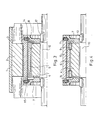
- a housing 1 or a holding plate is provided for fixing a stator 2 provided with stator windings 3.
- a rotor is installed coaxially to the stator 2, which rotor is provided with rotor windings 5 (FIGS. 1 and 5) or with a cage 15 (FIGS. 2 to 4) in a conventional manner.
- the rotor windings 5 or the cage 15 form the rotor together with a magnetically excited body 4 of known construction (e.g. laminated core), an air gap 13 being provided between the stator 2 and the rotor.
- the conventional motor structure is modified according to the invention in such a way that an additional rotary element 6 is provided between the stator 2 and the magnetically excited body 4, which can rotate freely with respect to the rotor which is firmly supported on the motor shaft 10.
- the rotor therefore consists of the body 4 and the rotor windings 5 or the cage 15, and is adapted to the rotary element 6, which is freely supported on the motor shaft 10 directly or on the body 4.
- the rotating element 6 is made of a permanent magnetic material and can wal be zen-shaped or annular.
- the rotary element 6 is supported concentrically to the rotor via bearings, in particular needle bearings 8, on the motor shaft 10 or the first part 4, in particular the rotor winding 5.
- a disk 7 serves to support the roller-shaped rotating element 6, and that is supported on the nail bearings 8.
- the latter are adapted snap rings 9, one or more clamping screws 11 being provided for fastening the rotary element 6 to the disk 7.
- slide bearings 18 FIG. 3
- the disc 7 is made of a light material, such as plastic or aluminum; it does not have to be made of a ferromagnetic material.
- the rotor of the induction motor is equipped with a cage 15 (FIGS. 2, 3 and 4), a short-circuit ring 16 being provided which is firmly connected to the body 4.
- the short-circuit ring 16 serves to support the nail bearings 8 and offers the possibility of simple installation of the rotary element 6.
- the use of a split rotor creates two air gaps in the interior of the induction motor.
- the rotating element 6 occupies part of the air gap 13 between the stator 2 and the rotor.
- the enlargement of the air gap 13 increases the magnetizing current of the induction motor, but this can be compensated for by the appropriate selection of the permanent magnetic material of the rotating element 6.
- an inner air gap 14 can be formed in the rotor, which is in or under the cage 15, but always above the body 4.
- the inner air gap 14 - which is not absolutely necessary - receives the rotary element 6, which is arranged in the all-round closed inner air gap 14 and is secured at a higher level against interference windings.
- the cage 15 is made of aluminum or other non-feromagnetic metal (FIG. 3 or 4) and in this embodiment is firmly connected to the respective disk 7 via the clamping screws 11.
- the discs 7 are firmly connected to the motor shaft 10 via tongue springs 12.
- the plain bearings 18 shown in FIG. 3 can be replaced by the nail bearings 8 according to FIG.
- the stator 2 has no slot and the stator winding 3 is embedded in synthetic resin; it forms an air gap winding.
- the rotating element 6 is constructed in the form of a flat disk arranged axially between the shaft-fixed body 4 of the rotor and the stator 2.
- the straight planes of rotation of the rotor and the rotating element 6 are parallel in this solution.
- the rotating element 6 can be supported both on the stator 2 (e.g. on a circular disc-shaped projection thereon), on the motor shaft 10 and - as can be seen in FIG. 5 - on the rotor in a free-running manner via the bearing 8.
- the bearings are loaded in accordance with the difference between the speed of the asynchronous motor and that of the synchronous motor. Therefore, the life of the bearings is long.
- the energy requirement is low because of the use of the rotating element 6 as a synchronous rotor part of the induction motor, which leads to a very small value of the load angle, regardless of whether the rotating element 6 is installed inside or outside the rotor.
- the rotating element 6 can be roller-shaped (FIGS. 1 to 4), disk-shaped (FIG. 5) or circular.
- the ring-shaped configuration is similar to the roller-shaped or disc-shaped - depending on the arrangement of the magnetic material of the rotating element shown below.
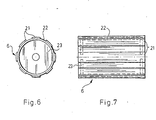
- the rotating element 6 has a cylindrical shape, it serves as an envelope surrounding the rotor, which is closed on both sides with end walls 23 made of a light material such as plastic or aluminum.
- the end walls 23 are adapted to the bearings 8 or 18 (not shown in FIGS. 6 and 7) and are connected to a holding cylinder 22 suitably prepared as a hollow body made of aluminum or plastic.
- ferromagnetic tapes 21 are glued, which have been produced, for example, by powder metallurgical methods.
- the tapes 21 are advantageously pre-magnetized in the radial direction in a known manner so that the number of poles of the magnetic field is equal to the number of poles of the stator winding 3. If necessary, 21 air gaps can be prepared in the holding cylinder 22 between the bands.
- the holding cylinder 22 can independently form the rotary element 6 if it consists of a ferromagnetic material, the end walls 23 being formed, for example, from plastic.
- the rotating element 6 is a disk, as can be seen from FIG. 5, the strips 21 are glued on perpendicular to the motor shaft 10 and premagnetized in the axial direction.
- the disc can be made of non-ferromagnetic material (with glued ferromagnetic tapes) as well as a ferromagnetic material (without tapes).
- the roller-shaped rotating element 6 and also the disk-shaped or ring-shaped rotating element can be supported both on the motor shaft 10 and in the stator 2 or in the rotor, the adaptation, the installation, expediently depending on the motor design, being able to be determined.
- the rotary element 6 causes an increase in the air gap between the stator 2 and the rotor, which in itself results in a slight deterioration in the working parameters (the would increase the magnetizing current).
- This effect follows the fact that, due to its thickness, the rotating element requires an increase in the distance between the stator and the rotor.
- the thickness of the rotating element is generally about 3 ... 3.5 mm; it can be larger for higher engine outputs.
- the presence of the ferromagnetic rotary element 6 is associated with such advantages that the mentioned deterioration is completely compensated for, since the modern ferromagnetic materials can ensure a really high coercive force.
- the advantages of the synchronous motors and the induction motors are combined in such a way that the rotary element 6, as a supplementary rotor, provides magnetic energy, whereby the magnetization of the motor is facilitated and less power from the network is required to build up the main magnetic field (rotating field).
- the supply voltage is switched on (which is single-phase or three-phase)
- a circularly symmetrical or elliptical magnetic field is created in the stator winding, which rotates at synchronous speed.
- the rotor and the rotating element 6 are accelerated to the asynchronous speed, upon reaching which the rotating element 6 is further accelerated to the synchronous speed in a very fast-running process.
- the rotating element 6 causes excitation which is added to that of the main magnetic field of the motor.
- the magnetic excitation between the stand and the rotor can be significantly increased with the appropriate selection of the materials.
- the acceleration of the rotating element can be improved by the presence of a magnetically non-excitable metal in the ferromagnetic material as the holding cylinder 22, which ensures a cage effect.
- the power factor can be set according to the requirements. At loads lower than those following the power factor, the induction motor works capacitively as an overexcited synchronous motor, and when the load exceeds that corresponding to the selected operating point, the reactive current requirement is significantly lower than with the known induction motors.
- the rotary element according to the invention can be used in all induction motors.
- the motor power, the number of winding poles, the number of phases of the supply voltage, the arrangement of the rotor are practically not limited;
- the supplementary rotor can be used in the motor without further ado and then a significant improvement in the energetic properties (with a power factor of up to 0.95, i.e. with reduced consumption of reactive power) can be expected.
Landscapes
- Engineering & Computer Science (AREA)
- Power Engineering (AREA)
- Permanent Magnet Type Synchronous Machine (AREA)
- Iron Core Of Rotating Electric Machines (AREA)
- Permanent Field Magnets Of Synchronous Machinery (AREA)
- Induction Machinery (AREA)
Abstract
Induktionsmotor, der einen Ständer (2) mit einer Ständerwicklung sowie einen davon über einen Luftspalt (13) getrennten, mit einer Motorwelle (10) verbundenen Läufer enthält, wobei der Läufer mit einem stromleitenden Element (5, 15) sowie einem magnetisch erregten Körper (4) versehen ist, wobei im Luftspalt (13) ein zwischen dem Ständer und dem magnetisch erregten Körper (4) angeordnetes, gegen den Läufer freilaufend abgestütztes, aus permanentmagnetischem Stoff ausgebildetes Drehelement (6) vorgesehen ist. 
Description
Die Erfindung betrifft einen Induktionsmotor, der einen Ständer mit einer Ständerwicklung sowie einen mit einer Motorwelle verbundenen und über einen Luftspalt vom Ständer getrennten Läufer enthält. Beim erfindungsgemäßen Induktionsmotor kann der Leistungsfaktor in einem breiten Einstellungsbereich beliebig ausgewählt werden.The invention relates to an induction motor which contains a stator with a stator winding and a rotor connected to a motor shaft and separated from the stator via an air gap. In the induction motor according to the invention, the power factor can be selected as desired in a wide setting range.
Die Induktionsmotoren sind solche elektrischen Maschinen, bei denen ein Ständer mit einer Ständerwicklung sowie ein Läufer vorgesehen sind, der eine Wicklung aufweist, in welcher über die Ständerwicklung der Läuferstrom induziert wird. Die Induktionsmotoren können im einfachsten Aufbau mit einem Käfigläufer (Kurzschlußläufer) ausgestattet sein, wobei der Käfig aus Stäben und mit den Stäben auf der Stirnseite des Läufers verbundenen Ringen (Kurzschlußringen) besteht.The induction motors are electrical machines in which a stator with a stator winding and a rotor are provided which has a winding in which the rotor current is induced via the stator winding. The simplest design of the induction motors can be equipped with a squirrel-cage rotor (short-circuit rotor), the cage consisting of rods and rings (short-circuit rings) connected to the rods on the end face of the rotor.
Der Wirkungsgrad der elektrischen Motoren kann durch das Verhältnis der an der Welle abnehmbaren wirksamen Leistung zu der dem Netz entnommenen Leistung definiert werden. Bei den Induktionsmotoren hängt die letztere von der Spannung, dem Strom und dem Phasenwinkel ab. Die an der Welle abnehmbare wirksame Leistung ist von vielen verschiedenen Faktoren abhängig. Es ist klar, daß der Wirkungsgrad durch die Verminderung der dem Netz entnommenen Leistung bei einem unveränderten oder begrenzt veränderten Wert der wirksamen Leistung verbessert werden kann.The efficiency of the electric motors can be defined by the ratio of the effective power that can be taken off the shaft to the power drawn from the network. In the case of induction motors, the latter depends on the voltage, the current and the phase angle. The effective power that can be removed from the shaft depends on many different factors. It is clear that the efficiency can be improved by reducing the power drawn from the network with the value of the effective power unchanged or changed to a limited extent.
Einen großen Teil der aufgenommenen Leistung bildet die Blindleistung, die durch aufwendige Kondensatoranordnungen stets begrenzt werden kann. Die Verwendung der den Blindstrom kompensierenden Kondensatoren bedeutet jedoch immer eine Verschlechterung der Arbeitsbedingungen und eine Erhöhung der Herstellungskosten der Induktionsmotoren. Die Blindleistung ist von der Speisespannung und dem Speisestrom sowie dem Leistungsfaktor abhängig, wobei der Leistungsfaktor den Cosinus des zwischen dem Strom und der Spannung bestehenden Phasenwinkelunterschieds bedeutet.A large part of the power consumed is reactive power, which can always be limited by complex capacitor arrangements. However, the use of the capacitors compensating for the reactive current always means a deterioration in the working conditions and one Increase the manufacturing cost of induction motors. The reactive power depends on the supply voltage and the supply current as well as the power factor, the power factor being the cosine of the phase angle difference between the current and the voltage.
Die Verbesserung des Leistungsfaktors wurde bei vielen Erfindungen als Ziel gesetzt. Neben der Verwendung der Kondensatoranlagen sind verschiedene Lösungen bekannt, wie unter anderen beim Hysteresemotor nach der DE-C-32 32 914. Dort wird ein als Hohlzylinder ausgebildeter dauermagnetischer Läufer vorgeschlagen, der während des Betriebes des Motors einer radialen Magnetisierung unterzogen wird. Durch die zweckmäßige Auswahl der Dicke der Wände kann erreicht werden, daß die Magnetkreise fast alle durch den Luftspalt des Motors geschlossen werden; daher ist eine Verbesserung sowohl des Wirkungsgrades als auch des Leistungsfaktors erreichbar.Improving the power factor has been the goal of many inventions. In addition to the use of the capacitor systems, various solutions are known, such as the hysteresis motor according to DE-C-32 32 914. A permanent magnet rotor designed as a hollow cylinder is proposed there, which is subjected to radial magnetization during operation of the motor. By appropriately selecting the thickness of the walls it can be achieved that the magnetic circuits are almost all closed by the air gap of the motor; therefore an improvement in both the efficiency and the power factor can be achieved.
Der Nachteil der bekannten Lösung besteht darin, daß die Verbesserung des Leistungsfaktors schlecht einstellbar ist, d.h. bei verschiedenen Motoren gleichen Aufbaus können unterschiedliche Leistungsfaktoren auftreten.The disadvantage of the known solution is that the improvement in the power factor is difficult to adjust, i.e. different power factors can occur with different motors of the same construction.
Der gleiche Nachteil kann im Zusammenhang mit dem in der DE-C-28 32 165 dargestellten Reluktanzgenerator erwähnt werden. In dieser Patentschrift wurde die Verwendung einer aus dauermagnetischem Stoff hergestellten Generatorwelle vorgeschlagen. Der Läufer des Generators ist mit dieser Welle verbunden, welche auch ein den Magnetfluß ablenkendes Element trägt. Der Magnetfluß der Erregerwicklung wird im Mittelteil des Generators konzentriert, wobei der niedrigste magnetische Widerstand zu überwinden ist, da das aus einem ferromagnetischen Stoff bestehende flußablenkende Element den Mittelbereich der Erregerwicklung und die Welle ausfüllt.The same disadvantage can be mentioned in connection with the reluctance generator shown in DE-C-28 32 165. In this patent, the use of a generator shaft made of permanent magnetic material was proposed. The rotor of the generator is connected to this shaft, which also carries an element that deflects the magnetic flux. The magnetic flux of the excitation winding is concentrated in the middle part of the generator, the lowest magnetic resistance having to be overcome, since the flux-deflecting element made of a ferromagnetic material fills the central region of the excitation winding and the shaft.
Durch die Erfindung wird die Aufgabe gelöst, den Wirkungsgrad der Induktionsmotoren mit einfachen Mitteln zu verbessern, d.h. einen Induktionsmotor zu schaffen, dessen Leistungsfaktor auf einen beliebig ausgewählten Arbeitspunkt mit vorbestimmtem Wert bei hoher Genauigkeit ausgelegt werden kann.The object of the invention is to improve the efficiency of the induction motors with simple means, ie to create an induction motor, the power factor of which is designed for an arbitrarily selected operating point with a predetermined value and with high accuracy can be.
Die Erfindung beruht auf der Erkenntnis, daß die Erhöhung und Einstellbarkeit des Leistungsfaktors durch Verwendung eines ergänzenden Rotors beim Läufer erreichbar ist, falls jener aus ferromagnetischem Stoff besteht und gegenüber dem Läufer freilaufend abgestützt ist.The invention is based on the knowledge that the increase and adjustability of the power factor can be achieved by using a supplementary rotor in the rotor if the rotor is made of ferromagnetic material and is supported in a free-running manner with respect to the rotor.
In der Patentliteratur sind Vorschläge zu finden, wonach im Innenraum eines Ständers eines Motors mehrere drehbare Elemente angeordnet sind. Jedoch können dadurch, wie dem Unteren entnehmbar ist, lediglich Spezialaufgaben bei speziellen Motoren gelöst werden.The patent literature suggests that several rotatable elements are arranged in the interior of a stator of a motor. However, as can be seen from the lower one, only special tasks can be solved for special motors.
Der Einbau eines ergänzenden Läufers ist z.B. aus der DE-A-30 45 820 erkennbar. Diesem Vorschlag nach werden auf der Motorwelle ein Käfigläufer und ein mit Wicklung versehener Innenläufer zueinander konzentrisch eingebaut, wobei der Außenläufer und der Ständer mit einer äußeren Spannungsquelle verbunden sind. Dadurch können unterschiedliche Drehzahlen der Läufer erreicht werden. Der derart ausgebildete Motor ist eine Spezialmaschine, bei der die Erhöhung des Leistungsfaktors nicht möglich ist.The installation of a supplementary runner is e.g. can be seen from DE-A-30 45 820. According to this proposal, a squirrel-cage rotor and an inner rotor provided with a winding are installed concentrically with one another on the motor shaft, the outer rotor and the stator being connected to an external voltage source. Different speeds of the rotors can be achieved in this way. The engine designed in this way is a special machine in which it is not possible to increase the power factor.
In der WO-85/03174 wurde die Unterteilung des Läufers auf zwei Teile vorgeschlagen, und zwar auf den äußeren Käfig sowie einen hiergegen freilaufenden inneren ferromagnetischen Teil. Derart entsteht ein einphasiger Motor kleiner Leistung mit zwei oder vier Polen, wobei die Erhöhung des Leistungsfaktors als Aufgabe nicht auftritt und praktisch nicht erreichbar ist.In WO-85/03174 it was proposed to divide the rotor into two parts, namely the outer cage and an inner ferromagnetic part running freely against it. This creates a single-phase motor of low power with two or four poles, whereby the increase in the power factor does not occur as a task and is practically impossible to achieve.
Zur Lösung der gestellten Aufgabe wurde ein Induktionsmotor geschaffen, der einen Ständer mit einer Ständerwicklung sowie einen davon über einen Luftspalt getrennten, mit einer Motorwelle verbundenen Läufer enthält, wobei der Läufer mit einem stromleitenden Element sowie einem magnetisch erregten Körper ausgestaltet ist und erfindungsgemäß im Luftspalt ein zwischen dem Ständer und dem Läufer angeordnetes, gegen den Läufer freilaufend unterstütztes, aus permanentmagnetischem (vormagnetisierten ferromagnetischen) Stoff vorbereitetes Drehelement vorgesehen ist, das zum Läufer koaxial entweder oberhalb des stromleitenden Elementes (des Käfigs oder der Wicklung) des Läufers oder in einem Luftspalt zwischen dem stromleitenden Element und dem magnetisch erregten Körper des Läufers angeordnet ist.To solve the problem, an induction motor was created which contains a stator with a stator winding and a rotor separated from it via an air gap and connected to a motor shaft, the rotor being designed with a current-conducting element and a magnetically excited body and according to the invention in the air gap between the stator and the rotor arranged, freely supported against the rotor, prepared from permanent magnetic (pre-magnetized ferromagnetic) material is provided rotating element The rotor is arranged coaxially either above the current-conducting element (the cage or the winding) of the rotor or in an air gap between the current-conducting element and the magnetically excited body of the rotor.
Wie bekannt, kann der Induktionsmotor mit einem Innenläufer, einem Mittelläufer oder einem Außenläufer aufgebaut werden. Dementsprechend kann das Drehelement auf dem Läufer entweder auf dessen äußeren Oberfläche oder auf dem Körper, weiter auf der Motorwelle und bei Verwendung eines Außenläufers auf dem Ständer gelagert sein.As is known, the induction motor can be constructed with an inner rotor, a middle rotor or an outer rotor. Accordingly, the rotating element can be mounted on the rotor either on its outer surface or on the body, further on the motor shaft and, if an external rotor is used, on the stator.
Das Drehelement ist vorteilhaft zumindest so lang wie der unter ihm liegende Teil des Läufers. Es ist zweckmäßig, das Drehelement als walzenförmige Hülse auszubilden, die zum Beispiel aus dünnen ferromagnetischen Bändern besteht und - dank der Vormagnetisierung - die gleiche Anzahl von Polen aufweist wie die Ständerwicklung. Die in radialer Richtung vormagnetisierten ferromagnetischen Bänder können auf der inneren oder äußeren Oberfläche einer magnetisch nicht erregbaren metallischen, z.B. aus Aluminium vorbereiteten Walze aufgeklebt werden. Der Grundstoff der Bänder kann unter anderen Eisen oder ein Seltenmetallmagnet (zum Beispiel Samarium-Kobalt oder auf Neodimium basierender Stoff) sein.The rotating element is advantageously at least as long as the part of the rotor lying below it. It is expedient to design the rotary element as a roller-shaped sleeve which, for example, consists of thin ferromagnetic strips and, thanks to the premagnetization, has the same number of poles as the stator winding. The ferromagnetic tapes premagnetized in the radial direction may be on the inner or outer surface of a magnetically non-excitable metallic, e.g. prepared from aluminum prepared roller. The base material of the bands can be iron or a rare metal magnet (for example samarium-cobalt or neodimium-based material).
Das auf dem Ständer abgestützte Drehelement ist vorteilhaft als Kreisring ausgebildet, der gleichfalls mit in radialer Richtung vormagnetisiertem ferromagnetischen Stoff besteht. Beim Mittelläufer bildet das Drehelement eine Scheibe, die auf der Motorwelle gelagert ist, wobei der ferromagnetische Stoff der Scheibe in axialer Richtung vormagnetisiert ist.The rotating element supported on the stand is advantageously designed as a circular ring which also consists of ferromagnetic material which is premagnetized in the radial direction. In the middle rotor, the rotating element forms a disk which is mounted on the motor shaft, the ferromagnetic material of the disk being premagnetized in the axial direction.
Bei dem erfindungsgemäßen Induktionsmotor, falls jener einen mit einem Käfig versehenen Kurzschlußläufer enthält, ist es vorteilhaft, das Drehelement auf einem Kurzschlußring abzustützen, wobei der Kurzschlußring mit dem stromleitenden Element fest verbunden ist. Die Abstützung erfolgt im allgemeinen über Nadellager oder Gleitlager.In the case of the induction motor according to the invention, if it contains a short-circuit rotor provided with a cage, it is advantageous to support the rotary element on a short-circuit ring, the short-circuit ring being firmly connected to the current-carrying element. The support is generally via needle bearings or plain bearings.
Bei einem erfindungsgemäßen Asynchron-Induktionsmotor wird daher erfin dungsgemäß ein ergänzender Synchronläufer vorgesehen, der entweder unmittelbar auf der Motorwelle oder auf dem Läufer beweglich abgestützt einen synchron zu dem magnetischen Drehfeld des Motors freilaufenden Teil bildet und zur Erregung des Läufers des Induktionsmotors beitragen kann.An asynchronous induction motor according to the invention is therefore invented According to the invention, a supplementary synchronous rotor is provided which, either directly supported on the motor shaft or movably supported on the rotor, forms a part which runs freely in synchronism with the magnetic rotating field of the motor and can contribute to excitation of the rotor of the induction motor.
Dadurch können die Kupfermenge des Motors und die zur Erregung notwendige Leistung vermindert werden und wird die dem Netz entnommene Blindleistung verringert. Derart vermindert sich die Energieaufnahme aus dem elektrischen Netz. Ein weiterer Vorteil besteht darin, daß der Leistungsfaktor mit gewünschtem Wert einem vorgewählten Arbeitspunkt zugeordnet werden kann.As a result, the amount of copper in the motor and the power required for excitation can be reduced and the reactive power drawn from the network is reduced. This reduces the energy consumption from the electrical network. Another advantage is that the power factor can be assigned to a preselected operating point with the desired value.
Durch die erfindungsgemäße Lösung kann die Aufnahme der wirksamen Leistung vom Netz im Verhältnis zur Aufnahme der Blindleistung bei den Endpunkten des Netzes vereinfacht werden; so wird die Blindleistungsaufnahme des durch das Netz gespeisten Systems vermindert. Die Erfindung kann sowohl bei einphasigen als auch dreiphasigen Induktionsmotoren beliebiger Leistung (zum Beispiel von 40 W bis 1000 kW), und insbesondere bei den in Haushalten eingesetzten Motoren verwendet werden.The solution according to the invention can simplify the absorption of the effective power from the network in relation to the absorption of the reactive power at the end points of the network; this reduces the reactive power consumption of the system fed by the network. The invention can be used both for single-phase and three-phase induction motors of any power (for example from 40 W to 1000 kW), and in particular for the motors used in households.
Die Erfindung wird im folgenden anhand von bevorzugten Ausführungsformen näher erläutert, die aus der Zeichnung ersichtlich sind. In der Zeichnung zeigen:
Figur 1 den Querschnitt eines erfindungsgemäßen Induktionsmotors mit einem Läufer und einem ergänzenden Rotor im Luftspalt des Motors,Figur 2 den Querschnitt eines erfindungsgemäßen Induktionsmotors mit einem Läufer, auf dem ein freilaufendes Teil als ein ergänzender Rotor gelagert ist, ohne Darstellung des Ständers,Figur 3 den Querschnitt eines erfindungsgemäßen Induktionsmotors mit einem inneren Läufer und einem inneren Luftspalt, worin ein ergänzender Rotor angeordnet ist,Figur 4 den Querschnitt eines erfindungsgemäßen Läufers des in Fig. 3 dargestellten Induktionsmotors mit einem inneren Läufer und einem inneren Luftspalt, worin ein ergänzender Rotor vorgesehen ist, ohne Darstellung des Ständers,Figur 5 den Längsschnitt eines mit Zwischenläufer und parallel dazu angeordnetem ergänzenden Rotor ausgebildeten erfindungsgemäßen Induktionsmotors,Figur 6 die Vorderansicht eines als Walze ausgebildeten Drehelementes, undFigur 7 die Seitenansicht des Drehelementes gemäß Fig. 6
- 1 shows the cross section of an induction motor according to the invention with a rotor and a supplementary rotor in the air gap of the motor,
- FIG. 2 shows the cross section of an induction motor according to the invention with a rotor on which a free-running part is mounted as a supplementary rotor, without showing the stator,
- 3 shows the cross section of an induction motor according to the invention with an inner rotor and an inner air gap, in which an additional rotor is arranged,
- FIG. 4 shows the cross section of a rotor according to the invention of the induction motor shown in FIG. 3 with an inner rotor and an inner air gap, in which an additional rotor is provided, without showing the stator,
- 5 shows the longitudinal section of an induction motor according to the invention formed with an intermediate rotor and a complementary rotor arranged parallel thereto, FIG.
- 6 shows the front view of a rotary element designed as a roller, and
- FIG. 7 shows the side view of the rotary element according to FIG. 6
Zur näheren Erläuterung werden einige Ausführungsbeispiele mit Induktionsmotoren ausgewählt, bei denen der Läufer im Innenraum des Ständers angeordnet ist (Fig. 1 bis 4). Jedoch kann das Grundprinzip der Erfindung auch bei solchen Induktionsmotoren verwirklicht werden, bei denen der Läufer außerhalb des Ständers angeordnet ist (Fig. 5).For a more detailed explanation, some exemplary embodiments with induction motors are selected in which the rotor is arranged in the interior of the stator (FIGS. 1 to 4). However, the basic principle of the invention can also be implemented in those induction motors in which the rotor is arranged outside the stator (FIG. 5).
In einem Induktionsmotor mit Innen- und Außenläufer im Allgemeinen und bei dem erfindungsgemäßen Induktionsmotor im Besonderen ist ein Gehäuse 1 oder ein Halteplatte zur Festlegung eines mit Ständerwicklungen 3 versehenen Ständers 2 vorgesehen. Mit einer Motorwelle 10 fest verbunden ist koaxial zum Ständer 2 ein Läufer eingebaut, welcher mit Läuferwicklungen 5 (Fig. 1 und 5) oder mit einem Käfig 15 (Fig. 2 bis 4) in herkömmlicher Weise versehen ist. Die Läuferwicklungen 5 bzw. der Käfig 15 bilden den Läufer gemeinsam mit einem magnetisch erregten Körper 4 bekannten Aufbaus (z.B. Blechpaket), wobei zwischen dem Ständer 2 und dem Läufer ein Luftspalt 13 vorgesehen ist.In an induction motor with internal and external rotor in general and in the induction motor according to the invention in particular, a
Der herkömmliche Motoraufbau wird erfindungsgemäß so verändert, daß zwischen dem Ständer 2 und dem magnetisch erregten Körper 4 ein zusätzliches Drehelement 6 vorgesehen ist, welches gegenüber dem auf der Motorwelle 10 fest abgestützten Läufer freilaufend drehbar ist. Der Läufer besteht daher aus dem Körper 4 und den Läuferwicklungen 5 oder dem Käfig 15, und ist an das Drehelement 6 angepaßt, das freilaufend auf der Motorwelle 10 unmittelbar oder auf dem Körper 4 gelagert ist. Das Drehelement 6 ist aus einem dauermagnetischen Stoff aufgebaut und kann wal zenförmig oder ringförmig ausgebildet sein. Das Drehelement 6 wird über Lager, insbesondere Nadellager 8, auf der Motorwelle 10 oder dem ersten Teil 4, insbesondere der Läuferwicklung 5 konzentrisch zum Läufer abgestützt.The conventional motor structure is modified according to the invention in such a way that an additional
Wie aus Figur 1 ersichtlich, dient eine Scheibe 7 zur Abstützung des walzenförmigen Drehelementes 6, und jene ist auf den Nagellagern 8 abgestützt. Die letzteren sind Sprengringen 9 angepaßt, wobei eine oder mehrere Spannschrauben 11 zur Befestigung des Drehelementes 6 an der Scheibe 7 vorgesehen sind. Offensichtlich können andere Befestigungsmöglichkeiten verwendet werden und ist auch die Verwendung von Gleitlagern 18 (Fig. 3) als vorteilhaft anzusehen. Die Scheibe 7 besteht aus einem leichten Material, wie Kunststoff oder Aluminium; sie muß nicht aus einem ferromagnetischen Stoff ausgebildet werden.As can be seen from FIG. 1, a
Bei einigen Typen ist der Läufer des Induktionsmotors mit einem Käfig 15 ausgestattet (Figuren 2, 3 und 4), wobei ein Kurzschlußring 16 vorgesehen ist, der mit dem Körper 4 fest verbunden ist. Der Kurzschlußring 16 dient zur Abstützung der Nagellager 8 und bietet die Möglichkeit des einfachen Einbaus des Drehelementes 6.In some types, the rotor of the induction motor is equipped with a cage 15 (FIGS. 2, 3 and 4), a short-
Wie es der Figur 1 zu entnehmen ist, entstehen durch die Verwendung eines geteilten Läufers zwei Luftspalte im Innenraum des Induktionsmotors. Das Drehelement 6 besetzt einen Teil des Luftspaltes 13 zwischen dem Ständer 2 und dem Läufer. Zwar vergrößert sich durch die Vergrößerung des Luftspaltes 13 der Magnetisierungsstrom des Induktionsmotors, was jedoch durch die zweckmäßige Auswahl des dauermagnetischen Stoffes des Drehelementes 6 gut kompensiert werden kann.As can be seen in FIG. 1, the use of a split rotor creates two air gaps in the interior of the induction motor. The
Wie es der Figur 3 entnehmbar ist, kann ein innerer Luftspalt 14 im Läufer ausgebildet sein, der in oder unter dem Käfig 15, jedoch immer oberhalb des Körpers 4 liegt. Der innere Luftspalt 14 - der nicht unbedingt notwendig ist - nimmt das Drehelement 6 auf, welches in dem allseitig geschlossenen inneren Luftspalt 14 angeordnet auf erhöhtem Pegel gegen Störwicklungen gesichert ist.As can be seen in FIG. 3, an
Der Käfig 15 besteht - wie herkömmlich - aus Aluminium oder anderem nicht feromagnetischen Metall (Figur 3 oder 4) und ist bei dieser Ausführungsform über die Spannschrauben 11 mit der jeweilgen Scheibe 7 fest verbunden. Die Scheiben 7 sind über Nutfedern 12 mit der Motorwelle 10 fest verbunden. Die aus Figur 3 ersichtlichen Gleitlager 18 können durch die Nagellager 8 nach Figur 4 ersetzt werden.As is conventional, the
Im erfindungsgemäßen Induktionsmotor mit Zwischenläufer nach Figur 5 weist der Ständer 2 keine Nut auf und die Ständerwicklung 3 ist in Kunstharz eingebettet; sie bildet eine Luftspaltwicklung.In the induction motor according to the invention with intermediate rotor according to FIG. 5, the
Das Drehelement 6 ist in Form einer flachen, axial zwischen dem wellenfesten Körper 4 des Läufers und dem Ständer 2 angeordneten Scheibe aufgebaut. Die geraden Drehungsebenen des Läufers und des Drehelementes 6 liegen bei dieser Lösung parallel. Das Drehelement 6 kann sowohl an dem Ständer 2 (z.B. auf einem daran ausgebildeten kreisscheibenförmigen Vorsprung), an der Motorwelle 10 als auch - wie in Figur 5 ersichtlich ist - am Läufer freilaufend über das Lager 8 abgestützt sein.The
Im Betrieb des erfindungsgemäßen Induktionsmotors sind die Lager (Nagellager 8 oder Gleitlager 18) entsprechend des Unterschieds zwischen der Drehzahl des Asynchronmotors und derjenigen des Synchronmotors belastet. Daher ist die Lebensdauer der Lager hoch. Der Energiebedarf ist wegen der Verwendung des Drehelementes 6 als Synchron-Läuferteil des Induktionsmotors gering, die zu einem sehr kleinen Wert des Belastungswinkels führt, unabhängig davon, ob das Drehelement 6 innerhalb oder außerhalb des Läufers eingebaut ist.During operation of the induction motor according to the invention, the bearings (nail
Das Drehelement 6 kann wie erwähnt walzenförmig (Figuren 1 bis 4), scheibenförmig (Figur 5) oder kreisringförmig sein. Die ringförmige Ausbildung ist zur walzenförmigen oder zur scheibenförmigen ähnlich - abhängig von der nachstehend dargestellten Anordnung des magnetischen Stoffes des Drehelementes.As mentioned, the
Das Drehelement 6 nach den Figuren 6 und 7 ist walzenförmig ausgebildet, es dient als eine den Läufer umgebende Hülle, die mit aus einem leichten Material, wie Kunststoff oder Aluminium ausgebildeten Abschlußwänden 23 beidseitig geschlossen ist. Die Abschlußwände 23 sind an die Lager 8 oder 18 angepaßt (in den Figuren 6 und 7 nicht gezeigt) und mit einem zweckmäßig als Hohlkörper aus Aluminium oder Kunststoff vorbereiteten Haltezylinder 22 verbunden. Auf der (inneren oder äußeren) Oberfläche des Haltezylinders 22 sind ferromagnetische Bänder 21 aufgeklebt, die z.B. durch pulvermetallurgische Methoden hergestellt worden sind. Die Bänder 21 sind in bekannter Weise in radialer Richtung vorteilhaft so vormagnetisiert, daß die Anzahl der Pole des Magnetfeldes zu der Polanzahl der Ständerwicklung 3 gleich ist. Wenn notwendig können im Haltezylinder 22 zwischen den Bändern 21 Luftspalte vorbereitet werden. Der Haltezylinder 22 kann selbstständig das Drehelement 6 bilden, falls jener aus einem ferromagnetischen Stoff besteht, wobei die Abschlußwände 23 z.B. aus Kunststoff ausgebildet sind.The
Bei kostspieligen, auf Seltenerdmetallen (z.B. Kobalt-Samarium-Mischung, Neodium) basierenden Bändern 21 können jene aus hintereinander und nebeneinander in Reihen angeordneten Teilen mit Abmessungen von 1,8 x 4, 5 x 24 mm vorbereitet werden, wobei ein aus Aluminium bestehender Haltezylinder 22 mit einer Wanddicke von z.B. 1,5 mm vorgesehen ist.In the case of
Ist das Drehelement 6 eine Scheibe, wie aus Figur 5 ersichtlich ist, so sind die Bänder 21 senkrecht zur Motorwelle 10 aufgeklebt und in axialer Richtung vormagnetisiert. Die Scheibe kann sowohl aus nichtferromagnetischem Stoff (mit aufgeklebten ferromagnetischen Bändern), als auch einem ferromagnetischen Stoff (ohne Bänder) ausgebildet werden. Das walzenförmige Drehelement 6 und ebenso das scheibenförmige oder ringförmige Drehelement kann sowohl an der Motorwelle 10 als auch im Ständer 2 oder im Läufer abgestützt werden, wobei die Anpassung, der Einbau, zweckmäßig von der Motorkonstruktion abhängig, bestimmt werden kann.If the
Den obigen Ausführungen ist zu entnehmen, daß das Drehelement 6 eine Vergrößerung des Luftspaltes zwischen dem Ständer 2 und dem Läufer bewirkt, was an sich eine geringe Verschlechterung der Arbeitsparameter (die Erhöhung des Magnetisierungsstromes) hervorrufen würde. Dieser Effekt folgt der Tatsache, daß das Drehelement aufgrund seiner Dicke einer Vergrößerung des Abstandes zwischen dem Ständer und dem Läufer bedarf. Die Dicke des Drehelementes macht im Allgemeinen etwa 3 ... 3,5 mm aus; bei höheren Motorleistungen kann sie größer sein. Jedoch ist die Anwesenheit des ferromagnetischen Drehelementes 6 mit solchen Vorteilen verbunden, daß die erwähnte Verschlechterung vollständig kompensiert wird, da die modernen ferromagnetischen Stoffe eine wirklich hohe Koerzitivkraft gewährleisten können.It can be seen from the above statements that the
Im erfindungsgemäßen Induktionsmotor werden die Vorteile der Synchronmotoren und der Induktionsmotoren derart vereinigt, daß das Drehelement 6 als ein ergänzender Rotor magnetische Energie leistet, wodurch die Magnetisierung des Motors erleichtert wird und weniger Leistung aus dem Netz zum Aufbau des magnetischen Hauptfeldes (Drehfeldes) benötigt wird. Beim Einschalten der Speisespannung (die einphasig oder dreiphasig ist) entsteht in der Ständerwicklung ein kreissymmetrisches oder elliptisches Magnetfeld, das sich mit Synchrondrehzahl dreht. Dabei werden der Läufer und das Drehelement 6 zur Asynchrondrehzahl beschleunigt, bei deren Erreichen das Drehelement 6 auf die Synchrondrehzahl in einem sehr schnell ablaufenden Prozeß weiter beschleunigt wird. In diesem Zustande bewirkt das Drehelement 6 eine Erregung, welche zu der des magnetischen Hauptfeldes des Motors hinzugefügt wird. Derart kann mit entspechender Auswahl der Stoffe die magnetische Erregung zwischen dem Ständer und dem Läufer bedeutend erhöht werden. Die Beschleunigung des Drehelementes kann durch die Anwesenheit eines magnetisch nicht erregbaren Metalls beim ferromagnetischen Stoff als Haltezylinder 22 verbessert werden, womit eine Käfigwirkung gewährleistet wird.In the induction motor according to the invention, the advantages of the synchronous motors and the induction motors are combined in such a way that the
Durch zweckmäßige Auswahl des dauermagnetischen Stoffes kann der Leistungsfaktor gemäß den Anforderungen eingestellt werden. Bei den Belastungen, die niedriger sind als die dem Leistungsfaktor folgenden, arbeitet der Induktionsmotor auf kapazitive Weise als ein überregter Synchronmotor, und wenn die Belastung die dem ausgewählten Arbeitspunkt entsprechende überschreitet, ist der Blindstrombedarf bedeutend geringer als bei den bekannten Induktionsmotoren.By appropriately selecting the permanent magnetic material, the power factor can be set according to the requirements. At loads lower than those following the power factor, the induction motor works capacitively as an overexcited synchronous motor, and when the load exceeds that corresponding to the selected operating point, the reactive current requirement is significantly lower than with the known induction motors.
Das erfindungsgemäße Drehelement kann bei allen Induktionsmotoren verwendet werden. Die Motorleistung, die Anzahl der Wicklungspole, die Anzahl der Phasen der Speisespannung, die Anordnung des Läufers sind praktisch nicht begrenzt; im Motor kann der ergänzende Rotor ohne weiteres verwendet werden und dann ist mit einer bedeutenden Verbesserung der energetischen Eigenschaften (mit einem Leistungsfaktor bis 0,95, d.h. mit verminderter Aufnahme der Blindleistung) zu rechnen.The rotary element according to the invention can be used in all induction motors. The motor power, the number of winding poles, the number of phases of the supply voltage, the arrangement of the rotor are practically not limited; The supplementary rotor can be used in the motor without further ado and then a significant improvement in the energetic properties (with a power factor of up to 0.95, i.e. with reduced consumption of reactive power) can be expected.
Claims (11)
Applications Claiming Priority (2)
| Application Number | Priority Date | Filing Date | Title |
|---|---|---|---|
| HU167086 | 1986-04-22 | ||
| HU861670A HU195598B (en) | 1986-04-22 | 1986-04-22 | Auxiliary rotor of permanent magnet for asynchronous motors |
Publications (2)
| Publication Number | Publication Date |
|---|---|
| EP0246410A2 true EP0246410A2 (en) | 1987-11-25 |
| EP0246410A3 EP0246410A3 (en) | 1988-08-24 |
Family
ID=10955601
Family Applications (1)
| Application Number | Title | Priority Date | Filing Date |
|---|---|---|---|
| EP87103685A Withdrawn EP0246410A3 (en) | 1986-04-22 | 1987-03-13 | Induction motor |
Country Status (5)
| Country | Link |
|---|---|
| US (1) | US4745318A (en) |
| EP (1) | EP0246410A3 (en) |
| JP (1) | JPS6323545A (en) |
| DE (1) | DE3632161A1 (en) |
| HU (1) | HU195598B (en) |
Cited By (7)
| Publication number | Priority date | Publication date | Assignee | Title |
|---|---|---|---|---|
| EP0274150A3 (en) * | 1986-12-06 | 1988-07-27 | Philips Patentverwaltung Gmbh | Single-phase synchronous motor with a bipolar permanent-magnet rotor and with an eddy current intermediate rotor |
| EP1416616A1 (en) | 2002-10-26 | 2004-05-06 | LG Electronics Inc. | Electric motor |
| EP1521346A2 (en) | 2003-09-30 | 2005-04-06 | Lg Electronics Inc. | stator coiling and pole pieces |
| EP1455435A3 (en) * | 2003-03-04 | 2005-05-04 | Lg Electronics Inc. | Single phase induction motor further comprising a permanent magnetic unit |
| EP1835601A3 (en) * | 2006-03-17 | 2010-12-08 | LG Electronics Inc. | Hybrid induction motor |
| KR20200026325A (en) * | 2012-09-19 | 2020-03-10 | 구글 엘엘씨 | Identification and presentation of internet-accessible content associated with currently playing television programs |
| US11006175B2 (en) | 2012-09-19 | 2021-05-11 | Google Llc | Systems and methods for operating a set top box |
Families Citing this family (18)
| Publication number | Priority date | Publication date | Assignee | Title |
|---|---|---|---|---|
| US4982128A (en) * | 1990-02-01 | 1991-01-01 | Mcdonald Maurice F | Double air gap alternator |
| JPH06170675A (en) * | 1992-12-04 | 1994-06-21 | Toshiba Mach Co Ltd | Dynamo-electric machine |
| US5723928A (en) * | 1994-09-30 | 1998-03-03 | Toyoda Koki Kabushiki Kaisha | Induction motor and method of adjusting power factor of the same |
| AU3962495A (en) * | 1994-10-14 | 1996-05-06 | Magnetic Bearing Technologies, Inc. | Brushless generator |
| DE19548117A1 (en) * | 1994-12-23 | 1996-08-01 | Guenther Schmidt | Electric wheel-hub drive motor with stepless load-torque matching e.g. for motor vehicle |
| US5828148A (en) * | 1997-03-20 | 1998-10-27 | Sundstrand Corporation | Method and apparatus for reducing windage losses in rotating equipment and electric motor/generator employing same |
| DE19953295B4 (en) * | 1999-11-05 | 2008-11-06 | Urenco Deutschland Gmbh | Method for operating, controlling and controlling hysteresis motors |
| WO2001045237A1 (en) * | 1999-12-14 | 2001-06-21 | Delphi Technologies, Inc. | Brushless motor with reduced rotor inertia |
| US6952068B2 (en) * | 2000-12-18 | 2005-10-04 | Otis Elevator Company | Fabricated components of transverse flux electric motors |
| KR100548278B1 (en) * | 2003-09-17 | 2006-02-02 | 엘지전자 주식회사 | Permanent Magnet of Hybrid Induction Motor and Its Magnetizing Method |
| JP2005139917A (en) * | 2003-11-04 | 2005-06-02 | Aisin Seiki Co Ltd | Magnetic drive pump |
| KR100619751B1 (en) * | 2004-10-23 | 2006-09-13 | 엘지전자 주식회사 | Shading coil type single phase synchronous / induction motor |
| KR100631551B1 (en) * | 2004-12-21 | 2006-10-09 | 엘지전자 주식회사 | Dual Magnet Hybrid Induction Motor |
| KR100653434B1 (en) * | 2005-04-29 | 2006-12-01 | 영 춘 정 | 2-phase rectifier motor |
| US8033007B2 (en) * | 2007-05-11 | 2011-10-11 | Sntech, Inc. | Method of making rotor of brushless motor |
| US8299661B2 (en) * | 2007-05-11 | 2012-10-30 | Sntech Inc. | Rotor of brushless motor |
| DE102008054475A1 (en) * | 2008-12-10 | 2010-06-17 | Zf Friedrichshafen Ag | Powertrain for a motor vehicle |
| JP2015195637A (en) * | 2014-03-31 | 2015-11-05 | 日本電産サンキョー株式会社 | Drain valve driving device |
Family Cites Families (10)
| Publication number | Priority date | Publication date | Assignee | Title |
|---|---|---|---|---|
| US2542659A (en) * | 1944-10-28 | 1951-02-20 | Glenn D Gillett | Drag-barrel motor |
| GB1107266A (en) * | 1963-10-04 | 1968-03-27 | Nat Res Dev | Dynamo electric machine |
| US3445699A (en) * | 1965-08-31 | 1969-05-20 | Reuland Electric Co | Multirotor induction motor |
| US3898490A (en) * | 1973-09-24 | 1975-08-05 | Westinghouse Electric Corp | Superconductive AC dynamoelectric machines having two rotors |
| US4137473A (en) * | 1976-09-21 | 1979-01-30 | Societe Industrielle De Sonceboz S.A. | Electrical drive device |
| JPS6023584B2 (en) * | 1977-12-14 | 1985-06-08 | 株式会社日立製作所 | Permanent magnet synchronous motor |
| DE2832165C2 (en) * | 1978-07-21 | 1982-04-22 | Naučno-issledovatel'skij i eksperimental'nyj institut avtomobil'nogo elektro-oborudovanija i avtopriborov, Moskva | Reluctance generator |
| DE3045820A1 (en) * | 1980-12-02 | 1982-07-01 | Siemens AG, 1000 Berlin und 8000 München | Fast async. motor assembly - drives generator directly without gear and has solid inner rotor and hollow outer rotor |
| DE3232914C1 (en) * | 1982-09-04 | 1983-12-15 | Uranit GmbH, 5170 Jülich | Runner for a hysteresis motor |
| DE3420370A1 (en) * | 1984-01-02 | 1985-07-11 | Robert Bosch Gmbh, 7000 Stuttgart | INDUCTION MOTOR |
-
1986
- 1986-04-22 HU HU861670A patent/HU195598B/en unknown
- 1986-09-22 DE DE19863632161 patent/DE3632161A1/en not_active Ceased
-
1987
- 1987-03-13 EP EP87103685A patent/EP0246410A3/en not_active Withdrawn
- 1987-04-21 US US07/040,949 patent/US4745318A/en not_active Expired - Fee Related
- 1987-04-21 JP JP62096344A patent/JPS6323545A/en active Pending
Cited By (14)
| Publication number | Priority date | Publication date | Assignee | Title |
|---|---|---|---|---|
| EP0274150A3 (en) * | 1986-12-06 | 1988-07-27 | Philips Patentverwaltung Gmbh | Single-phase synchronous motor with a bipolar permanent-magnet rotor and with an eddy current intermediate rotor |
| EP1416616A1 (en) | 2002-10-26 | 2004-05-06 | LG Electronics Inc. | Electric motor |
| US7239057B2 (en) | 2003-03-04 | 2007-07-03 | Lg Electronics Inc. | Single phase induction motor |
| CN100356665C (en) * | 2003-03-04 | 2007-12-19 | Lg电子株式会社 | Single-phase induction motor |
| EP1455435A3 (en) * | 2003-03-04 | 2005-05-04 | Lg Electronics Inc. | Single phase induction motor further comprising a permanent magnetic unit |
| EP1521346A3 (en) * | 2003-09-30 | 2005-04-27 | Lg Electronics Inc. | stator coiling and pole pieces |
| EP1521346A2 (en) | 2003-09-30 | 2005-04-06 | Lg Electronics Inc. | stator coiling and pole pieces |
| EP1835601A3 (en) * | 2006-03-17 | 2010-12-08 | LG Electronics Inc. | Hybrid induction motor |
| KR20200026325A (en) * | 2012-09-19 | 2020-03-10 | 구글 엘엘씨 | Identification and presentation of internet-accessible content associated with currently playing television programs |
| US11006175B2 (en) | 2012-09-19 | 2021-05-11 | Google Llc | Systems and methods for operating a set top box |
| US11140443B2 (en) | 2012-09-19 | 2021-10-05 | Google Llc | Identification and presentation of content associated with currently playing television programs |
| US11729459B2 (en) | 2012-09-19 | 2023-08-15 | Google Llc | Systems and methods for operating a set top box |
| US11917242B2 (en) | 2012-09-19 | 2024-02-27 | Google Llc | Identification and presentation of content associated with currently playing television programs |
| US12225263B2 (en) | 2012-09-19 | 2025-02-11 | Google Llc | Systems and methods for operating a set top box |
Also Published As
| Publication number | Publication date |
|---|---|
| DE3632161A1 (en) | 1987-11-05 |
| EP0246410A3 (en) | 1988-08-24 |
| JPS6323545A (en) | 1988-01-30 |
| US4745318A (en) | 1988-05-17 |
| HU195598B (en) | 1988-05-30 |
Similar Documents
| Publication | Publication Date | Title |
|---|---|---|
| EP0246410A2 (en) | Induction motor | |
| DE2815217C2 (en) | ||
| DE69717622T2 (en) | SELF-STARTING BRUSHLESS ELECTRIC MOTOR | |
| DE2260069C2 (en) | ||
| DE69126125T2 (en) | STAND FOR DYNAMOELECTRIC MACHINES | |
| EP0894360B1 (en) | Dc electric machine | |
| DE69501066T3 (en) | Synchronous motor with permanent magnets embedded in the rotor | |
| DE1488353A1 (en) | Permanent magnet excited electrical machine | |
| DE102019214623B4 (en) | Synchronous machine, electrical drive device comprising a synchronous machine, and control method for a synchronous machine | |
| DE102011111352A1 (en) | Electric motor with ironless winding | |
| DE3122049A1 (en) | DC external-rotor motor having no commutator | |
| DE6811162U (en) | DYNAMOELECTRIC MACHINE WITH RELUCTANCE EFFECT. | |
| DE1160080B (en) | Electromagnetic system, especially for a DC motor | |
| DE3844074C2 (en) | ||
| DE102006057295A1 (en) | Magnetoelectric generator | |
| EP0195741B1 (en) | Electric machine of the synchronous type with permanent-magnet excitation | |
| DE3332659C2 (en) | ||
| WO2021170272A1 (en) | Electric motor | |
| DE3230283C2 (en) | ||
| DE2126395A1 (en) | Electric machine | |
| DE2014542C3 (en) | DC voltage generator | |
| DE10327221A1 (en) | electric motor | |
| DE102009005430A1 (en) | Single-phase synchronous motor with auxiliary magnet | |
| DE1039127B (en) | Arrangement for reducing the transverse field and for improving the commutation of electrical machines with a constant field, especially small machines | |
| DE2028228C3 (en) | Brushless DC motor, especially for gyroscopes |
Legal Events
| Date | Code | Title | Description |
|---|---|---|---|
| PUAI | Public reference made under article 153(3) epc to a published international application that has entered the european phase |
Free format text: ORIGINAL CODE: 0009012 |
|
| AK | Designated contracting states |
Kind code of ref document: A2 Designated state(s): AT BE CH DE ES FR GB GR IT LI LU NL SE |
|
| PUAL | Search report despatched |
Free format text: ORIGINAL CODE: 0009013 |
|
| AK | Designated contracting states |
Kind code of ref document: A3 Designated state(s): AT BE CH DE ES FR GB GR IT LI LU NL SE |
|
| STAA | Information on the status of an ep patent application or granted ep patent |
Free format text: STATUS: THE APPLICATION IS DEEMED TO BE WITHDRAWN |
|
| 18D | Application deemed to be withdrawn |
Effective date: 19890528 |
|
| RIN1 | Information on inventor provided before grant (corrected) |
Inventor name: IVANICS, LASZLO, DIPL.-ING. |