EP0246360A1 - Flexible hard pipe - Google Patents
Flexible hard pipe Download PDFInfo
- Publication number
- EP0246360A1 EP0246360A1 EP86117648A EP86117648A EP0246360A1 EP 0246360 A1 EP0246360 A1 EP 0246360A1 EP 86117648 A EP86117648 A EP 86117648A EP 86117648 A EP86117648 A EP 86117648A EP 0246360 A1 EP0246360 A1 EP 0246360A1
- Authority
- EP
- European Patent Office
- Prior art keywords
- hard
- extending portion
- belt
- radially outwardly
- outwardly extending
- Prior art date
- Legal status (The legal status is an assumption and is not a legal conclusion. Google has not performed a legal analysis and makes no representation as to the accuracy of the status listed.)
- Withdrawn
Links
Images


Classifications
-
- F—MECHANICAL ENGINEERING; LIGHTING; HEATING; WEAPONS; BLASTING
- F16—ENGINEERING ELEMENTS AND UNITS; GENERAL MEASURES FOR PRODUCING AND MAINTAINING EFFECTIVE FUNCTIONING OF MACHINES OR INSTALLATIONS; THERMAL INSULATION IN GENERAL
- F16L—PIPES; JOINTS OR FITTINGS FOR PIPES; SUPPORTS FOR PIPES, CABLES OR PROTECTIVE TUBING; MEANS FOR THERMAL INSULATION IN GENERAL
- F16L11/00—Hoses, i.e. flexible pipes
- F16L11/04—Hoses, i.e. flexible pipes made of rubber or flexible plastics
- F16L11/11—Hoses, i.e. flexible pipes made of rubber or flexible plastics with corrugated wall
-
- F—MECHANICAL ENGINEERING; LIGHTING; HEATING; WEAPONS; BLASTING
- F16—ENGINEERING ELEMENTS AND UNITS; GENERAL MEASURES FOR PRODUCING AND MAINTAINING EFFECTIVE FUNCTIONING OF MACHINES OR INSTALLATIONS; THERMAL INSULATION IN GENERAL
- F16L—PIPES; JOINTS OR FITTINGS FOR PIPES; SUPPORTS FOR PIPES, CABLES OR PROTECTIVE TUBING; MEANS FOR THERMAL INSULATION IN GENERAL
- F16L11/00—Hoses, i.e. flexible pipes
- F16L11/14—Hoses, i.e. flexible pipes made of rigid material, e.g. metal or hard plastics
- F16L11/16—Hoses, i.e. flexible pipes made of rigid material, e.g. metal or hard plastics wound from profiled strips or bands
Definitions
- the present invention relates to flexible hard pipes which are pipes to be used mainly for transporting air and water, for protecting cables, or the like, and which are pressure-containing pipes adapted to be used on or above the ground, or buried under ground.
- the present invention particularly relates to hard pipes which, in spite of their pressure-containing property, are flexible so as to facilitate pipe laying and the transportation of pipes even when the pipes are buried underground and receive externally exerted pressure or are used as pipes carrying high-pressure fluid.
- An object of the present invention is to provide a hard pipe in which a synthetic resin material apt to lack anti-squeezing (compressive) strength as well as anti-stretching (tensile), strength is used, alone or together with a metal material.
- a synthetic resin material apt to lack anti-squeezing (compressive) strength as well as anti-stretching (tensile), strength is used, alone or together with a metal material.
- the above-mentioned problems caused in the synthetic resin pipes of the kind as described above are solved, so that the pipes are superior in compressive strength as well as tensile strength, the pipes can be widely used for transmitting high-pressure fluid or for the purpose of being embedded underground. Nonetheless, the pipes are flexible to thereby make it possible to bend the pipes in arranging the pipes.
- the hard pipe according to the present invention is provided with two main inner and outer parts, that is, an inner pipe wall B made of a soft synthetic resin material and an outer pipe wall A constituted by a belt-like member 1 made of a hard material.
- the outer pipe wall A is helically wound on an outer periphery of the inner pipe wall B and is integrally fused with the inner pipe wall B.
- the hard belt-like material 1, as shown in Fig.
- the belt-like member 1 is in contact and fused with the outer periphery of the inner pipe wall B only at a lower surface of the base portion 2 of the hard belt-like material 1.
- the hard pipe having such a structure as described above can be arranged in a building or in a factory, or embedded underground, or can be used fluid flow through the pipe, or for enclosing wires or the like passing through the pipe.
- Synthetic rubber, a mixture of synthetic resin and synthetic rubber, synthetic resin materials or the like in a group of vinyl chloride, a group of polyolefin such as polyethylene, polypropylene, etc., are selectively used as a synthetic resin material for forming both the soft inner and the hand outer pipe walls A and B in accordance with the purpose of use. Further, the hardness of each of the hard and soft materials is suitably selected by adjusting the plasticizer or the like.
- a chemical-proof resin to be used as the synthetic resin material for forming an inner pipe wall B is selected in accordance with the kind of chemicals to be conveyed.
- a weatherproof resin which is resistant against deterioration owing to changes of external weather, temperature, or the like, is used as the synthetic resin material for the outer pipe wall A (or as a coating pipe wall C in embodiments as illustrated in Figs. 6 through 15 which will be described later). As illustrated in the embodiment shown in Figs.
- a resin-coated metal belt-like member 1 which is made by coating a metal band 11 with a synthetic resin 12, may be used as the hard belt-like member for forming the outer pipe wall A.
- Steel plates, stainless steel plates, iron plates, and other metal plates are desirably selectively used as a material for such a metal band member 11 in accordance with the use of the pipes to be formed.
- plates having a thickness within a range of about 0.3 to 3 mm are suitably selected taking into consideration the diameter of the pipes to be formed, the externally and internally applied pressure to be withstood by the pipes, the purpose and place of use of the pipes, and so on.
- the metal band member 11 may be not only a flat belt-like one but a punched metal one in which a number of small holes are bored. Further, a bandage-like belt member made by knitting metal wires in the form of a net may be used as the metal band member 11.
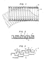
- Figs. 1 through 4 are views showing an embodiment according to the present invention. Although the outline of the arrangement shown in Figs. 1 through 4 has been described in the above introductory paragraph, the arrangement will be further described hereunder.
- an inner pipe wall B is formed such that a soft synthetic resin belt-like member B1 forming the inner pipe wall B is extruded in the form of a belt from a not-shown extruder under the condition of a temperature not lower than a softening point but not higher than a melting point of the synthetic resin.
- the belt-like member B1 is helically wound on a mandrel so as to be superimposed at its opposite side edge portions on succeeding wraps.
- the superimposed portions are pressed from their upper surfaces, as required, by a pressing roller so as to be fused and to be stuck to each other.
- an outer pipe wall A is formed from a hard synthetic resin belt-like member 1 composed in cross-section of a substantially linear base portion 2, an upward extending portion 3 continuing from the base portion 2 at its right side of the drawing, and a downwardly opened, substantially U-shaped portion 4 including another upward extending portion 41 continued from the base portion 2 at its left side in the drawing, a ceiling portion 42 horizontally extending left from the upward extending portion 41, and a downward extending portion 43 extending downwardly from the left end of the ceiling portion 42.
- the belt-like member 1 is separately formed and then successively wound in a helix onto an outer peripheral surface of the prepared inner pipe wall B.
- the belt-like member 1 is wound at a pitch such that an upper portion of the upwardly extending portion 3 of the preceding wrap of the belt-like member 1 is covered by the downwardly opened U-shaped portion 4 of the succeeding wrap of the belt-like member 1.
- the structure of the hard belt-like member 1 forming the outer pipe wall A as illustrated in the embodiment is featured in that its cross-section has the following properties.
- (1) The width W1 between the upwardly extending portion 41 and the downwardly extending portion 43 and the width W2 between the upwardly extending portion 3 and the upward extending portion 41 of the hard belt-like member 1 are set to have a relationship in that W1 approximately equals W2.
- the height h1 between the lower surface of the base portion 2 and the upper surface of the ceiling portion 42, the length h2 of the downwardly extending portion 43, and the height h3 of the upwardly extending portion 3 of the belt-like member 1, are set to have relationships that h1 is greater than h2 and h2 is approximately equal to h3.
- the height h1, the length h2 and the thickness t2 of the base portion 2, of the hard belt-like member 1 are set to have a relationship that h1 is equal to or greater than the sum of h2 and t2.
- the height h1, the height h3 and the thickness t1 of the ceiling portion 42, of the hard belt-like member 1 are set to have a similar relationship that h1 is equal to or greater than the sum of h3 and t1.
- the downwardly opened U-shaped portion 4 of the hard belt-like member is U-shaped, but may be such a downwardly opened semi-circular form, as shown in Fig. 15, or other various kinds of forms as required.
- W1 in the relationship between the width W1 between the upward extending portion 41 and the downward extending portion 43 and the width W2 between the upward extending portion 3 and the upward extending portion 41 of the hard belt-like member 1, it is not always necessary that W1 be approximately equal to W2. Instead W1 may be less than or greater than W2.
- Fig. 5 is a view showing another embodiment which is arranged such that the upward extending portion 3, the upward extending portion 41, and the downward extending portion 43 of the hard belt-like member 1 shown in the above-mentioned embodiment are slanted in one direction (to the left in the drawing in this embodiment).
- the hard belt-like member 1 forming the outer pipe wall A is formed substantially in the same shape as that of the hard belt-like member 1 shown in the embodiment illustrated in Figs. 1 through 4.
- the hard belt-like member 1 is formed by coating a metal band member 11 with synthetic resin 12.
- the outer pipe wall A is formed such that the hard belt-like member 1 is successively wound as a helix on the outer peripheral surface of the inner pipe wall B formed by helically winding a soft synthetic belt-like member B1.
- the winding of the outer pipe wall A is such that the base portion 2 is brought into contact and fused with the outer peripheral surface of the inner pipe wall B only at the lower surface of the base portion 2.
- a flat soft synthetic resin belt-like member C1 for forming a coating pipe wall C is separately extruded from a not-shown extruder and is helically wound on the outer periphery of the outer pipe wall A such that the opposite edge portions of the belt-like member C1 are superimposed one on the other.
- the superimposed portions may be pressed by a pressing roller to be fused with each other as well as to the outer peripheral surface of the ceiling portion 42 of the hard belt-like member 1.
- Fig. 9 shows another embodiment in which a hard belt-like member 1 is made only of a hard synthetic resin material and is arranged such that an upper end of an upwardly extending portion 3 and a lower end of a downward extending portion 43 are respectively bent toward each other and to respective upward extending portions 41.
- Fig. 11 shows a further embodiment having such an arrangement that the upwardly extending portion 3, the upward extending portion 41, and the downwardly extending portion 3, the upwardly extending portion 41, are all slanted in one direction (to the left in the drawing).
- Figs. 11 through 12 show other embodiments in which the upwardly extending portion 3 and the downwardly extending portion portion 43 are shaped to be hollow triangles (Fig. 11), or in which each of an upwardly extending portion 3 and a downwardly extending portion 43 is shaped as an inverted triangle or an inverted trapezoid (Fig. 12).
- the upwardly extending portion 41 is slanted right in the drawing.
- Fig. 13 and 14 show further embodiments in each of which an upwardly extending portion 41 is slanted to left, and an upwardly extending portion 3 and a downwardly extending portion 43 are also slanted in the same direction as the upward extending of the upward extending portion 41, similarly to the embodiments shown in Figs. 5 and 10. Also, in these embodiments, the respective ends of the upward extending portions 3 and the downward extending portions 43 rounded (Fig. 13) or square (Fig. 14) respectively.
- the thickness of a coating pipe wall C is made thinner than that of an inner pipe wall B, and in the embodiment of Fig. 14 both the inner pipe wall B and the coating pipe wall C is made to be in a form of a thin film.
- the hard belt-like member 1 shown in each of the embodiments of Figs. 10 through 12 and 15, is partially internally provided with a metal band 11.
- the metal band member 11 is internally provided to extend from a base portion of the upwardly extending portion 3 to a base portion of the downwardly extending portion 43.
- the metal band 11 extends in a Z-shaped portion along the base portion 2, the upwardly extending portion 41, and the ceiling portion 42.
- the metal band 11 extends in a U-shaped portion along the upwardly extending portion 3, the base portion 2, and the upwardly extending portion 41.
- the metal belt 11 extends only in the base portion 2.
- the inner pipe wall B nor the coating pipe wall C according to the present invention necessarily needs to be made by helically winding a belt-like member as illustrated in each of the above-mentioned embodiments, but may be instead cylindrically extruded.
- the relative positional relationship between the fused portion and the position where the hard belt-like member 1 is helically wound is not particularly limited, it is advantageous to have such an arrangement that the base portion 2 of the hard belt-like member 1 is superimposed on the fusing portion of the inner pipe wall B (the belt-like member B1) and that the coating pipe wall C (the belt-like member C1) is superimposed on the ceiling portion 42.
- the advantage is that the fusing can be more firmly performed.
- the hard belt-like member 1 and/or the inner pipe wall B and the coating pipe wall C may be made of a synthetic resin material in a group of polyolefin such as polyethylene, polypropylene, or the like, or of another synthetic resin material in a group of vinyl chloride.
- the hard belt-like member 1 may be made of fiber resin-forced composite resin (FRP) which is made by reinforcing synthetic resin with very strong fibers such as whisker, glass, boron, carbon, alumina (Al2O3), silicon carbide (SiC) or the like hard rubber, or fiber reinforced rubber (FRR) which is made by reinforcing rubber with such very strong fibers, as described above.
- FRP fiber resin-forced composite resin
- the hard belt-like member 1 may be formed with a metal band plate.
- the hard belt-like member 1 may be formed with a metal band plate lined on its inner and outer surfaces with a synthetic resin material or a rubber material.
- the metal band plate may be formed of a punched metal in which a number so small holes are bored.
- the pipes can be laid along a curved path owing to the capability of expansion and contradiction of the hard outer pipe wall and the flexibility of the inner pipe wall during the pipe laying (as shown by two-dotted chain lines in Figs. 1 and 6).
- the hard pipe according to the present invention has such advantages that even if concave portions are formed in the hard belt-like member when the pipe is stretched or bent, the outer peripheral portion is coated with the coating pipe wall, so that there is no fear that external materials such as stones, soil, or the like, can come into the concave portions. Such materials would prevent the pipe from changing its shape into a contracted state.
- the coating pipe wall makes it possible to use the pipe conveniently and more stably as a pipe arranged on or above the ground or as a pipe to be embedded under the ground.
Abstract
A flexible hard pipe in which over a soft inner pipe wall (B) a hard belt-like member (A) is helically wound. The belt-like member has a double-hook shape in which a flat inner surface is fused to the inner pipe wall. A raised hook portion overlaps a hook portion of the fused portion of a neighboring wrap.
Description
- The present invention relates to flexible hard pipes which are pipes to be used mainly for transporting air and water, for protecting cables, or the like, and which are pressure-containing pipes adapted to be used on or above the ground, or buried under ground.
- The present invention particularly relates to hard pipes which, in spite of their pressure-containing property, are flexible so as to facilitate pipe laying and the transportation of pipes even when the pipes are buried underground and receive externally exerted pressure or are used as pipes carrying high-pressure fluid.
- As conventional hard pipes, there are known not only drawn pipes but also metal pipes which are formed such that a belt-like member is helically wound with its side edges abutted and seam-connected with each other by welding or the like. On the other hand, there are also pipes which are galvanized or the like or which are lined with a synthetic resin material over their inner peripheral surfaces so as to maintain an anti-corrosion property. Further, there have been generally used synthetic resin pipes containing no metal, such as so-called vinyl chloride pipes, which are extruded and molded from only a hard vinyl chloride material, or the like. Further, synthetic resin pipes have been already widely used which are formed such that a belt-like member made of synthetic resin is helically wound and opposite side edges thereof are superimposed and fused with each other.
- However, an enormous investment in plant and equipment is required in manufacturing the well known drawn pipes, and much trouble and cost and required in seam-welding the latter seam-connected metal pipes. Significant equipment and cost must be required in galvanizing and in lining with synthetic resin. Particularly, it has been technically difficult to uniformly apply anti-corrosion treatment on the entirety of the inner surface of elongated pipes. Further, the synthetic resin pipes in which pipe bodies are formed by successively winding a synthetic resin belt-like member have superior advantages in that the pipes are light so that transportation is facilitated when compared with the pipes made of metal. Furthermore, anti-corrosion treatment is unnecessary. However, such wound synthetic resin pipes have such disadvantages that yield strength relative to tensile strength in the axial direction of pipe is not always sufficient so that the pipes are stretched in the axial direction of pipe when a high-pressure fluid is passed through the pipes and are apt to lack compressive strength against external pressure, so that the pipes did not always have enough strength for use for transmitting high-pressure fluid or for the purpose of being embedded underground.
- An object of the present invention is to provide a hard pipe in which a synthetic resin material apt to lack anti-squeezing (compressive) strength as well as anti-stretching (tensile), strength is used, alone or together with a metal material. In such a pipe, the above-mentioned problems caused in the synthetic resin pipes of the kind as described above are solved, so that the pipes are superior in compressive strength as well as tensile strength, the pipes can be widely used for transmitting high-pressure fluid or for the purpose of being embedded underground. Nonetheless, the pipes are flexible to thereby make it possible to bend the pipes in arranging the pipes.
-
- Figs. 1 through 4 are views showing an embodiment of the pipe according to the present invention, in which Fig. 1 is a partly cut-away front view of the pipe, Fig. 2 is a cross-section showing the arrangement of pipe walls, Fig. 3 is an exploded cross-section of the pipe wall arrangement, and Fig. 4 is an enlarged cross-section of the hard belt-like member;
- Fig. 5 is an enlarged cross-section showing the pipe wall arrangement of another embodiment;
- Figs. 6 through 8 are view showing a further embodiment, in which Fig. 6 is a partly cut-away front view of the pipe, Fig. 7 is an enlarged cross-section of the pipe wall arrangement, and Fig. 8 is an exploded cross-section of the same; and
- Figs. 9 through 15 are enlarged cross-sections of pipe wall arrangements in other embodiments respectively.
- The present invention relates to a flexible hard pipe which can extremely easily and surely achieve the above-mentioned object. Referring to Figs. 1 through 4 illustrating an embodiment of the present invention, the hard pipe according to the present invention is provided with two main inner and outer parts, that is, an inner pipe wall B made of a soft synthetic resin material and an outer pipe wall A constituted by a belt-
like member 1 made of a hard material. The outer pipe wall A is helically wound on an outer periphery of the inner pipe wall B and is integrally fused with the inner pipe wall B. The hard belt-like material 1, as shown in Fig. 3, has such a cross-sectional shape that is composed of a substantiallylinear base portion 2, an upward extendingportion 3 continuing from one side edge of thebase portion 2, and a downwardly opening, substantiallyU-shaped portion 4. The downwardly opened substantially U-shapedportion 4 is composed of another upward extendingportion 41 continued from the other side edge portion of thebase portion 2, aceiling portion 42, and a downward extendingportion 43. The belt-like member 1 is in contact and fused with the outer periphery of the inner pipe wall B only at a lower surface of thebase portion 2 of the hard belt-like material 1. - The hard pipe having such a structure as described above can be arranged in a building or in a factory, or embedded underground, or can be used fluid flow through the pipe, or for enclosing wires or the like passing through the pipe.
- Referring to the drawings, specific embodiments of the present invention will be described hereunder.
- First, materials to be used will be described. Synthetic rubber, a mixture of synthetic resin and synthetic rubber, synthetic resin materials or the like in a group of vinyl chloride, a group of polyolefin such as polyethylene, polypropylene, etc., are selectively used as a synthetic resin material for forming both the soft inner and the hand outer pipe walls A and B in accordance with the purpose of use. Further, the hardness of each of the hard and soft materials is suitably selected by adjusting the plasticizer or the like.
- For example, with respect to the pipes arranged in a factory for use for transporting chemicals or the like, consideration is made such that a chemical-proof resin to be used as the synthetic resin material for forming an inner pipe wall B is selected in accordance with the kind of chemicals to be conveyed. A weatherproof resin which is resistant against deterioration owing to changes of external weather, temperature, or the like, is used as the synthetic resin material for the outer pipe wall A (or as a coating pipe wall C in embodiments as illustrated in Figs. 6 through 15 which will be described later). As illustrated in the embodiment shown in Figs. 6 through 8, a resin-coated metal belt-
like member 1, which is made by coating ametal band 11 with asynthetic resin 12, may be used as the hard belt-like member for forming the outer pipe wall A. Steel plates, stainless steel plates, iron plates, and other metal plates are desirably selectively used as a material for such ametal band member 11 in accordance with the use of the pipes to be formed. Then plates having a thickness within a range of about 0.3 to 3 mm are suitably selected taking into consideration the diameter of the pipes to be formed, the externally and internally applied pressure to be withstood by the pipes, the purpose and place of use of the pipes, and so on. Further, themetal band member 11 may be not only a flat belt-like one but a punched metal one in which a number of small holes are bored. Further, a bandage-like belt member made by knitting metal wires in the form of a net may be used as themetal band member 11. - Figs. 1 through 4 are views showing an embodiment according to the present invention. Although the outline of the arrangement shown in Figs. 1 through 4 has been described in the above introductory paragraph, the arrangement will be further described hereunder. As shown in Fig. 3, an inner pipe wall B is formed such that a soft synthetic resin belt-like member B₁ forming the inner pipe wall B is extruded in the form of a belt from a not-shown extruder under the condition of a temperature not lower than a softening point but not higher than a melting point of the synthetic resin. The belt-like member B₁ is helically wound on a mandrel so as to be superimposed at its opposite side edge portions on succeeding wraps.The superimposed portions are pressed from their upper surfaces, as required, by a pressing roller so as to be fused and to be stuck to each other.
- Then, an outer pipe wall A is formed from a hard synthetic resin belt-
like member 1 composed in cross-section of a substantiallylinear base portion 2, an upward extendingportion 3 continuing from thebase portion 2 at its right side of the drawing, and a downwardly opened, substantially U-shapedportion 4 including another upward extendingportion 41 continued from thebase portion 2 at its left side in the drawing, aceiling portion 42 horizontally extending left from the upward extendingportion 41, and a downward extendingportion 43 extending downwardly from the left end of theceiling portion 42. The belt-like member 1 is separately formed and then successively wound in a helix onto an outer peripheral surface of the prepared inner pipe wall B. Only the lower surface of thebase portion 2 is caused to abut on and to be fused with the outer peripheral surface of the inner pipe wall B. Furthermore, the belt-like member 1 is wound at a pitch such that an upper portion of the upwardly extendingportion 3 of the preceding wrap of the belt-like member 1 is covered by the downwardly opened U-shapedportion 4 of the succeeding wrap of the belt-like member 1. - As shown in Fig. 4, the structure of the hard belt-
like member 1 forming the outer pipe wall A as illustrated in the embodiment is featured in that its cross-section has the following properties. (1) The width W₁ between the upwardly extendingportion 41 and the downwardly extendingportion 43 and the width W₂ between the upwardly extendingportion 3 and the upward extendingportion 41 of the hard belt-like member 1 are set to have a relationship in that W₁ approximately equals W₂. (2) The height h₁ between the lower surface of thebase portion 2 and the upper surface of theceiling portion 42, the length h₂ of the downwardly extendingportion 43, and the height h₃ of the upwardly extendingportion 3 of the belt-like member 1, are set to have relationships that h₁ is greater than h₂ and h₂ is approximately equal to h₃. (3) The height h₁, the length h₂ and the thickness t₂ of thebase portion 2, of the hard belt-like member 1, are set to have a relationship that h₁ is equal to or greater than the sum of h₂ and t₂. (4) The height h₁, the height h₃ and the thickness t₁ of theceiling portion 42, of the hard belt-like member 1, are set to have a similar relationship that h₁ is equal to or greater than the sum of h₃ and t₁. - It is not necessary that the downwardly opened U-shaped
portion 4 of the hard belt-like member is U-shaped, but may be such a downwardly opened semi-circular form, as shown in Fig. 15, or other various kinds of forms as required. As is easily understood from Fig. 15, in the relationship between the width W₁ between the upward extendingportion 41 and the downward extendingportion 43 and the width W₂ between the upward extendingportion 3 and the upward extendingportion 41 of the hard belt-like member 1, it is not always necessary that W₁ be approximately equal to W₂. Instead W₁ may be less than or greater than W₂. - Fig. 5 is a view showing another embodiment which is arranged such that the upward extending
portion 3, the upward extendingportion 41, and the downward extendingportion 43 of the hard belt-like member 1 shown in the above-mentioned embodiment are slanted in one direction (to the left in the drawing in this embodiment). - Next, referring to Figs. 6 through 15, description will be made as to various embodiments each having such an arrangement that a coating pipe wall C is formed on the outer peripheral surface of an outer pipe wall A to cover the outer pipe wall A. According to the present invention, however, it is not fundamentally necessary to provide the coating pipe wall C as shown in the above-mentioned embodiments. Therefore, it will be appreciated that the description of various embodiments which will be made hereunder apply as well to corresponding embodiments having no coating pipe wall C.
- In the embodiment shown in Figs. 6 through 8, the hard belt-
like member 1 forming the outer pipe wall A is formed substantially in the same shape as that of the hard belt-like member 1 shown in the embodiment illustrated in Figs. 1 through 4. As mentioned previously, the hard belt-like member 1 is formed by coating ametal band member 11 withsynthetic resin 12. In the same manner as in the embodiment illustrated in Figs. 1 through 4, the outer pipe wall A is formed such that the hard belt-like member 1 is successively wound as a helix on the outer peripheral surface of the inner pipe wall B formed by helically winding a soft synthetic belt-like member B₁. The winding of the outer pipe wall A is such that thebase portion 2 is brought into contact and fused with the outer peripheral surface of the inner pipe wall B only at the lower surface of thebase portion 2. A flat soft synthetic resin belt-like member C₁ for forming a coating pipe wall C is separately extruded from a not-shown extruder and is helically wound on the outer periphery of the outer pipe wall A such that the opposite edge portions of the belt-like member C₁ are superimposed one on the other. Depending upon requirements, the superimposed portions may be pressed by a pressing roller to be fused with each other as well as to the outer peripheral surface of theceiling portion 42 of the hard belt-like member 1. - Fig. 9 shows another embodiment in which a hard belt-
like member 1 is made only of a hard synthetic resin material and is arranged such that an upper end of an upwardly extendingportion 3 and a lower end of a downward extendingportion 43 are respectively bent toward each other and to respective upward extendingportions 41. - Fig. 11 shows a further embodiment having such an arrangement that the upwardly extending
portion 3, the upward extendingportion 41, and the downwardly extendingportion 3, the upwardly extendingportion 41, are all slanted in one direction (to the left in the drawing). Figs. 11 through 12 show other embodiments in which the upwardly extendingportion 3 and the downwardly extendingportion portion 43 are shaped to be hollow triangles (Fig. 11), or in which each of an upwardly extendingportion 3 and a downwardly extendingportion 43 is shaped as an inverted triangle or an inverted trapezoid (Fig. 12). In the embodiment of Fig. 12, the upwardly extendingportion 41 is slanted right in the drawing. - Fig. 13 and 14 show further embodiments in each of which an upwardly extending
portion 41 is slanted to left, and an upwardly extendingportion 3 and a downwardly extendingportion 43 are also slanted in the same direction as the upward extending of the upward extendingportion 41, similarly to the embodiments shown in Figs. 5 and 10. Also, in these embodiments, the respective ends of the upward extendingportions 3 and the downward extendingportions 43 rounded (Fig. 13) or square (Fig. 14) respectively. In the embodiment of Fig. 13 the thickness of a coating pipe wall C is made thinner than that of an inner pipe wall B, and in the embodiment of Fig. 14 both the inner pipe wall B and the coating pipe wall C is made to be in a form of a thin film. - The hard belt-
like member 1 shown in each of the embodiments of Figs. 10 through 12 and 15, is partially internally provided with ametal band 11. In the embodiment of Fig. 10, themetal band member 11 is internally provided to extend from a base portion of the upwardly extendingportion 3 to a base portion of the downwardly extendingportion 43. In the embodiment of Fig. 11, themetal band 11 extends in a Z-shaped portion along thebase portion 2, the upwardly extendingportion 41, and theceiling portion 42. In the embodiment of Fig. 12, themetal band 11 extends in a U-shaped portion along the upwardly extendingportion 3, thebase portion 2, and the upwardly extendingportion 41. In the embodiment of Fig. 15, themetal belt 11 extends only in thebase portion 2. Thus, it is not always necessary to use themetal band 11 over the whole region of the hard belt-like member 1 in such a manner as illustrated in the embodiment shown in Figs. 6 through 8, but may be desirably provided in accordance with the purpose of use of the hard pipe to be produced. - Neither the inner pipe wall B nor the coating pipe wall C according to the present invention necessarily needs to be made by helically winding a belt-like member as illustrated in each of the above-mentioned embodiments, but may be instead cylindrically extruded. Although for the helically wound hard belt-
like member 1, the relative positional relationship between the fused portion and the position where the hard belt-like member 1 is helically wound is not particularly limited, it is advantageous to have such an arrangement that thebase portion 2 of the hard belt-like member 1 is superimposed on the fusing portion of the inner pipe wall B (the belt-like member B₁) and that the coating pipe wall C (the belt-like member C₁) is superimposed on theceiling portion 42. The advantage is that the fusing can be more firmly performed. - The present invention can be built with the following materials. (1) The hard belt-
like member 1 and/or the inner pipe wall B and the coating pipe wall C may be made of a synthetic resin material in a group of polyolefin such as polyethylene, polypropylene, or the like, or of another synthetic resin material in a group of vinyl chloride. (2) The hard belt-like member 1 may be made of fiber resin-forced composite resin (FRP) which is made by reinforcing synthetic resin with very strong fibers such as whisker, glass, boron, carbon, alumina (Al₂O₃), silicon carbide (SiC) or the like hard rubber, or fiber reinforced rubber (FRR) which is made by reinforcing rubber with such very strong fibers, as described above. (3) The hard belt-like member 1 may be formed with a metal band plate. (4) The hard belt-like member 1 may be formed with a metal band plate lined on its inner and outer surfaces with a synthetic resin material or a rubber material. (5) The metal band plate may be formed of a punched metal in which a number so small holes are bored. - The typical embodiments according to the present invention have been described above. However, the present invention is not limited to only those embodiments, but can be suitably modified and carried out within a range in which the constituent features of the present invention are provided, the objects of the present invention can be achieved, and the effects which will be described later can be obtained.
- According to the present invention, as described above with respect to the embodiments and as stated in the introductory paragraph, a specially shaped hard belt-
like member 1 made of a hard material, perhaps including ametal band member 11, is partially integrally fused with an outer peripheral surface of an inner pipe wall B made of the soft synthetic resin material. Accordingly, the thus produced pipe is limited to not axially extend beyond a predetermined extent so that the tensile strength in the axial direction of the pipe is remarkably increased when compared with the conventional synthetic resin helical pipe. Further, the inner pressure withstanding strength of the pipe can be significantly increased, and necessary strength against externally exerted compressive force can be held sufficiently by the hard outer pipe wall. Thus, it is possible to obtain strong pressure-withstanding pipes which can be stably used as pipes for high-pressure fluid or pipes to be buried underground, in spite of its lightness. Further, in spite of having pressure-withstanding property, the pipes have a further extremely unique effect, which the conventional hard pipes have never been expected. Namely, the pipes can be laid along a curved path owing to the capability of expansion and contradiction of the hard outer pipe wall and the flexibility of the inner pipe wall during the pipe laying (as shown by two-dotted chain lines in Figs. 1 and 6). - In the case where the outer peripheral surface of the hard belt-
like member 1 is coated with a pipe wall C made of a soft synthetic resin material, as illustrated in the embodiments shown in Figs. 6 through 15, the hard pipe according to the present invention has such advantages that even if concave portions are formed in the hard belt-like member when the pipe is stretched or bent, the outer peripheral portion is coated with the coating pipe wall, so that there is no fear that external materials such as stones, soil, or the like, can come into the concave portions. Such materials would prevent the pipe from changing its shape into a contracted state. Thus the coating pipe wall makes it possible to use the pipe conveniently and more stably as a pipe arranged on or above the ground or as a pipe to be embedded under the ground.
Claims (18)
1. A flexible hard pipe, comprising an inner pipe wall made of a soft synthetic resin material and an outer pipe wall including a belt-like member made of a hard material helically wound on an outer periphery of said inner pipe wall and integrally fused with said inner pipe wall, said hard belt-like material having in cross-section a substantially linear base portion, at first radially outwardly extending portion continued from a first edge of said base portion, and a radially inwardly opened substantially U-shaped portion, said radially inwardly opened substantially U-shaped portion including a second radially outwardly extending portion continued from a second edge portion of said base portion, a ceiling portion connected at a first end to a radially outward part of said second radially outwardly extending portion, and a radially inwardly portion connected to a second end of said ceiling portion, said belt-like member being in contact and fused with the outer periphery of said inner pipe wall only at a lower surface of said base portion of said hard belt-like material
2. A flexible hard pipe having flexibility according to Claim 1, further comprising a coating pipe wall made of a hard synthetic resin material formed on an outer peripheral surface of said outer pipe wall such that an inner peripheral surface of said coating pipe wall is in contact and fused with an outer peripheral surface of said ceiling portion of said hard belt-like member.
3. A flexible hard pipe having flexibility according to Claim 1, in which a width (W₁) between said second radially outwardly extending portion and said radially inwardly extending portion is approximately equal to a width (W₂) between said first radially outwardly portion and said radially outwardly extending portion.
4. A flexible hard pipe having flexibility according to Claim 1, in which a width (W₁) between said second radially outwardly extending portion and said radially inwardly extending portion is less than a width (W₂) between said first radially outwardly portion and said radially outwardly extending portion.
5. A flexible hard pipe according to Claim 1, in which a height (h₁) between a lower surface of said base portion and an upper surface of said ceiling portion, a length (h₂) of said radially inwardly extending portion, and a height (h₃) of said first radially outwardly extending portion are such that h₁, is greater than h₂ and h₂ is approximately equal to h₃.
6. A flexible hard pipe according to Claim 1, in which a height (h₁) between a lower surface of said base portion and an upper surface of said ceiling portion a length (h₂) of said radially inwardly portion and a thicknss (t₂) of said base portion are such that h₁ is equal to or greater than the sum of h₂ and t₂,
7. A flexible hard pipe according to Claim 1, in which a height (h₁) between a lower surface of said base portion and an upper surface of said ceiling portion, a height (h₂) of said first radially outwardly extending portion, and a thickness (t₁) of said ceiling portion are such that h₁ is equal to or greater than the sum of h₃ and t₁.
8. A flexible hard pipe according to Claim 1, in which said hard belt-like member comprises a synthetic resin material in a group of polyolefin or in a group of vinyl chloride.
9. A flexible hard pipe according to Claim 1, in which said hard belt-like member comprises a fiber reinforced composite resin.
10. A flexible hard pipe according to Claim 1, in which said hard belt-like member comprises a hard rubber.
11. A flexible hard pipe according to Claim 1, in which said hard belt-like member is comprises a fiber reinforced composite rubber.
12. A flexible hard pipe according to Claim 1, in which said hard belt-like member comprises a belt-like metal plate.
13. A hard pipe according to Claim 1, in which said hard belt-like member comprises a metal band plate coated with a synthetic resin material or a rubber material on inner and outer surfaces of said metal band plate.
14. A hard pipe according to Claim 12, in which said metal band plate is a punched metal having a plurality of small holes bored therein.
15. A flexible hard pipe according to Claim 1, wherein said first and second radially outwardly extending portions and said radially inwardly extending portions extend in parallel at an angle inclined to a radius of said outer pipe wall.
16. A flexible hard pipe according to Claim 1, wherein each of said radially inwardly extending portion and said first radially outwardly extending portion has at a free end a portion extending toward said second radially outwardly extending portion.
a free end a portion extending toward said second radially outwardly extending portion.
a free end a portion extending toward said second radially outwardly extending portion.
17. A flexible, hard pipe according to claim 1, wherein each of said first radially outwardly extending portion and said radially inwardly extending portion has a triangular cross-section with a smaller width at a free end thereof.
18. A flexible hard pipe according to Claim 1, wherein each of said first radially outwardly extending portion and said radially inwardly extending portion has sa trapezoidal cross-section with a larger width at a free end thereof.
Applications Claiming Priority (4)
| Application Number | Priority Date | Filing Date | Title |
|---|---|---|---|
| JP61094/86U | 1986-04-23 | ||
| JP1986061094U JPS62172886U (en) | 1986-04-23 | 1986-04-23 | |
| JP12255086U JPH0331914Y2 (en) | 1986-08-08 | 1986-08-08 | |
| JP122550/86U | 1986-08-08 |
Publications (1)
| Publication Number | Publication Date |
|---|---|
| EP0246360A1 true EP0246360A1 (en) | 1987-11-25 |
Family
ID=26402139
Family Applications (1)
| Application Number | Title | Priority Date | Filing Date |
|---|---|---|---|
| EP86117648A Withdrawn EP0246360A1 (en) | 1986-04-23 | 1986-12-18 | Flexible hard pipe |
Country Status (3)
| Country | Link |
|---|---|
| US (1) | US4862924A (en) |
| EP (1) | EP0246360A1 (en) |
| KR (1) | KR890005304B1 (en) |
Cited By (7)
| Publication number | Priority date | Publication date | Assignee | Title |
|---|---|---|---|---|
| EP0436772A2 (en) * | 1990-01-12 | 1991-07-17 | Witzenmann GmbH Metallschlauch-Fabrik Pforzheim | Pipe component having the shape of a corrugated hose or a bellow |
| US5226941A (en) * | 1991-04-24 | 1993-07-13 | Vorwerk & Co. Interholding Gmbh | Dust filter bag |
| US5316047A (en) * | 1988-12-27 | 1994-05-31 | Shiro Kanao | Pressure-resistant helical corrugated pipe |
| WO2008041188A1 (en) | 2006-10-05 | 2008-04-10 | Nxp B.V. | Tunnel field effect transistor |
| JP2009036371A (en) * | 2007-06-28 | 2009-02-19 | Wellstream Internatl Ltd | Flexible body |
| EP3056781A1 (en) * | 2015-02-10 | 2016-08-17 | Witzenmann GmbH | Strip wound hose |
| US10030793B2 (en) | 2011-03-25 | 2018-07-24 | Ge Oil & Gas Uk Limited | Flexible pipe body and method of producing same |
Families Citing this family (46)
| Publication number | Priority date | Publication date | Assignee | Title |
|---|---|---|---|---|
| JP2767427B2 (en) * | 1988-07-05 | 1998-06-18 | 三菱樹脂株式会社 | Corrugated pipe manufacturing method |
| US5184649A (en) * | 1988-11-26 | 1993-02-09 | Shiro Kanao | Pressure-resistant helical corrugated pipe |
| JP2544194B2 (en) * | 1988-11-26 | 1996-10-16 | 史朗 金尾 | Pressure resistant spiral corrugated tube |
| JPH02176291A (en) * | 1988-12-27 | 1990-07-09 | Shiro Kanao | Pressureproof helical corrugated pipe |
| US5193588A (en) * | 1988-12-27 | 1993-03-16 | Shiro Kanao | Pressure-resistant helical corrugated pipe |
| US5284185A (en) * | 1988-12-27 | 1994-02-08 | Shiro Kanao | Pressure-resistant helical corrugated pipe and method of producing same |
| JPH0658158B2 (en) * | 1988-12-27 | 1994-08-03 | 史朗 金尾 | Pressure resistant spiral corrugated tube |
| US5143123A (en) * | 1989-08-18 | 1992-09-01 | Simula, Inc. | Cylindrical armor |
| US5259418A (en) * | 1991-03-18 | 1993-11-09 | Hamrick James C | Heat reshapeable regid conduit |
| US5228479A (en) * | 1991-06-17 | 1993-07-20 | Tru-Flex Metal Hose Corporation | Multi-layered flexible piping and method and machine for forming same |
| JP3118579B2 (en) * | 1992-12-09 | 2000-12-18 | 金尾 茂樹 | Pressure-resistant synthetic resin tube |
| US5443100A (en) * | 1994-07-13 | 1995-08-22 | The United Electric Company Of Ohio | Low pressure and vacuum hose |
| US5645110A (en) * | 1994-12-01 | 1997-07-08 | Nobileau; Philippe | Flexible high pressure pipe |
| US5893681A (en) * | 1997-01-06 | 1999-04-13 | Senior Engineering Investments Ag | Flexible pipe having a flexible wrap applied thereto and method for attaching the wrap |
| US5884670A (en) * | 1997-05-06 | 1999-03-23 | Tigers Poymer Corporation | Synthetic resin tube and producing method thereof |
| US6742545B2 (en) | 1998-12-21 | 2004-06-01 | Parker-Hannifin Corporation | Hose construction |
| WO2000037841A1 (en) | 1998-12-21 | 2000-06-29 | Parker-Hannifin Corporation | Collapse-resistant hose construction |
| JP4510969B2 (en) * | 1999-12-24 | 2010-07-28 | 株式会社共和 | Rubber pipe for connecting refrigerant circulation pipe and method for manufacturing the same |
| US20010006712A1 (en) * | 1999-12-27 | 2001-07-05 | Motoshige Hibino | Hose of impermeability and a process for manufacturing the same |
| JP2001254876A (en) * | 2000-03-08 | 2001-09-21 | Totaku Kogyo Kk | Flexible hose |
| FR2808070B1 (en) * | 2000-04-21 | 2002-06-07 | Coflexip | FLEXIBLE METAL TUBE WITH BOX AND FLEXIBLE CONDUIT COMPRISING SUCH A METAL TUBE |
| FR2817318B1 (en) * | 2000-11-24 | 2002-12-27 | Coflexip | FLEXIBLE TUBULAR CONDUCT |
| KR100486150B1 (en) * | 2002-01-15 | 2005-04-29 | 정인선 | Spiral Hose Using Polyethylene |
| WO2003062697A1 (en) * | 2002-01-17 | 2003-07-31 | Wilson Michael W | Interlocked strip structure |
| JP2004215494A (en) * | 2002-12-18 | 2004-07-29 | Sumitomo Electric Ind Ltd | Communication cable and protective tube for communication lines |
| CN100375203C (en) * | 2002-12-18 | 2008-03-12 | 住友电气工业株式会社 | Protective tube for communication cable and communication wire |
| US7484535B2 (en) * | 2005-03-14 | 2009-02-03 | Advanced Drainage Systems, Inc. | Corrugated pipe with outer layer |
| US8733405B2 (en) | 2005-03-14 | 2014-05-27 | Advanced Drainage Systems, Inc. | Corrugated pipe with outer layer |
| US7156128B1 (en) * | 2005-06-21 | 2007-01-02 | Kanaflex Corporation | Synthetic resin pipe |
| KR100586638B1 (en) * | 2005-08-10 | 2006-06-08 | 주식회사 대흥종합엔지니어링건축사사무소 | Curved Drainpipe and Method of Construction for Road Zone |
| CA2622692C (en) | 2007-02-26 | 2015-10-06 | Advanced Drainage Systems, Inc. | Defined ratio dual-wall pipe die |
| CA2622695C (en) | 2007-02-26 | 2015-11-03 | Advanced Drainage Systems, Inc. | Pipe extrusion die flow path apparatus and method |
| US8820801B2 (en) | 2007-11-16 | 2014-09-02 | Advanced Drainage System, Inc. | Multi-wall corrugated pipe couplings and methods |
| US8820800B2 (en) | 2007-11-16 | 2014-09-02 | Advanced Drainage Systems, Inc. | Multi-wall corrugated pipe couplings and methods |
| US8114324B2 (en) | 2008-10-14 | 2012-02-14 | Advanced Drainage Systems, Inc. | Apparatus and method for pressing an outer wall of pipe |
| US7988438B2 (en) | 2008-02-11 | 2011-08-02 | Advanced Drainage Systems, Inc. | Extrusion die vacuum seals |
| US8550807B2 (en) | 2008-05-28 | 2013-10-08 | Advanced Drainage Systems, Inc. | In-mold punch apparatus and methods |
| GB0818507D0 (en) * | 2008-10-09 | 2008-11-19 | Wellstream Int Ltd | Flexible pipe having pressure armour layer and components thereof |
| HUE031278T2 (en) * | 2009-01-28 | 2017-07-28 | Plastiflex Group | Flexible hose with smooth inner and/or outer wall |
| GB0922122D0 (en) | 2009-12-18 | 2010-02-03 | Wellstream Int Ltd | Flexible pipe having a carcass layer |
| GB0922121D0 (en) | 2009-12-18 | 2010-02-03 | Wellstream Int Ltd | Flexible pipe including thermal insulation |
| DE102011110219B4 (en) * | 2011-08-16 | 2013-03-14 | Boa Balg- Und Kompensatoren-Technologie Gmbh | A method for producing a winding tube, in particular Agraffschlauch and winding tube and flexible conduit member with a winding tube |
| EP3006800A4 (en) * | 2013-05-27 | 2017-03-08 | Kokusan Rasenkan Co. Ltd. | Flexible tube, flexible hose, and method for producing flexible tube |
| US9759354B2 (en) | 2015-06-05 | 2017-09-12 | Advanced Drainage Systems, Inc. | Pipe with an outer wrap |
| KR20220132612A (en) * | 2020-01-28 | 2022-09-30 | 키스톤 타워 시스템스, 인코포레이티드 | Reinforcement of tubular structures |
| CN112693759A (en) * | 2020-12-15 | 2021-04-23 | 洛阳恒基石化科技有限公司 | Flexible drain pipe of oil tank and production process of steel sleeve of flexible drain pipe |
Citations (6)
| Publication number | Priority date | Publication date | Assignee | Title |
|---|---|---|---|---|
| DE164391C (en) * | ||||
| US2014368A (en) * | 1933-12-07 | 1935-09-17 | Blundell Alfred | Silencing device |
| DE1909468U (en) * | 1964-10-29 | 1965-02-04 | Rhein Plastic Rohr G M B H | THERMOPLASTIC PLASTIC TUBE. |
| DE1921293A1 (en) * | 1969-04-25 | 1970-11-12 | Adrema Werke Gmbh | Device for automatically ejecting printed matter from printing machines, in particular address printing machines |
| US4007761A (en) * | 1975-10-30 | 1977-02-15 | Union Carbide Corporation | Prepackaged shirred tubular casing article |
| FR2513346A1 (en) * | 1981-09-18 | 1983-03-25 | Kanao Shiro | CORRUGATED HOSE IN DOUBLE WALL SYNTHETIC RESIN |
Family Cites Families (6)
| Publication number | Priority date | Publication date | Assignee | Title |
|---|---|---|---|---|
| US3204666A (en) * | 1962-12-17 | 1965-09-07 | Calumet & Hecla | Helically wound flexible hose |
| US4383555A (en) * | 1976-04-20 | 1983-05-17 | Plastiflex Company International | Helically wound hose from co-extruded profile with reinforcing ribs interlocked at adjacent convolutions |
| US4140154A (en) * | 1976-05-13 | 1979-02-20 | Shiro Kanao | Flexible hose |
| EP0039495B1 (en) * | 1980-05-06 | 1984-07-18 | Hans Grohe GmbH & Co. KG | Flexible reinforced plastic hose, in particular shower hose, and its method of manufacture |
| US4403631A (en) * | 1981-05-12 | 1983-09-13 | Abdullaev Gasan M B O | Flexible pipe |
| DE3246247A1 (en) * | 1982-12-14 | 1984-06-14 | Siemens AG, 1000 Berlin und 8000 München | DOUBLE-WALLED, FLEXIBLE HOSE |
-
1986
- 1986-09-10 KR KR8607576A patent/KR890005304B1/en not_active IP Right Cessation
- 1986-12-18 EP EP86117648A patent/EP0246360A1/en not_active Withdrawn
-
1989
- 1989-03-08 US US07/320,838 patent/US4862924A/en not_active Expired - Lifetime
Patent Citations (6)
| Publication number | Priority date | Publication date | Assignee | Title |
|---|---|---|---|---|
| DE164391C (en) * | ||||
| US2014368A (en) * | 1933-12-07 | 1935-09-17 | Blundell Alfred | Silencing device |
| DE1909468U (en) * | 1964-10-29 | 1965-02-04 | Rhein Plastic Rohr G M B H | THERMOPLASTIC PLASTIC TUBE. |
| DE1921293A1 (en) * | 1969-04-25 | 1970-11-12 | Adrema Werke Gmbh | Device for automatically ejecting printed matter from printing machines, in particular address printing machines |
| US4007761A (en) * | 1975-10-30 | 1977-02-15 | Union Carbide Corporation | Prepackaged shirred tubular casing article |
| FR2513346A1 (en) * | 1981-09-18 | 1983-03-25 | Kanao Shiro | CORRUGATED HOSE IN DOUBLE WALL SYNTHETIC RESIN |
Non-Patent Citations (1)
| Title |
|---|
| PATENT ABSTRACTS OF JAPAN, vol. 1, no. 14 (M-76), 22nd March 1977, page 1062 M 76; & JP - A - 51 126 519 (TOTAKU KOGYO) 04-11-1976 * |
Cited By (16)
| Publication number | Priority date | Publication date | Assignee | Title |
|---|---|---|---|---|
| US5316047A (en) * | 1988-12-27 | 1994-05-31 | Shiro Kanao | Pressure-resistant helical corrugated pipe |
| US5573038A (en) * | 1988-12-27 | 1996-11-12 | Kanao; Shiro | Pressure-resistant helical corrugated pipe including a thin metal reinforcing plate |
| EP0436772A2 (en) * | 1990-01-12 | 1991-07-17 | Witzenmann GmbH Metallschlauch-Fabrik Pforzheim | Pipe component having the shape of a corrugated hose or a bellow |
| EP0436772A3 (en) * | 1990-01-12 | 1991-12-11 | Witzenmann Gmbh Metallschlauch-Fabrik Pforzheim | Pipe component having the shape of a corrugated hose or a bellow |
| US5226941A (en) * | 1991-04-24 | 1993-07-13 | Vorwerk & Co. Interholding Gmbh | Dust filter bag |
| WO2008041188A1 (en) | 2006-10-05 | 2008-04-10 | Nxp B.V. | Tunnel field effect transistor |
| EP2056007A3 (en) * | 2007-06-28 | 2012-03-28 | Wellstream International Limited | Flexible Pipe |
| EP2056007A2 (en) | 2007-06-28 | 2009-05-06 | Wellstream International Limited | Flexible Pipe |
| JP2009036371A (en) * | 2007-06-28 | 2009-02-19 | Wellstream Internatl Ltd | Flexible body |
| AU2008202795B2 (en) * | 2007-06-28 | 2013-09-12 | Ge Oil & Gas Uk Limited | Flexible pipe body for a flexible pipe, method of manufacture and flexible pipe |
| US9079353B2 (en) | 2007-06-28 | 2015-07-14 | Ge Oil & Gas Uk Limited | Flexible pipe |
| US9090019B2 (en) | 2007-06-28 | 2015-07-28 | Ge Oil & Gas Uk Limited | Flexible pipe |
| US10030793B2 (en) | 2011-03-25 | 2018-07-24 | Ge Oil & Gas Uk Limited | Flexible pipe body and method of producing same |
| EP3056781A1 (en) * | 2015-02-10 | 2016-08-17 | Witzenmann GmbH | Strip wound hose |
| US9638359B2 (en) | 2015-02-10 | 2017-05-02 | Witzenmann Gmbh | Strip wound hose |
| EP3056781B1 (en) | 2015-02-10 | 2019-06-12 | Witzenmann GmbH | Strip wound hose |
Also Published As
| Publication number | Publication date |
|---|---|
| US4862924A (en) | 1989-09-05 |
| KR890005304B1 (en) | 1989-12-20 |
| KR870010352A (en) | 1987-11-30 |
Similar Documents
| Publication | Publication Date | Title |
|---|---|---|
| EP0246360A1 (en) | Flexible hard pipe | |
| US4800928A (en) | Flexible pipe | |
| US5573038A (en) | Pressure-resistant helical corrugated pipe including a thin metal reinforcing plate | |
| KR880000383Y1 (en) | Underground piping | |
| US4903735A (en) | Pipe usable particularly for transporting fluids and allowing the permeability to the fluids transported to be limited | |
| US5007462A (en) | Synthetic resin underground pipe having high pressure-withstanding capability | |
| US5383497A (en) | Flexible hose construction having an inner corrugated hose made of polymeric material | |
| CA2066257C (en) | Flexible hose constructions and methods of making the same | |
| US6889715B2 (en) | Flexible tubular member with sealed tape layer | |
| US4377186A (en) | Floating flexible tubes | |
| US5191916A (en) | Pressure-resistant helical corrugated pipe | |
| GB2117864A (en) | Non-kinking hose | |
| CA2245738A1 (en) | Flexible pipe with internal gasproof undulating metal tube | |
| US5360037A (en) | Diffusion-proof rubber hose having plastic memory | |
| US5385174A (en) | Pressure-resistant helical corrugated pipe | |
| US5284185A (en) | Pressure-resistant helical corrugated pipe and method of producing same | |
| US3799825A (en) | Hoses and pipes | |
| EP0969236A3 (en) | Kink resistant high pressure hose | |
| US5109889A (en) | Pressure-resistant helical corrugated pipe | |
| CA1087532A (en) | Hose construction and method of making same | |
| JPH0432548Y2 (en) | ||
| JPH0331914Y2 (en) | ||
| MXPA02006774A (en) | Flexible metal conduit. | |
| JPH0432549Y2 (en) | ||
| JPH07189588A (en) | Double structural steel pipe for propulsive excavating method |
Legal Events
| Date | Code | Title | Description |
|---|---|---|---|
| PUAI | Public reference made under article 153(3) epc to a published international application that has entered the european phase |
Free format text: ORIGINAL CODE: 0009012 |
|
| AK | Designated contracting states |
Kind code of ref document: A1 Designated state(s): DE ES FR GB |
|
| 17P | Request for examination filed |
Effective date: 19871210 |
|
| 17Q | First examination report despatched |
Effective date: 19881107 |
|
| STAA | Information on the status of an ep patent application or granted ep patent |
Free format text: STATUS: THE APPLICATION HAS BEEN WITHDRAWN |
|
| 18W | Application withdrawn |
Withdrawal date: 19910304 |
|
| R18W | Application withdrawn (corrected) |
Effective date: 19910304 |