EP0246344A1 - Ozone generating apparatus - Google Patents
Ozone generating apparatus Download PDFInfo
- Publication number
- EP0246344A1 EP0246344A1 EP86106921A EP86106921A EP0246344A1 EP 0246344 A1 EP0246344 A1 EP 0246344A1 EP 86106921 A EP86106921 A EP 86106921A EP 86106921 A EP86106921 A EP 86106921A EP 0246344 A1 EP0246344 A1 EP 0246344A1
- Authority
- EP
- European Patent Office
- Prior art keywords
- high voltage
- ground electrode
- ozonizer
- electrode tube
- open end
- Prior art date
- Legal status (The legal status is an assumption and is not a legal conclusion. Google has not performed a legal analysis and makes no representation as to the accuracy of the status listed.)
- Granted
Links
Images

Classifications
-
- C—CHEMISTRY; METALLURGY
- C01—INORGANIC CHEMISTRY
- C01B—NON-METALLIC ELEMENTS; COMPOUNDS THEREOF; METALLOIDS OR COMPOUNDS THEREOF NOT COVERED BY SUBCLASS C01C
- C01B13/00—Oxygen; Ozone; Oxides or hydroxides in general
- C01B13/10—Preparation of ozone
- C01B13/11—Preparation of ozone by electric discharge
-
- C—CHEMISTRY; METALLURGY
- C01—INORGANIC CHEMISTRY
- C01B—NON-METALLIC ELEMENTS; COMPOUNDS THEREOF; METALLOIDS OR COMPOUNDS THEREOF NOT COVERED BY SUBCLASS C01C
- C01B2201/00—Preparation of ozone by electrical discharge
- C01B2201/10—Dischargers used for production of ozone
- C01B2201/14—Concentric/tubular dischargers
-
- C—CHEMISTRY; METALLURGY
- C01—INORGANIC CHEMISTRY
- C01B—NON-METALLIC ELEMENTS; COMPOUNDS THEREOF; METALLOIDS OR COMPOUNDS THEREOF NOT COVERED BY SUBCLASS C01C
- C01B2201/00—Preparation of ozone by electrical discharge
- C01B2201/20—Electrodes used for obtaining electrical discharge
- C01B2201/22—Constructional details of the electrodes
Definitions
- This inventions relates to an ozone generating apparatus, and more particularly to an ozone generating apparatus which is compact and high in safety.
- Ozone generating apparatus are employed for obtaining ozone by the high voltage discharge in air.
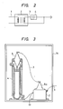
- Figure 2 shows the essential components of an ozone generating apparatus, wherein a high voltage transformer 2 is connected to a power source 1 for applying a very high voltage to an ozonizer 4 by a high voltage feeder line 3 which connects the transformer 2 to the ozonizer, and wherein a high voltage discharge occurs within the ozonizer.
- FIG. 3 illustrates an example of a conventional ozone generating apparatus.
- a housing 14 houses a high voltage transformer 2 and an ozonizer 4 which are fixedly mounted side by side and separate from each other.
- the ozonizer supports a high voltage bushing 5 within the upper, open end of the same.
- the bare high voltage bushing 5 is connected to a bushing 5a of the high voltage transformer 2 through a high voltage power feeder or line 3.
- an object of the present invention to eliminate the foregoing disadvantages and to provide an ozone generating apparatus which is compact and which is high in safety.
- the present invention is directed to an ozone generating apparatus comprising a housing, a high voltage transformer mounted within said housing and having a casing.
- An ozonizer is fixedly mounted within said housing, and a high voltage bushing is fixedly mounted to one end of said ozonizer and electrically connected to the transformer.
- said ozonizer comprising a cylindrical electrode tube having a closed end and an open end with said open end of said cylindrical electrode tube being fixedly mounted to the high voltage transformer casing and about the high voltage bushing.
- the preferred embodiment of the ozone generating apparatus of the present invention is composed of a series of components which are identical to that of the prior art apparatus of Figure 3 and identically numbered.
- the high voltage transformer 2 is fixedly mounted by way of its base 20 to the bottom portion 14a of housing 14 via bolts or screws as at 19.
- the high voltage transformer 2 is provided with a casing 15 of rectangular form, and mounted to the casing 15 and projecting upwardly therefrom at the center is a high voltage bushing 5a.
- Ozonizer 4 is of generally cylindrical form, being provided with a ground electrode tube 16 of elongated cylindrical shape having one end closed at 16a and having its opposite end 16b open and terminating in flanges 16c. Flanges 16c are fixedly mounted via fastening bolts 17 to casing 15 with the open end portion 16b of the ground electrode tube 16 facing downwardly.
- the high voltage bushing 5a which is fixed to the upper portion of casing 15, supports a conductive bar 6 which extends vertically upwardly and penetrates through the high voltage bushing 5a at its center to make appropriate connection with the high voltage transformer 2.
- a dielectric glass discharge tube 8 Internally of the ground electrode tube 16 of ozonizer 4 is a dielectric glass discharge tube 8, also of cylindrical shape and having one end 8a closed and having its opposite end 8b open. The diameter of the dielectric glass discharge tube 8 is smaller than that of the ground electrode tube 16. Tube 8 is insertably mounted within the inside of the ground electrode tube 16 and is fixedly positioned by means of spacers 10, near its closed upper end 8a and its open bottom end 8b. Thus, a space 18 is formed between the ground electrode tube 16 and the dielectric glass discharge tube 8.
- a conductive film 9 is formed on the inner surfaces of the electric glass discharge tube 8 and is connected to the projecting end of conductive bar 6 via a power supply brush 7 which spans across the conductive film 9.
- the ground electrode tube 16 is provided with an air inlet 12, and adjacent its upper closed end 6a, and an air outlet 12 is formed within the ground electrode tube 16 adjacent the flange 16c at the open end 16b of that tube.
- a ground bar 13 is provided for the ground electrode tube 16.
- a power source feeder or line 1 extends through housing 14 and connects to the high voltage transformer 2.
- the ozone generating apparatus of Figure 1 is highly compact because the high voltage transformer 2, the high voltage bushing 5a, and the ozonizer 4 are integral with each other, and in the illustrated embodiment, constituting a vertically stacked array.
- the operation of the same is very safe because the high voltage bushing 5a is accommodated within the ground metal of ground electrode tube 16 under conditions where it is surrounded by casing 15 and the ground electrode tube 16.
- ground electrode tube 16 and the high voltage bushing 5a constitute one pair of the illustrated embodiment, the invention is applicable to an ozone generating apparatus provided with two pairs or more of earth electrode tubes and high voltage bushings.
- each ground electrode tube 16 and electric glass discharge tube 8 may be of varied shape, so long as they can accommodate the high voltage bushing 5a therein.
- incidental equipment or ozone processing equipment for the ozone generating apparatus may be further accommodated in the housing 14 and the ozone generating apparatus itself may be oriented horizontally rather than vertically as shown, while being maintained in integrated fashion in accordance with Figure 1 and in contrast to that of Figure 3.
- the ozone generating apparatus of the present invention is characterized by the high voltage bushing being fixed to the casing of the high voltage transformer and inserted interiorly of the cylindrical shaped ozonizer through an open end thereof with the other end of the ozonizer being closed and the ozonizer and the casing of the voltage transformer being fixedly coupled to each other.
- the structural assembly is highly compact since the high voltage transformer is integrated directly with the ozonizer and the safety of operation is improved because the high voltage bushing is maintained internally of the ozonizer so as to obviate the exposure of any portion thereof.
Landscapes
- Chemical & Material Sciences (AREA)
- Organic Chemistry (AREA)
- Inorganic Chemistry (AREA)
- Oxygen, Ozone, And Oxides In General (AREA)
Abstract
Description
- This inventions relates to an ozone generating apparatus, and more particularly to an ozone generating apparatus which is compact and high in safety.
- Ozone generating apparatus are employed for obtaining ozone by the high voltage discharge in air. Figure 2 shows the essential components of an ozone generating apparatus, wherein a
high voltage transformer 2 is connected to apower source 1 for applying a very high voltage to anozonizer 4 by a highvoltage feeder line 3 which connects thetransformer 2 to the ozonizer, and wherein a high voltage discharge occurs within the ozonizer. - Figure 3 illustrates an example of a conventional ozone generating apparatus. A
housing 14 houses ahigh voltage transformer 2 and anozonizer 4 which are fixedly mounted side by side and separate from each other. The ozonizer supports ahigh voltage bushing 5 within the upper, open end of the same. The barehigh voltage bushing 5 is connected to a bushing 5a of thehigh voltage transformer 2 through a high voltage power feeder orline 3. - In the conventional ozone generating apparatus of Figure 3, there exists the problem that the
high voltage transformer 2 and theozonizer 4 are physically separate from each other, the result of which is that the apparatus is bulky. Additionally, this situation is highly dangerous because the high voltage power feeder orline 3 and thehigh voltage bushing 5 are relatively exposed. - It is, therefore, an object of the present invention to eliminate the foregoing disadvantages and to provide an ozone generating apparatus which is compact and which is high in safety.
- The present invention is directed to an ozone generating apparatus comprising a housing, a high voltage transformer mounted within said housing and having a casing. An ozonizer is fixedly mounted within said housing, and a high voltage bushing is fixedly mounted to one end of said ozonizer and electrically connected to the transformer. The improvement resides in said ozonizer comprising a cylindrical electrode tube having a closed end and an open end with said open end of said cylindrical electrode tube being fixedly mounted to the high voltage transformer casing and about the high voltage bushing.
-
- Figure 1 is a vertical elevational view, partially in section, of an ozone generating apparatus forming a preferred embodiment of the present invention.
- Figure 2 is an electrically schematic circuit diagram of the basic components of an ozone generating apparatus.
- Figure 3 is a vertical elevational view, partially in section, of a conventional ozone generating apparatus.
- Referring to Figure 1, the preferred embodiment of the ozone generating apparatus of the present invention is composed of a series of components which are identical to that of the prior art apparatus of Figure 3 and identically numbered. In Figure 1, the
high voltage transformer 2 is fixedly mounted by way of itsbase 20 to thebottom portion 14a ofhousing 14 via bolts or screws as at 19. Thehigh voltage transformer 2 is provided with acasing 15 of rectangular form, and mounted to thecasing 15 and projecting upwardly therefrom at the center is ahigh voltage bushing 5a. - Ozonizer 4 is of generally cylindrical form, being provided with a
ground electrode tube 16 of elongated cylindrical shape having one end closed at 16a and having its opposite end 16b open and terminating in flanges 16c. Flanges 16c are fixedly mounted viafastening bolts 17 tocasing 15 with the open end portion 16b of theground electrode tube 16 facing downwardly. The high voltage bushing 5a, which is fixed to the upper portion ofcasing 15, supports a conductive bar 6 which extends vertically upwardly and penetrates through thehigh voltage bushing 5a at its center to make appropriate connection with thehigh voltage transformer 2. - Internally of the
ground electrode tube 16 ofozonizer 4 is a dielectricglass discharge tube 8, also of cylindrical shape and having oneend 8a closed and having itsopposite end 8b open. The diameter of the dielectricglass discharge tube 8 is smaller than that of theground electrode tube 16. Tube 8 is insertably mounted within the inside of theground electrode tube 16 and is fixedly positioned by means ofspacers 10, near its closedupper end 8a and itsopen bottom end 8b. Thus, aspace 18 is formed between theground electrode tube 16 and the dielectricglass discharge tube 8. - A
conductive film 9 is formed on the inner surfaces of the electricglass discharge tube 8 and is connected to the projecting end of conductive bar 6 via a power supply brush 7 which spans across theconductive film 9. Theground electrode tube 16 is provided with anair inlet 12, and adjacent its upper closed end 6a, and anair outlet 12 is formed within theground electrode tube 16 adjacent the flange 16c at the open end 16b of that tube. Aground bar 13 is provided for theground electrode tube 16. - Further, a power source feeder or
line 1 extends throughhousing 14 and connects to thehigh voltage transformer 2. - In the apparatus described above, when a current is conducted from
transformer 2, viabushing 5a, to the dielectricglass discharge tube 8 through conductive bar 6 and the power supply brush 7, and a high voltage is applied across the inner surface of the electricglass discharge tube 8 and the inner surface of theground electrode tube 16, silent electrical discharge occurs therebetween so as to produce ozone from a part of the air fed intospace 18 fromair inlet 11, as indicated by arrow A, while ozonized air is removed fromoutlet 12, as indicated by arrow Aʹ. - As may be appreciated, the ozone generating apparatus of Figure 1 is highly compact because the
high voltage transformer 2, thehigh voltage bushing 5a, and theozonizer 4 are integral with each other, and in the illustrated embodiment, constituting a vertically stacked array. The operation of the same is very safe because the high voltage bushing 5a is accommodated within the ground metal ofground electrode tube 16 under conditions where it is surrounded bycasing 15 and theground electrode tube 16. - Although the
ground electrode tube 16 and the high voltage bushing 5a constitute one pair of the illustrated embodiment, the invention is applicable to an ozone generating apparatus provided with two pairs or more of earth electrode tubes and high voltage bushings. Moreover, eachground electrode tube 16 and electricglass discharge tube 8 may be of varied shape, so long as they can accommodate thehigh voltage bushing 5a therein. Furthermore, incidental equipment or ozone processing equipment for the ozone generating apparatus may be further accommodated in thehousing 14 and the ozone generating apparatus itself may be oriented horizontally rather than vertically as shown, while being maintained in integrated fashion in accordance with Figure 1 and in contrast to that of Figure 3. - In general, the ozone generating apparatus of the present invention is characterized by the high voltage bushing being fixed to the casing of the high voltage transformer and inserted interiorly of the cylindrical shaped ozonizer through an open end thereof with the other end of the ozonizer being closed and the ozonizer and the casing of the voltage transformer being fixedly coupled to each other. As a result thereof, the structural assembly is highly compact since the high voltage transformer is integrated directly with the ozonizer and the safety of operation is improved because the high voltage bushing is maintained internally of the ozonizer so as to obviate the exposure of any portion thereof.
- While the invention has been particularly shown and described with reference to a preferred embodiment thereof, it will be understood by those skilled in the art that various changes in form and details may be made therein without departing from the spirit and scope of the invention.
Claims (2)
characterized by said ozonizer (4) comprising a cylindrical ground electrode tube (16) having a closed end (16a) and an open end (16b),
said high voltage bushing (5a) is fixedly mounted to said high voltage transformer casing (15) and projects outwardly thereof,
and said open end (16b) of said cylindrical ground electrode tube (16) is fixedly mounted to said high voltage transformer casing (15) about said high voltage bushing (5a),
and said apparatus further comprises means internally of said cylindrical ground electrode tube (16) for directly connecting said high voltage bushing (5a) to said ozonizer (4).
Priority Applications (3)
| Application Number | Priority Date | Filing Date | Title |
|---|---|---|---|
| JP2796885A JPS61186206A (en) | 1985-02-13 | 1985-02-13 | Ozone generator |
| DE8686106921T DE3667777D1 (en) | 1986-05-21 | 1986-05-21 | OZONE GENERATOR. |
| EP19860106921 EP0246344B1 (en) | 1985-02-13 | 1986-05-21 | Ozone generating apparatus |
Applications Claiming Priority (2)
| Application Number | Priority Date | Filing Date | Title |
|---|---|---|---|
| JP2796885A JPS61186206A (en) | 1985-02-13 | 1985-02-13 | Ozone generator |
| EP19860106921 EP0246344B1 (en) | 1985-02-13 | 1986-05-21 | Ozone generating apparatus |
Publications (2)
| Publication Number | Publication Date |
|---|---|
| EP0246344A1 true EP0246344A1 (en) | 1987-11-25 |
| EP0246344B1 EP0246344B1 (en) | 1989-12-27 |
Family
ID=26102075
Family Applications (1)
| Application Number | Title | Priority Date | Filing Date |
|---|---|---|---|
| EP19860106921 Expired EP0246344B1 (en) | 1985-02-13 | 1986-05-21 | Ozone generating apparatus |
Country Status (2)
| Country | Link |
|---|---|
| EP (1) | EP0246344B1 (en) |
| JP (1) | JPS61186206A (en) |
Cited By (3)
| Publication number | Priority date | Publication date | Assignee | Title |
|---|---|---|---|---|
| GB2286755A (en) * | 1994-02-15 | 1995-08-23 | Ching Ho Hung | Ozone generator combined with a decorative tree |
| WO1998057885A1 (en) * | 1997-06-17 | 1998-12-23 | Schott-Geräte GmbH | Mountable contact element for a tube with an external electrode |
| AT407296B (en) * | 1998-06-16 | 2001-02-26 | Ingo Ing Kohlhauser | Air ioniser |
Families Citing this family (2)
| Publication number | Priority date | Publication date | Assignee | Title |
|---|---|---|---|---|
| JP4015210B2 (en) * | 1996-05-30 | 2007-11-28 | 富士電機システムズ株式会社 | Ozone generator |
| JP2002117956A (en) * | 2000-10-04 | 2002-04-19 | Sharp Corp | Ion generator and air cleaner and air conditioner with the same |
Citations (1)
| Publication number | Priority date | Publication date | Assignee | Title |
|---|---|---|---|---|
| CH266515A (en) * | 1948-02-21 | 1950-01-31 | Muehleder & Co H | Device for generating ozone. |
Family Cites Families (1)
| Publication number | Priority date | Publication date | Assignee | Title |
|---|---|---|---|---|
| JPS5013868U (en) * | 1973-06-06 | 1975-02-13 |
-
1985
- 1985-02-13 JP JP2796885A patent/JPS61186206A/en active Pending
-
1986
- 1986-05-21 EP EP19860106921 patent/EP0246344B1/en not_active Expired
Patent Citations (1)
| Publication number | Priority date | Publication date | Assignee | Title |
|---|---|---|---|---|
| CH266515A (en) * | 1948-02-21 | 1950-01-31 | Muehleder & Co H | Device for generating ozone. |
Non-Patent Citations (1)
| Title |
|---|
| JAPANESE PATENTS GAZETTE, Section CH (chemical), week 8639, 5 November 1986, J6-J (Chemical Engineering), page 17, abstract no. J6 1186-206-A, Derwent Publications Ltd, London, GB; & JP-A-86 256 193 (MITSUBISHI DENKI) 19-08-1986 * |
Cited By (3)
| Publication number | Priority date | Publication date | Assignee | Title |
|---|---|---|---|---|
| GB2286755A (en) * | 1994-02-15 | 1995-08-23 | Ching Ho Hung | Ozone generator combined with a decorative tree |
| WO1998057885A1 (en) * | 1997-06-17 | 1998-12-23 | Schott-Geräte GmbH | Mountable contact element for a tube with an external electrode |
| AT407296B (en) * | 1998-06-16 | 2001-02-26 | Ingo Ing Kohlhauser | Air ioniser |
Also Published As
| Publication number | Publication date |
|---|---|
| EP0246344B1 (en) | 1989-12-27 |
| JPS61186206A (en) | 1986-08-19 |
Similar Documents
| Publication | Publication Date | Title |
|---|---|---|
| US4696800A (en) | Ozone generating apparatus | |
| US3198726A (en) | Ionizer | |
| US4700101A (en) | Elongated tubular lamp construction | |
| US4391773A (en) | Method of purifying air and negative field generator | |
| JPH08138872A (en) | Discharge lamp apparatus | |
| EP0246344B1 (en) | Ozone generating apparatus | |
| FR2367017A1 (en) | DEVICE FOR THE PRODUCTION OF OZONES | |
| US4383976A (en) | Ozone-generating assembly | |
| US9296610B2 (en) | Optical reactor and driving circuit for optical reactor | |
| AU8759891A (en) | Apparatus for generating ozone | |
| US4992246A (en) | Ozonizer | |
| CA2333106A1 (en) | Lamp for generating high power ultraviolet radiation | |
| US5547644A (en) | Ozone generation system | |
| US2504430A (en) | Electrostatic precipitator | |
| US2710835A (en) | Ozone making machine | |
| US20010016180A1 (en) | Ozone generator | |
| ES2184209T3 (en) | ELECTRICAL LINE OF GASEOUS INSULATION AND WITH POWER CONDENSER INCORPORATED. | |
| US5742489A (en) | Transformer housing and connector bushing | |
| US1394145A (en) | Thermionic discharge apparatus | |
| EP0226864A3 (en) | Axial ventilator and method for its assembly | |
| SU817838A1 (en) | Current lead-in device | |
| CN218860332U (en) | High-pressure ozone generating assembly | |
| US1841439A (en) | Ozone machine | |
| US3376538A (en) | Portable electric welding device | |
| JPH0517101A (en) | Ozonizer and ozone-supplier |
Legal Events
| Date | Code | Title | Description |
|---|---|---|---|
| PUAI | Public reference made under article 153(3) epc to a published international application that has entered the european phase |
Free format text: ORIGINAL CODE: 0009012 |
|
| AK | Designated contracting states |
Kind code of ref document: A1 Designated state(s): DE FR GB |
|
| 17P | Request for examination filed |
Effective date: 19880125 |
|
| 17Q | First examination report despatched |
Effective date: 19890412 |
|
| GRAA | (expected) grant |
Free format text: ORIGINAL CODE: 0009210 |
|
| AK | Designated contracting states |
Kind code of ref document: B1 Designated state(s): DE FR GB |
|
| REF | Corresponds to: |
Ref document number: 3667777 Country of ref document: DE Date of ref document: 19900201 |
|
| ET | Fr: translation filed | ||
| PLBE | No opposition filed within time limit |
Free format text: ORIGINAL CODE: 0009261 |
|
| STAA | Information on the status of an ep patent application or granted ep patent |
Free format text: STATUS: NO OPPOSITION FILED WITHIN TIME LIMIT |
|
| 26N | No opposition filed | ||
| PGFP | Annual fee paid to national office [announced via postgrant information from national office to epo] |
Ref country code: GB Payment date: 19920429 Year of fee payment: 7 |
|
| PGFP | Annual fee paid to national office [announced via postgrant information from national office to epo] |
Ref country code: FR Payment date: 19920521 Year of fee payment: 7 |
|
| PGFP | Annual fee paid to national office [announced via postgrant information from national office to epo] |
Ref country code: DE Payment date: 19920630 Year of fee payment: 7 |
|
| PG25 | Lapsed in a contracting state [announced via postgrant information from national office to epo] |
Ref country code: GB Effective date: 19930521 |
|
| GBPC | Gb: european patent ceased through non-payment of renewal fee |
Effective date: 19930521 |
|
| PG25 | Lapsed in a contracting state [announced via postgrant information from national office to epo] |
Ref country code: FR Effective date: 19940131 |
|
| PG25 | Lapsed in a contracting state [announced via postgrant information from national office to epo] |
Ref country code: DE Effective date: 19940201 |
|
| REG | Reference to a national code |
Ref country code: FR Ref legal event code: ST |