EP0246218A2 - Système de traitement de données à tolérance de fautes - Google Patents
Système de traitement de données à tolérance de fautes Download PDFInfo
- Publication number
- EP0246218A2 EP0246218A2 EP87890089A EP87890089A EP0246218A2 EP 0246218 A2 EP0246218 A2 EP 0246218A2 EP 87890089 A EP87890089 A EP 87890089A EP 87890089 A EP87890089 A EP 87890089A EP 0246218 A2 EP0246218 A2 EP 0246218A2
- Authority
- EP
- European Patent Office
- Prior art keywords
- signals
- fault
- voter
- processing system
- input
- Prior art date
- Legal status (The legal status is an assumption and is not a legal conclusion. Google has not performed a legal analysis and makes no representation as to the accuracy of the status listed.)
- Granted
Links
Images

Classifications
-
- G—PHYSICS
- G06—COMPUTING OR CALCULATING; COUNTING
- G06F—ELECTRIC DIGITAL DATA PROCESSING
- G06F11/00—Error detection; Error correction; Monitoring
- G06F11/07—Responding to the occurrence of a fault, e.g. fault tolerance
- G06F11/16—Error detection or correction of the data by redundancy in hardware
- G06F11/18—Error detection or correction of the data by redundancy in hardware using passive fault-masking of the redundant circuits
- G06F11/182—Error detection or correction of the data by redundancy in hardware using passive fault-masking of the redundant circuits based on mutual exchange of the output between redundant processing components
-
- G—PHYSICS
- G06—COMPUTING OR CALCULATING; COUNTING
- G06F—ELECTRIC DIGITAL DATA PROCESSING
- G06F11/00—Error detection; Error correction; Monitoring
- G06F11/07—Responding to the occurrence of a fault, e.g. fault tolerance
- G06F11/14—Error detection or correction of the data by redundancy in operations
- G06F11/1402—Saving, restoring, recovering or retrying
- G06F11/1415—Saving, restoring, recovering or retrying at system level
- G06F11/1443—Transmit or communication errors
-
- G—PHYSICS
- G06—COMPUTING OR CALCULATING; COUNTING
- G06F—ELECTRIC DIGITAL DATA PROCESSING
- G06F11/00—Error detection; Error correction; Monitoring
- G06F11/07—Responding to the occurrence of a fault, e.g. fault tolerance
- G06F11/16—Error detection or correction of the data by redundancy in hardware
- G06F11/1675—Temporal synchronisation or re-synchronisation of redundant processing components
- G06F11/1687—Temporal synchronisation or re-synchronisation of redundant processing components at event level, e.g. by interrupt or result of polling
-
- G—PHYSICS
- G06—COMPUTING OR CALCULATING; COUNTING
- G06F—ELECTRIC DIGITAL DATA PROCESSING
- G06F11/00—Error detection; Error correction; Monitoring
- G06F11/07—Responding to the occurrence of a fault, e.g. fault tolerance
- G06F11/16—Error detection or correction of the data by redundancy in hardware
- G06F11/18—Error detection or correction of the data by redundancy in hardware using passive fault-masking of the redundant circuits
- G06F11/187—Voting techniques
-
- G—PHYSICS
- G06—COMPUTING OR CALCULATING; COUNTING
- G06F—ELECTRIC DIGITAL DATA PROCESSING
- G06F2201/00—Indexing scheme relating to error detection, to error correction, and to monitoring
- G06F2201/83—Indexing scheme relating to error detection, to error correction, and to monitoring the solution involving signatures
Definitions
- the invention relates to a fault-tolerant data processing system with a group of computer units that deliver and process the same binary data signals and at least one logical decision unit (voter) that votes on the data signals of the group.
- Fault-tolerant data processing systems can be found, for example, in US Pat. No. 4,375,683.
- a so-called triple-modular redundancy is used, in each case three computers being connected to a common logical decision unit.
- Such circuit arrangements primarily serve to achieve higher system reliability in the event of unforeseeable hardware failures.
- the logical decision unit works on the basis of a majority vote and the system can still be operated appropriately if a computer unit of the three units combined into a group emits an incorrect signal.
- the logical decision unit forms a majority decision in favor of the identical signals and this majority result is further processed in data processing.
- a high degree of decentralized data processing is additionally provided for process control systems that naturally record decentralized events, such as for railway safety systems.
- the invention further aims to ensure a high degree of reliability and fault tolerance even in the case of non-periodic and indeterministic events.
- the invention consists essentially in the fact that a plurality of groups with at least three computer units which supply or process data signals are connected to one another via data channels and that the voters of one group are connected to the voters of other groups via data or signal lines.
- This type of connection makes it possible to dispense with a global time base and to carry out synchronizations, for example with the aid of a relative time base, for example by exclusively measuring time differences.
- Process processing can also be carried out according to a selected priority-controlled method based on the selected networking.
- a system-wide time base for synchronization of the process processing can be omitted and there is also no need for a time grid for the execution of processes.
- the connection of the individual computer units supplying or processing data signals to one another can be achieved by serial point-to-point connections can be designed as a network.
- each computer unit supplying or processing data signals has at least one voter for the decision on the error-free nature of input and / or output signals, the main result of which occurs in the case of non-cyclic working methods and in the absence of a global time base Problems with the order of the individual messages can be effectively mastered by the fact that each computer unit supplying or processing data signals contains a sequence voter for deciding on the correct order of the signals to be processed.
- the fault tolerance can be increased by always assuming that when all the individual computer units in a group result in different sequences, it is essentially a matter of simultaneous events and therefore a priority or an order of the messages, also on the basis of this a random order, which, however, must be chosen uniformly for the subsequent operations, can be continued here.
- redundancy In addition to error detection and triple-modular redundancy, other forms of redundancy are also desirable in a fault-tolerant data processing system for non-periodic event-controlled systems, in addition to active redundancy, in which several computer units supplying or processing data signals are simultaneously involved in fulfilling the same task
- a passive redundancy can be provided, in which a computer unit supplying or processing redundant data signals is only switched on when it is to replace a failed computer unit that supplies or processes data signals during operation.
- the main advantage of the networking according to the invention is that the transmission of data or signals or messages between individual groups can take place serially, which of course significantly reduces the line effort.
- the possibility of serial transmission is primarily due to the existence of the sequence voter, which in turn corrects any change in the sequence of the individual signals or messages that may have occurred in the case of non-periodic, deterministic events.
- the connections or links between the individual computer units are bidirectional, so that a complete meshing and a complete exchange about the processes in the individual groups of the fault-tolerant data processing system take place with one another.
- the networking can be carried out in the form of a cascading or contain branches or mergers (convergences or divergences).
- the fault-tolerant data processing system of the present invention it is possible to equip computer units supplying or processing data signals with data inputs for sensor signals or input or output processors, as a result of which the fault-tolerant data processing system also achieves fault tolerance with respect to the sensor signals or faulty sensor signals.
- the inputs and / or outputs of the groups are advantageously connected to peripheral processors which are responsible for the further process control.
- the networking is advantageously carried out in such a way that the signals of the voters for input signals are the sequence voters are forwardable.
- the sequence voter decides on the sequence of the input signals and these input signals are then transferred in this sequence to the process processing and the result is then made available to the output voter.
- the inner logic of the decision-making units or voters for the input or output signals is advantageously designed in such a way that the input and / or output voters pass on the signals with a majority given in relation to the total number of channels.
- the fault-tolerant data processing system is also suitable for connecting single-channel peripheral devices, but in order to maintain the fault tolerance in interactive single-channel peripheral devices, the arrangement is such that an interface is provided for connecting these devices, which has a voter for voting on the signals of a group contains which are to be forwarded to the peripheral device and the signals to be supplied by the peripheral device to the group are reproduced in accordance with the number of units in the group.
- a major advantage of the system networking according to the invention can be seen in the possible serial connection between the individual groups or units, this networking being able to be carried out with little wiring effort.
- the fault tolerance is ensured in that decisions can be made about the sequence of the individual signals or messages within the same network.
- VOTRICS Vting TRiple modular Computing System
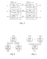
- FIG. 1 shows a general representation of a VOTRICS system
- FIG. 2 the cascading of VOTRICS nodes
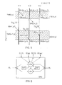
- FIG. 3 the convergence of VOTRICS nodes
- FIG. 4 a divergence of VOTRICS nodes
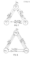
- FIG. 5 the temporal Uncertainty in the transmission of a triad of messages between two cascaded VOTRICS systems
- FIG. 6 shows the interaction of the voting functions in one computing unit
- FIG. 8 virtual duplication of the voting links by using redundancy in the time domain .
- a VOTRICS network consists of any network of one or more VOTRICS nodes, each of which forms an autonomous fault-tolerant subsystem.
- a VOTRICS node consists of three independent computer units of the same configuration - so-called Smallest Replaceable Units (SRU) - which are loosely meshed with one another by serial bidirectional voting links VL.
- SRU Smallest Replaceable Units
- Each SRU is connected to the environment through one or more serial input and output channels IC, OC.
- Fig. L shows the most general arrangement of such a system consisting of SRU (al) ... SRU (an), which work together in active redundancy and SRU (pl) ... SRU (pn) in passive redundancy (standby).
- a prerequisite for the successful application of active redundancy is an efficient voting mechanism, which allows the results and the behavior of the computers working in active redundancy to be compared continuously and under real-time conditions.
- the voting mechanism i.e. to be able to tolerate the error (error masking)
- at least 2N + 1 results determined independently of one another are necessary.
- active redundancy Simultaneous determination of the results, once per computer
- at least three computers are necessary to be able to tolerate an error.
- TMR Triple Modular Redundancy
- Special voting hardware is used in many of the fault-tolerant systems mentioned in the literature. If this voting hardware is carried out simply, it worsens the mean time between failures (MTBF) of the TMR system. The failure of the voting hardware results in a total failure. Solutions with redundant voting hardware are also known (see for example: AL Hopkins Jr., FTMP - A Highly Reliable Fault-Tolerant Multi- processor for Aircraft, Proc. Of the IEEE, Vol 66 No. lo. Pp l22l - l239, Oct l978 ). Although these provide a comparatively better reliability, they require considerable additional hardware expenditure.
- the voting function is therefore divided between the individual computer units (SRUs) of the system.
- SRUs computer units
- this can be done by software voters in everyone individual computing unit.
- the architecture described below allows any combination of SRU's in active and / or passive redundancy, so it can be flexibly adapted to the required reliability or availability.
- Lamport & PM Melliar-Smith Synchronizing Clocks in the Presence of Faults, Journal of the ACM, Vol 32 No l, pp. 52 - 78, Jan l985).
- Time measurements in VOTRICS are only carried out using a relative time base - only time differences are measured, ie the inevitable drift of the hardware timers cannot have any effect.
- process scheduling is not carried out in a fixed, periodic time schedule, but according to a simple, priority-controlled FIFO procedure. All actions take place on the basis of (stochastic) external and internal events. By eliminating the coupling of the scheduling to a system-wide time base, it is necessary to use suitable synchronization measures to coordinate the scheduling activities among the SRUs working in active redundancy.
- Both VOTRICS nodes and the computer units SRU within a node are networked with one another by serial point-to-point connections.
- An alternative to this would be computer couplings via redundant "broadcast buses".
- the point-to-point connections provide a simple method to limit the spread of errors, since only two units of SRU can be affected by a link error.
- Each VOTRICS node forms a fault-tolerant subsystem.
- An essential goal of this concept is the possibility of being able to build up a distributed computer network from several such subsystems. For this it is necessary to connect VOTRICS nodes with each other.
- the coupling of two VOTRICS nodes takes place through three point-to-point connections (paired connection of two neighboring SRUs). In this way, any network topology can be created by cascading and branching.
- the node TMR (n, x) (node x of level n) and the node TMR (n + l, y) (node y of level n + l) are via channels K1, K2 and K3 cascaded.
- the three computer units SRU (1, 2, 3) are completely intermeshed within each node.
- FIG. 3 shows the convergence in a VOTRICS arrangement.
- This type of message synchronization corresponds to the principle of event control, according to which all actions of application processes can only be triggered by messages.
- the CHILL application process is not interrupt-controlled; Interrupts are handled by the operating system and are only used to handle serial communication between SRUs.
- FIG. 5 shows the uncertainty in time during the transmission of a message triad between two cascaded VOTRICS systems.
- Communication between neighboring VOTRICS nodes takes place via 'message triads': three identical messages are exchanged between the three SRU pairs of two neighboring VOTRICS nodes via the three connecting lines. Due to the different processing times in the SRUs of the sending and receiving VOTRICS nodes and also due to possible differences in the transmission times (serial transmission method), the messages of a triad arrive with a time uncertainty in the receiver processes.
- the three computer units SRU (n, x, l) present in the node TMR (n, x) (from FIG. 2) send SRU (n, x, 2) and SRU (n, x, 3) on the channels Kl, K2, K3 the output messages OM (n, x, l), OM (n, x, 2) and OM (n, x, 3) from.
- the max. Output blur Uamax (n, x) is given in this case by the time interval between the output messages OM (n, x, l) and OM (n, x, 2).
- the transmission sharpness Utue (n, x - n + l, y) is TUe2 minus TUel in the present example.
- the receiver receives the same sequence of messages on every single input channel of a triad (no transmission errors). If several input channels are connected to each SRU (convergence, see FIG. 4), this no longer applies to the sum of the messages received from these channels.
- the synchronization algorithm used in VOTRICS to solve this problem is based on the principle of a distributed 'sequence voting' on the sequence of input messages passed on from the individual SRUs of a TMR system to the application processes, which will be described in a later section.
- timeout messages Since the clocks are not synchronized and the application processes run with considerable time blurring in the three computer units, the sequence of the timeout messages is not necessarily identical in all three units. However, the timeout messages generated by the operating system can be viewed as an additional input channel, and therefore identical timeout messages are sent to the application processes to all computer units.
- the voters can be used for a wide variety of tasks, the following basic functions are carried out by each voter: error detection, error masking and synchronization.
- sequence- Voting and input / output voting differentiated.
- each computer unit SRU there is an input / output voter IOV which forms a voting triad with its neighboring voters by means of voting links VL.
- This voter now has to vote on all incoming or outgoing message triads of a VOTRICS node.
- the source for incoming message triads are the input channels ICl ... ICn and the timeout handler TOH of the operating system.
- the outgoing messages which are processed by the AP application processor leave the VOTRICS node via the output channels OCl ... OCm after they have been recognized as correct by the input-output voter.
- the input message sequences generated by the input / output voters are different in each SRU, although the amount of messages in each sequence is the same. All input message triads that were accepted as correct during the input voting are therefore redirected to the sequence voter SV, where a uniform sequence of the messages is produced and then passed on to the application process.
- Voters have the task of recognizing error situations and masking them if possible, but cannot take system-wide measures such as Stop your own SRU, recovery etc.
- EMP 'Error Monitoring Process'
- each application process can start one or more independent time monitoring. After such a timeout has expired, the process receives a message from the operating system that it specified when the timeout was started.
- timeout expires in one SRU and not in the other two (or vice versa). Although this is not an error situation, it is not desirable to deal with such situations in the sequence voter (the sequence voter would be a lot more complex if the timeout message were handled specially).
- the timeout signals are therefore forwarded to the input / output voter, who then ensures that only complete timeout message triads are forwarded to the sequence voter triad.
- the input / output voting triad also votes on all signals that leave the VOTRICS node.
- the purpose of the output voting is to identify errors in the neighboring units, to mask the errors and to provide the output triad with a uniform identifier.
- the sequence of signals leaves the Votrics node in the same sequence as it was created by the application process.
- each concrete input / output vote is only carried out via three redundant objects (in most cases signal triads), the input / output votes must process the sequences of such triads correctly. This results in a few boundary conditions: -The triads of a logical channel (e.g. an input channel) must be output in the same order in which they arrived. Since a triplicated channel generates three identical signal sequences, a uniform sequence is defined in the signal triads. -The sequence in which signals are transmitted from different logical channels is arbitrary. - A faulty triad must not affect the processing of other triads in the same voter.
- Triads from different logical channels should therefore be processed and transmitted in parallel, while successive triads on a single logical channel must be transmitted sequentially.
- the triads can influence each other in different ways, namely through -Triad overlap on a single logical channel: If the time interval between the arrival of triads is smaller than the time blur within the three signals of the triad, it can happen, for example, that the signal arrives later on the "own" input channel of the voter than one or both Voting signals one subsequent triad (the incept signals which the neighboring voters receive and pass on). In the case of a "defective" triad, ie a triad with an incorrect or non-existent signal, much more complex situations can arise.
- Channel overlap The input / output voter has to process triads from several logical input channels (at least from a physical input channel and a timeout handler). The signals of such triads can arrive in any order.
- the input / output voter must therefore be able to process any combination of triad and channel overlap.
- the basic principle of the distributed voting used here is that each voter passes on the content of an input message received by him to his partners by sending 'voting messages'.
- An output of the voting result (e.g. in the case of IOV transfer to the sequence voter) takes place exclusively on the basis of a 2 out of 3 majority decision (commitment).
- This voting algorithm relates to a news triad.
- a voter can vote across multiple triads simultaneously to search for triad or channel overlap, however the sequence of commitments across each logical channel must match the input sequence of that logical channel.
- sequence voting will now be described.
- the task of the sequence voter triad is the coordinated forwarding of a uniform input message sequence to the application processes of each SRU.
- Each sequence voter receives the message sequences generated by the IOV and unites them in coordination with his neighbors to a resulting news sequence accepted by all three sequence voters.
- the correctly ordered signals which are identical in each computer unit (SRU), are then passed on to the application processes in order to synchronize their processes.
- the sequence voter like other voters, performs error masking. However, if a sequence voter detects an error, this always means a critical situation. It is very likely that the voter who sent the message is defective. If this is an error in your own SRU, this is subsequently stopped by the 'Error Monitoring Process'.
- voting links form the only connections between the SRUs of a VOTRICS system. In order to achieve maximum independence of the individual error behavior of the SRUs of a VOTRICS system, it must be prevented that neighboring SRUs can export or import errors via the voting links.
- the resulting arrangement of the voting links for the computer unit SRUk can be seen from FIG.
- the voter of this unit accordingly receives the above-mentioned voting messages from the input channel ICk and the voting links VLjk from the computer unit SRUj and VLik from the computer unit SRUi and from the additional virtual voting links VLjk ⁇ from the computer unit SRUj via SRUi and Vlik from the computer unit SRUi via SRUj.
- VMij VMik.
- VMij is forwarded from SRUj to SRUk (VMik), VMik from SRUk to SRUj (VMij ⁇ );
- Both SRUj and SRUk can independently determine by checking the conditions (VMij-VMij) or (VMik VMik ⁇ ) that SRUi is lying. In both cases, the condition is not met.
- Each SRU protects the voting messages it produces with an individual, unique signature.
- each SRU only knows its own coding algorithm.
- ENCODEi (VMix) is only known to SRUi.
- Each voting message is provided with its individual signature by the source SRU.
- no signature is applied.
- the destination SRU can use the decoding algorithm known to it and thus check whether the message has been damaged on the way through the neighboring SRU.
- SRUi produces VMij and VMik. Before sending to SRU j or SRUk, the signature is applied, specifically for VMij: “ENCODEi (VMij)" and for VMik: “ENCODEi (VMik)”. SRUj duplicates VMij and sends (without applying its own signature VMik to SRUk, but at the same time SRUj also performs the decoding functions for its own message (DECODEi (VMij)).
- DECODEi VMij
- SRUk receives VMik and VMik ⁇ and executes the decoding function DECODE: (VMik) and DECODE (VMik ⁇ ); SRUk also produces a VMij (but without its own signature) and sends it to SRUj where it is received, decrypted with DECODE (VMij ⁇ ) and compared with the decrypted VMij.
- the timing of the system in the event of a failed voting link is also improved in such a way that in this situation the input blur no longer enters into the commitment blur during voting.
Landscapes
- Engineering & Computer Science (AREA)
- Theoretical Computer Science (AREA)
- Quality & Reliability (AREA)
- Physics & Mathematics (AREA)
- General Engineering & Computer Science (AREA)
- General Physics & Mathematics (AREA)
- Hardware Redundancy (AREA)
- Image Analysis (AREA)
- Detection And Prevention Of Errors In Transmission (AREA)
Applications Claiming Priority (2)
| Application Number | Priority Date | Filing Date | Title |
|---|---|---|---|
| AT1286/86 | 1986-05-14 | ||
| AT128686 | 1986-05-14 |
Publications (3)
| Publication Number | Publication Date |
|---|---|
| EP0246218A2 true EP0246218A2 (fr) | 1987-11-19 |
| EP0246218A3 EP0246218A3 (en) | 1989-09-06 |
| EP0246218B1 EP0246218B1 (fr) | 1993-08-18 |
Family
ID=3510601
Family Applications (1)
| Application Number | Title | Priority Date | Filing Date |
|---|---|---|---|
| EP87890089A Expired - Lifetime EP0246218B1 (fr) | 1986-05-14 | 1987-05-07 | Système de traitement de données à tolérance de fautes |
Country Status (4)
| Country | Link |
|---|---|
| EP (1) | EP0246218B1 (fr) |
| AT (1) | ATE93332T1 (fr) |
| DE (1) | DE3787045D1 (fr) |
| ES (1) | ES2044975T3 (fr) |
Cited By (6)
| Publication number | Priority date | Publication date | Assignee | Title |
|---|---|---|---|---|
| US5754757A (en) * | 1992-11-06 | 1998-05-19 | The University Of Newcastle Upon Tyne | Efficient schemes for constructing reliable computing nodes in distributed systems |
| DE19742918A1 (de) * | 1997-09-29 | 1999-04-01 | Cit Alcatel | Verfahren zum Austausch von Datenpaketen innerhalb eines sicheren Mehrrechnersystems |
| DE19831720A1 (de) * | 1998-07-15 | 2000-01-20 | Alcatel Sa | Verfahren zur Ermittlung einer einheitlichen globalen Sicht vom Systemzustand eines verteilten Rechnernetzwerks |
| EP1148396A1 (fr) * | 2000-04-22 | 2001-10-24 | Siemens Schweiz AG | Surveillance d'un réseau de calculateurs |
| EP1205834A3 (fr) * | 2000-11-09 | 2004-02-11 | Alcatel | Méthode de mémorisation d'une clé de sécurité et système comportant plusieurs stations pour la mise en oeuvre du procédé |
| WO2013123543A1 (fr) * | 2012-02-22 | 2013-08-29 | Fts Computertechnik Gmbh | Procédé de détection d'erreurs dans un système de systèmes |
Families Citing this family (2)
| Publication number | Priority date | Publication date | Assignee | Title |
|---|---|---|---|---|
| DE19740136A1 (de) * | 1997-09-12 | 1999-03-18 | Alsthom Cge Alcatel | Verfahren zur Isolation eines defekten Rechners in einem fehlertoleranten Mehrrechnersystem |
| DE19745994A1 (de) * | 1997-10-20 | 1999-04-22 | Cit Alcatel | Verfahren zum Austausch von Daten zwischen Applikationsprozessen in einem sicheren Mehrrechnersystem |
Family Cites Families (1)
| Publication number | Priority date | Publication date | Assignee | Title |
|---|---|---|---|---|
| DE2939487A1 (de) * | 1979-09-28 | 1981-04-16 | Siemens AG, 1000 Berlin und 8000 München | Rechnerarchitektur auf der basis einer multi-mikrocomputerstruktur als fehlertolerantes system |
-
1987
- 1987-05-07 EP EP87890089A patent/EP0246218B1/fr not_active Expired - Lifetime
- 1987-05-07 AT AT87890089T patent/ATE93332T1/de not_active IP Right Cessation
- 1987-05-07 DE DE8787890089T patent/DE3787045D1/de not_active Expired - Lifetime
- 1987-05-07 ES ES87890089T patent/ES2044975T3/es not_active Expired - Lifetime
Cited By (10)
| Publication number | Priority date | Publication date | Assignee | Title |
|---|---|---|---|---|
| US5754757A (en) * | 1992-11-06 | 1998-05-19 | The University Of Newcastle Upon Tyne | Efficient schemes for constructing reliable computing nodes in distributed systems |
| DE19742918A1 (de) * | 1997-09-29 | 1999-04-01 | Cit Alcatel | Verfahren zum Austausch von Datenpaketen innerhalb eines sicheren Mehrrechnersystems |
| EP0905623A3 (fr) * | 1997-09-29 | 1999-07-28 | Alcatel | Méthode pour l'échange de packets de données dans un système sécurisé de multi-ordinateur |
| DE19831720A1 (de) * | 1998-07-15 | 2000-01-20 | Alcatel Sa | Verfahren zur Ermittlung einer einheitlichen globalen Sicht vom Systemzustand eines verteilten Rechnernetzwerks |
| US6574744B1 (en) | 1998-07-15 | 2003-06-03 | Alcatel | Method of determining a uniform global view of the system status of a distributed computer network |
| EP1148396A1 (fr) * | 2000-04-22 | 2001-10-24 | Siemens Schweiz AG | Surveillance d'un réseau de calculateurs |
| WO2001082010A1 (fr) * | 2000-04-22 | 2001-11-01 | Siemens Schweiz Ag | Systeme et procede de surveillance pour installations de traitement de donnees en reseau |
| EP1205834A3 (fr) * | 2000-11-09 | 2004-02-11 | Alcatel | Méthode de mémorisation d'une clé de sécurité et système comportant plusieurs stations pour la mise en oeuvre du procédé |
| WO2013123543A1 (fr) * | 2012-02-22 | 2013-08-29 | Fts Computertechnik Gmbh | Procédé de détection d'erreurs dans un système de systèmes |
| US9575859B2 (en) | 2012-02-22 | 2017-02-21 | Fts Computertechnik Gmbh | Method for fault recognition in a system of systems |
Also Published As
| Publication number | Publication date |
|---|---|
| ES2044975T3 (es) | 1994-01-16 |
| EP0246218B1 (fr) | 1993-08-18 |
| EP0246218A3 (en) | 1989-09-06 |
| DE3787045D1 (de) | 1993-09-23 |
| ATE93332T1 (de) | 1993-09-15 |
Similar Documents
| Publication | Publication Date | Title |
|---|---|---|
| DE3685609T2 (de) | Kommunikationsverfahren fuer multiprozessor. | |
| DE3750967T2 (de) | Steuerung von verteilten Taktimpulsen in einer verteilten Digital-Vermittlungsanlage. | |
| DE2908316C2 (de) | Modular aufgebaute Multiprozessor-Datenverarbeitungsanlage | |
| DE69604249T2 (de) | Fehlertolerantes verteiltes Steuerungssystem | |
| EP2857913B1 (fr) | Système d'automatisation redondant | |
| DE3328405C2 (fr) | ||
| DE2626838B2 (de) | Prüf-Schaltungsanordnung für eine Fernmeldeinstallation | |
| DE69223990T2 (de) | Auch gegen mehrfachfehler sicherer, fehlertoleranter taktgeber | |
| EP0897626A1 (fr) | Protocole destine a des applications critiques pour la securite | |
| EP0092719A1 (fr) | Disposition pour le couplage d'unités de traitement numérique | |
| EP0701346A2 (fr) | Procédé pour la transmission consistante de données | |
| EP0246218B1 (fr) | Système de traitement de données à tolérance de fautes | |
| DE2729362C2 (de) | Digitale Datenverarbeitungsanordnung, insbesondere für die Eisenbahnsicherungstechnik, mit in zwei Kanälen dieselben Informationen verarbeitenden Schaltwerken | |
| DE60104336T2 (de) | Fehlertolerante synchronisationseinrichtung für ein echtzeit-computernetzwerk | |
| EP0543825A1 (fr) | Installation pour la repartition des interruptions dans un systeme a plusieurs ordinateurs. | |
| EP0720337B1 (fr) | Méthode de communication de messages consistente et à haute fiabilité | |
| EP1283468B1 (fr) | Unité centrale pour un système d'automatisation redondant | |
| EP3273352B1 (fr) | Système informatisé | |
| EP1050814B1 (fr) | Système tolérant de fautes utilisant un algorithme byzantine | |
| DD153258A5 (de) | Sichere datenverarbeitungseinrichtung | |
| EP1484679B1 (fr) | Méthode et système pour garantir des temps de réponses maximaux pour systèmes complexes ou distribués , sécurisés ou non | |
| DE69025242T2 (de) | Kommunikationseinrichtung zur Überwachung der übertragenen Datenmenge | |
| EP1287435B1 (fr) | Dispositif et procede pour la synchronisation d'un systeme d'installations informatiques couplees | |
| EP0935198B1 (fr) | Méthode et système informatique de traitement de données sécurisée | |
| DE19619886C2 (de) | Steuer- und Datenübertragungsanlage mit teilweise redundantem Bussystem |
Legal Events
| Date | Code | Title | Description |
|---|---|---|---|
| PUAI | Public reference made under article 153(3) epc to a published international application that has entered the european phase |
Free format text: ORIGINAL CODE: 0009012 |
|
| AK | Designated contracting states |
Kind code of ref document: A2 Designated state(s): AT BE CH DE ES FR GB GR IT LI LU NL SE |
|
| PUAL | Search report despatched |
Free format text: ORIGINAL CODE: 0009013 |
|
| AK | Designated contracting states |
Kind code of ref document: A3 Designated state(s): AT BE CH DE ES FR GB GR IT LI LU NL SE |
|
| 17P | Request for examination filed |
Effective date: 19900207 |
|
| 17Q | First examination report despatched |
Effective date: 19920403 |
|
| GRAA | (expected) grant |
Free format text: ORIGINAL CODE: 0009210 |
|
| AK | Designated contracting states |
Kind code of ref document: B1 Designated state(s): AT BE CH DE ES FR GB GR IT LI LU NL SE |
|
| PG25 | Lapsed in a contracting state [announced via postgrant information from national office to epo] |
Ref country code: GR Free format text: LAPSE BECAUSE OF FAILURE TO SUBMIT A TRANSLATION OF THE DESCRIPTION OR TO PAY THE FEE WITHIN THE PRESCRIBED TIME-LIMIT Effective date: 19930818 |
|
| REF | Corresponds to: |
Ref document number: 93332 Country of ref document: AT Date of ref document: 19930915 Kind code of ref document: T |
|
| ITF | It: translation for a ep patent filed | ||
| REF | Corresponds to: |
Ref document number: 3787045 Country of ref document: DE Date of ref document: 19930923 |
|
| GBT | Gb: translation of ep patent filed (gb section 77(6)(a)/1977) |
Effective date: 19931014 |
|
| ET | Fr: translation filed | ||
| REG | Reference to a national code |
Ref country code: ES Ref legal event code: FG2A Ref document number: 2044975 Country of ref document: ES Kind code of ref document: T3 |
|
| PG25 | Lapsed in a contracting state [announced via postgrant information from national office to epo] |
Ref country code: LU Free format text: LAPSE BECAUSE OF NON-PAYMENT OF DUE FEES Effective date: 19940531 |
|
| PLBE | No opposition filed within time limit |
Free format text: ORIGINAL CODE: 0009261 |
|
| STAA | Information on the status of an ep patent application or granted ep patent |
Free format text: STATUS: NO OPPOSITION FILED WITHIN TIME LIMIT |
|
| 26N | No opposition filed | ||
| EAL | Se: european patent in force in sweden |
Ref document number: 87890089.3 |
|
| PGFP | Annual fee paid to national office [announced via postgrant information from national office to epo] |
Ref country code: BE Payment date: 20010514 Year of fee payment: 15 |
|
| REG | Reference to a national code |
Ref country code: GB Ref legal event code: IF02 |
|
| PG25 | Lapsed in a contracting state [announced via postgrant information from national office to epo] |
Ref country code: BE Free format text: LAPSE BECAUSE OF NON-PAYMENT OF DUE FEES Effective date: 20020531 |
|
| PGFP | Annual fee paid to national office [announced via postgrant information from national office to epo] |
Ref country code: SE Payment date: 20060512 Year of fee payment: 20 |
|
| PGFP | Annual fee paid to national office [announced via postgrant information from national office to epo] |
Ref country code: NL Payment date: 20060515 Year of fee payment: 20 Ref country code: CH Payment date: 20060515 Year of fee payment: 20 Ref country code: AT Payment date: 20060515 Year of fee payment: 20 |
|
| PGFP | Annual fee paid to national office [announced via postgrant information from national office to epo] |
Ref country code: FR Payment date: 20060519 Year of fee payment: 20 Ref country code: DE Payment date: 20060519 Year of fee payment: 20 |
|
| PGFP | Annual fee paid to national office [announced via postgrant information from national office to epo] |
Ref country code: GB Payment date: 20060522 Year of fee payment: 20 |
|
| PGFP | Annual fee paid to national office [announced via postgrant information from national office to epo] |
Ref country code: ES Payment date: 20060530 Year of fee payment: 20 |
|
| PGFP | Annual fee paid to national office [announced via postgrant information from national office to epo] |
Ref country code: IT Payment date: 20060531 Year of fee payment: 20 |
|
| PG25 | Lapsed in a contracting state [announced via postgrant information from national office to epo] |
Ref country code: NL Free format text: LAPSE BECAUSE OF EXPIRATION OF PROTECTION Effective date: 20070507 |
|
| PG25 | Lapsed in a contracting state [announced via postgrant information from national office to epo] |
Ref country code: ES Free format text: LAPSE BECAUSE OF EXPIRATION OF PROTECTION Effective date: 20070508 |
|
| REG | Reference to a national code |
Ref country code: GB Ref legal event code: PE20 |
|
| REG | Reference to a national code |
Ref country code: CH Ref legal event code: PL |
|
| NLV7 | Nl: ceased due to reaching the maximum lifetime of a patent |
Effective date: 20070507 |
|
| EUG | Se: european patent has lapsed | ||
| REG | Reference to a national code |
Ref country code: ES Ref legal event code: FD2A Effective date: 20070508 |
|
| PG25 | Lapsed in a contracting state [announced via postgrant information from national office to epo] |
Ref country code: GB Free format text: LAPSE BECAUSE OF EXPIRATION OF PROTECTION Effective date: 20070506 |