EP0246210A2 - Device in strap tensioners - Google Patents
Device in strap tensioners Download PDFInfo
- Publication number
- EP0246210A2 EP0246210A2 EP87850134A EP87850134A EP0246210A2 EP 0246210 A2 EP0246210 A2 EP 0246210A2 EP 87850134 A EP87850134 A EP 87850134A EP 87850134 A EP87850134 A EP 87850134A EP 0246210 A2 EP0246210 A2 EP 0246210A2
- Authority
- EP
- European Patent Office
- Prior art keywords
- shaft
- strap
- holder member
- halves
- circle sector
- Prior art date
- Legal status (The legal status is an assumption and is not a legal conclusion. Google has not performed a legal analysis and makes no representation as to the accuracy of the status listed.)
- Withdrawn
Links
Images
Classifications
-
- B—PERFORMING OPERATIONS; TRANSPORTING
- B60—VEHICLES IN GENERAL
- B60P—VEHICLES ADAPTED FOR LOAD TRANSPORTATION OR TO TRANSPORT, TO CARRY, OR TO COMPRISE SPECIAL LOADS OR OBJECTS
- B60P7/00—Securing or covering of load on vehicles
- B60P7/06—Securing of load
- B60P7/08—Securing to the vehicle floor or sides
- B60P7/0823—Straps; Tighteners
- B60P7/083—Tensioning by repetetive movement of an actuating member
-
- A—HUMAN NECESSITIES
- A44—HABERDASHERY; JEWELLERY
- A44B—BUTTONS, PINS, BUCKLES, SLIDE FASTENERS, OR THE LIKE
- A44B11/00—Buckles; Similar fasteners for interconnecting straps or the like, e.g. for safety belts
- A44B11/02—Buckles; Similar fasteners for interconnecting straps or the like, e.g. for safety belts frictionally engaging surface of straps
- A44B11/06—Buckles; Similar fasteners for interconnecting straps or the like, e.g. for safety belts frictionally engaging surface of straps with clamping devices
- A44B11/12—Buckles; Similar fasteners for interconnecting straps or the like, e.g. for safety belts frictionally engaging surface of straps with clamping devices turnable clamp
- A44B11/125—Buckles; Similar fasteners for interconnecting straps or the like, e.g. for safety belts frictionally engaging surface of straps with clamping devices turnable clamp with strap tightening means
Definitions
- the present invention relates to a device in strap tensioners of the type recited in the preamble to the accompanying claim 1.
- one strap is firmly retained in a holder member, which is rotatably mounted about a shaft, the other end of the strap being reeled up on the shaft for tensioning the strap about a load, for example.
- An operating member is mounted for rotation about the shaft and is also adapted for rotating the latter with the aid of a pawl mechanism engaging in ratchet wheels fixedly mounted on the shaft.
- the shaft is restrained from rotating in the opposite direction by a stop pawl mechanism disposed on the holder member.
- the main object of the invention is to improve and simplify the shaft structure in this type of strap tensioner, the object being achieved by the apparatus in accordance with the invention being given the characterizing features disclosed in the accompanying claims.
- the strap tensioner illustrated in Figure 1 includes a strap holder member 10 and an operating member 12, both mounted for rotation on a common shaft 14.
- the member 10 includes two cheek plates 16,in mutually spaced, parallel relationship, these plates being united by a bottom plate 18.
- a shaft 20 is also fixed between the plates 16, to this shaft there being attached an end of the strap 22, which is to be tensioned or stretched.
- the cheek plates 16 are also provided with openings, not given denotations, through the shaft 14 passes with clearance such as to enable the holder member 10 to rotate about the shaft.
- the operating member 12 includes two cheek plates 42, which are united by a handle 44 riveted thereto at the end of the member remote from the shaft 14.
- a shaft 46 also keeps the cheek plates together.
- a pawl plate 50 is accommodated between the cheek plates 42, and in slots 48 in the plates. With the aid of a spring 52 engaging the plate 50 at its centre and in holes in one cheek plate 42, the pawl plate 50 is biased towards the ratchet wheels 30, projecting tongues 54 on the pawl plate 50 engaging against teeth on the ratchet wheels.
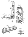
- the shaft 14 comprises two circle sector - shaped halves 36, 38 acconmodated in complemental slots in the ratchet wheels 30 at a mutual spacing corresponding to the desired width of the slot (see Figure 2).
- the shaft 14 is axially restrained by dowel pins 40 or the like disposed exterior to the operating member 12.
- the two halves 36, 38 of the shaft 14 are fabricated from elongate plates, which are curved and folded to the desired configuration illustrated in the Figures. Each plate is accordingly folded into a circle sector - shaped hollow section, preferably a semi-circular section 36, 38.
- the halves are thus given greater strength, to enable them to withstand the large forces exercised by the strap on the shaft, since the longitudinal edge portions 36a, 36b and 38a 38b have been folded inwards at substantially 90° to the flat portion of the-semi-circular section and into engagement with the inner circumference of the circular arc.
- the tensioner By fabricating the shaft 14 in two hollow sections 36, 38, and preferably from folded plates, the tensioner will be substantially lighter and cheaper to manufacture than conventional tensioners having a solid shaft with a machined slot for the strap.
- the unique shaft structure in accordance with the invention does not cause any weakness in the shaft, and it has practically the same strength, material strength, stableness of shape etc, provided by a solid shaft.
Landscapes
- Engineering & Computer Science (AREA)
- Transportation (AREA)
- Mechanical Engineering (AREA)
- Package Frames And Binding Bands (AREA)
- Devices For Conveying Motion By Means Of Endless Flexible Members (AREA)
- Impression-Transfer Materials And Handling Thereof (AREA)
Abstract
Description
- The present invention relates to a device in strap tensioners of the type recited in the preamble to the accompanying claim 1.
- In such tensioners, one strap is firmly retained in a holder member, which is rotatably mounted about a shaft, the other end of the strap being reeled up on the shaft for tensioning the strap about a load, for example. An operating member is mounted for rotation about the shaft and is also adapted for rotating the latter with the aid of a pawl mechanism engaging in ratchet wheels fixedly mounted on the shaft. The shaft is restrained from rotating in the opposite direction by a stop pawl mechanism disposed on the holder member.
- The main object of the invention is to improve and simplify the shaft structure in this type of strap tensioner, the object being achieved by the apparatus in accordance with the invention being given the characterizing features disclosed in the accompanying claims.
- The invention will now be described in detail in connection with the accompanying drawing illustraing a preferred embodiment of a strap tensioner executed in accordance with the invention, and on which
- Figure 1 is a section through a strap tensioner,
- Figure 2 is a perspective view of the operating member and shaft,
- Figure 3 is a perspective view of the shaft, and
- Figure 4 is a section through the shaft.
- The strap tensioner illustrated in Figure 1 includes a
strap holder member 10 and anoperating member 12, both mounted for rotation on acommon shaft 14. Themember 10 includes twocheek plates 16,in mutually spaced, parallel relationship, these plates being united by abottom plate 18. Ashaft 20 is also fixed between theplates 16, to this shaft there being attached an end of thestrap 22, which is to be tensioned or stretched. There areslots 24 in theplates 16 for accommodating a stop pawl plate 26, which is biased by aspring 28 towards theshaft 14 such as to cause the stop pawl plate 26 to engage the teeth ofratchet wheel 30, described later, these wheels being mounted on theshaft 14. Thecheek plates 16 are also provided with openings, not given denotations, through theshaft 14 passes with clearance such as to enable theholder member 10 to rotate about the shaft. - The
operating member 12 includes twocheek plates 42, which are united by ahandle 44 riveted thereto at the end of the member remote from theshaft 14. Ashaft 46 also keeps the cheek plates together. Apawl plate 50 is accommodated between thecheek plates 42, and inslots 48 in the plates. With the aid of aspring 52 engaging theplate 50 at its centre and in holes in onecheek plate 42, thepawl plate 50 is biased towards theratchet wheels 30, projectingtongues 54 on thepawl plate 50 engaging against teeth on the ratchet wheels. When theoperating member 12 is rotated anti-clockwise in relation to theholder member 10 andshaft 14, thepawl plate 50 will glide over the sloping flanks of theratchet wheel 30 teeth against the bias of thespring 52, during which movement the shaft is motionless. Clockwise movement of theoperating member 12 causes thelocking plate 50 to engage the teeth onratchet wheels 30, giving them, and consequently theshaft 14, rotational movement relative theholder member 10 so that thestrap end portion 34 with its end inserted in theshaft slot 32 is tensioned. During this movement the stop pawl plate 26 in theholder member 10 will glide over the ratchet wheel teeth, and when the movement is terminated, this plate will prevent movement of the shaft in the opposite direction caused by tension in the strap. - The
shaft 14 comprises two circle sector -shaped halves ratchet wheels 30 at a mutual spacing corresponding to the desired width of the slot (see Figure 2). Theshaft 14 is axially restrained bydowel pins 40 or the like disposed exterior to theoperating member 12. - In accordance with the invention, the two
halves shaft 14 are fabricated from elongate plates, which are curved and folded to the desired configuration illustrated in the Figures. Each plate is accordingly folded into a circle sector - shaped hollow section, preferably asemi-circular section longitudinal edge portions 38a 38b have been folded inwards at substantially 90° to the flat portion of the-semi-circular section and into engagement with the inner circumference of the circular arc. - By fabricating the
shaft 14 in twohollow sections - It will be clearly understood that the illustrated and described embodiment is merely one example of how to realise the invention, and it may be altered and modified within the scope of the following claims.
Claims (5)
Applications Claiming Priority (2)
| Application Number | Priority Date | Filing Date | Title |
|---|---|---|---|
| SE8602179 | 1986-05-13 | ||
| SE8602179A SE8602179D0 (en) | 1986-05-13 | 1986-05-13 | DEVICE FOR TAPE DRAWERS |
Publications (2)
| Publication Number | Publication Date |
|---|---|
| EP0246210A2 true EP0246210A2 (en) | 1987-11-19 |
| EP0246210A3 EP0246210A3 (en) | 1988-01-07 |
Family
ID=20364516
Family Applications (1)
| Application Number | Title | Priority Date | Filing Date |
|---|---|---|---|
| EP87850134A Withdrawn EP0246210A3 (en) | 1986-05-13 | 1987-04-23 | Device in strap tensioners |
Country Status (5)
| Country | Link |
|---|---|
| EP (1) | EP0246210A3 (en) |
| DK (1) | DK239187A (en) |
| FI (1) | FI82222C (en) |
| NO (1) | NO162267C (en) |
| SE (1) | SE8602179D0 (en) |
Cited By (8)
| Publication number | Priority date | Publication date | Assignee | Title |
|---|---|---|---|---|
| US4913608A (en) * | 1989-03-06 | 1990-04-03 | Royball Kenneth O | Strap tightening device |
| EP0399726A3 (en) * | 1989-05-22 | 1991-07-24 | Elephant Chain Block Company Limited | Load tying-up apparatus |
| US5282706A (en) * | 1992-09-24 | 1994-02-01 | Indiana Mills & Manufacturing, Inc. | Retractable tie-down assembly |
| US5549429A (en) * | 1994-04-12 | 1996-08-27 | Sergent; Delores A. | Ratchet-operating tool for strap-tightening mechanism |
| EP1062886A1 (en) * | 1999-05-21 | 2000-12-27 | Han-Ching Huang | Buckle device |
| US6665910B2 (en) * | 2002-03-25 | 2003-12-23 | Han-Ching Huang | Manual stretcher |
| WO2006001714A1 (en) * | 2004-06-25 | 2006-01-05 | Greyson Manufacturing Limited | A tensioning apparatus |
| USD729026S1 (en) | 2011-08-30 | 2015-05-12 | Master Lock Company Llc | Ratchet lock |
Families Citing this family (1)
| Publication number | Priority date | Publication date | Assignee | Title |
|---|---|---|---|---|
| USD675498S1 (en) | 2010-06-18 | 2013-02-05 | Master Lock Company Llc | Ratchet |
Family Cites Families (2)
| Publication number | Priority date | Publication date | Assignee | Title |
|---|---|---|---|---|
| EP0050467A1 (en) * | 1980-10-17 | 1982-04-28 | Raymond Richmond | Tensioning apparatus |
| DE3203750C2 (en) * | 1982-02-04 | 1986-07-24 | Edith 6901 Dossenheim Rutzki | Turnbuckle for belt straps |
-
1986
- 1986-05-13 SE SE8602179A patent/SE8602179D0/en unknown
-
1987
- 1987-04-23 EP EP87850134A patent/EP0246210A3/en not_active Withdrawn
- 1987-04-29 FI FI871903A patent/FI82222C/en not_active IP Right Cessation
- 1987-05-12 NO NO871963A patent/NO162267C/en unknown
- 1987-05-12 DK DK239187A patent/DK239187A/en not_active Application Discontinuation
Cited By (8)
| Publication number | Priority date | Publication date | Assignee | Title |
|---|---|---|---|---|
| US4913608A (en) * | 1989-03-06 | 1990-04-03 | Royball Kenneth O | Strap tightening device |
| EP0399726A3 (en) * | 1989-05-22 | 1991-07-24 | Elephant Chain Block Company Limited | Load tying-up apparatus |
| US5282706A (en) * | 1992-09-24 | 1994-02-01 | Indiana Mills & Manufacturing, Inc. | Retractable tie-down assembly |
| US5549429A (en) * | 1994-04-12 | 1996-08-27 | Sergent; Delores A. | Ratchet-operating tool for strap-tightening mechanism |
| EP1062886A1 (en) * | 1999-05-21 | 2000-12-27 | Han-Ching Huang | Buckle device |
| US6665910B2 (en) * | 2002-03-25 | 2003-12-23 | Han-Ching Huang | Manual stretcher |
| WO2006001714A1 (en) * | 2004-06-25 | 2006-01-05 | Greyson Manufacturing Limited | A tensioning apparatus |
| USD729026S1 (en) | 2011-08-30 | 2015-05-12 | Master Lock Company Llc | Ratchet lock |
Also Published As
| Publication number | Publication date |
|---|---|
| NO871963L (en) | 1987-11-16 |
| DK239187A (en) | 1987-11-14 |
| SE8602179D0 (en) | 1986-05-13 |
| FI82222C (en) | 1991-02-11 |
| FI871903L (en) | 1987-11-14 |
| DK239187D0 (en) | 1987-05-12 |
| NO162267C (en) | 1989-12-06 |
| FI871903A0 (en) | 1987-04-29 |
| NO162267B (en) | 1989-08-28 |
| FI82222B (en) | 1990-10-31 |
| NO871963D0 (en) | 1987-05-12 |
| EP0246210A3 (en) | 1988-01-07 |
Similar Documents
| Publication | Publication Date | Title |
|---|---|---|
| US20220203881A1 (en) | Ratchet tie down | |
| US4154427A (en) | Ratchet device for belts or ropes | |
| US5542798A (en) | Restraining and tensioning apparatus for a cargo tie-down belt | |
| US6609275B1 (en) | Strap tightener with an auto-pulling device | |
| US5103536A (en) | Tensioning apparatus for a lashing strap | |
| US6390562B1 (en) | Locking clip | |
| EP0246210A2 (en) | Device in strap tensioners | |
| EP3747697B1 (en) | Manual belt-winding safety tensioning device for automobile | |
| EP2356058B1 (en) | A spindle for a winch | |
| SE450937B (en) | BANDSPENNARE | |
| US6247208B1 (en) | Method and apparatus for tightening a belt, strap, or the like | |
| JPH067470A (en) | Safety device | |
| US4912813A (en) | Belt connection mechanism | |
| US3261062A (en) | Clamp assembly for hose, pipe and other articles | |
| JPS60155377A (en) | Tension device for long objects such as chains and belts | |
| CA3127691A1 (en) | Drive attachment for a ratchet-type load binder to enable selective driving thereof with a handheld power tool | |
| JPS5836565A (en) | Belt clamping apparatus of safety belt of automobile | |
| JPH052783Y2 (en) | ||
| JP2007511406A (en) | Seat belt retracting mechanism | |
| US4350063A (en) | Adjustable wrench | |
| US6539590B2 (en) | Seat belt tightner | |
| US4753427A (en) | Clamp with fast-acting, one-hand adjustment | |
| US4675949A (en) | Axially actuated hose clamp | |
| US4040602A (en) | Tensioning anchor | |
| US6530127B2 (en) | Restraint device with release mechanism |
Legal Events
| Date | Code | Title | Description |
|---|---|---|---|
| PUAI | Public reference made under article 153(3) epc to a published international application that has entered the european phase |
Free format text: ORIGINAL CODE: 0009012 |
|
| AK | Designated contracting states |
Kind code of ref document: A2 Designated state(s): DE FR GB SE |
|
| PUAL | Search report despatched |
Free format text: ORIGINAL CODE: 0009013 |
|
| AK | Designated contracting states |
Kind code of ref document: A3 Designated state(s): DE FR GB SE |
|
| 17P | Request for examination filed |
Effective date: 19880702 |
|
| 17Q | First examination report despatched |
Effective date: 19891228 |
|
| STAA | Information on the status of an ep patent application or granted ep patent |
Free format text: STATUS: THE APPLICATION IS DEEMED TO BE WITHDRAWN |
|
| 18D | Application deemed to be withdrawn |
Effective date: 19911001 |
|
| RIN1 | Information on inventor provided before grant (corrected) |
Inventor name: ERIKSSON, YNGVE |