EP0246110B1 - Valve for controlling the flow of liquid through a tube - Google Patents
Valve for controlling the flow of liquid through a tube Download PDFInfo
- Publication number
- EP0246110B1 EP0246110B1 EP19870304336 EP87304336A EP0246110B1 EP 0246110 B1 EP0246110 B1 EP 0246110B1 EP 19870304336 EP19870304336 EP 19870304336 EP 87304336 A EP87304336 A EP 87304336A EP 0246110 B1 EP0246110 B1 EP 0246110B1
- Authority
- EP
- European Patent Office
- Prior art keywords
- flow
- male
- valve
- female
- tube
- Prior art date
- Legal status (The legal status is an assumption and is not a legal conclusion. Google has not performed a legal analysis and makes no representation as to the accuracy of the status listed.)
- Expired
Links
Images

Classifications
-
- A—HUMAN NECESSITIES
- A61—MEDICAL OR VETERINARY SCIENCE; HYGIENE
- A61M—DEVICES FOR INTRODUCING MEDIA INTO, OR ONTO, THE BODY; DEVICES FOR TRANSDUCING BODY MEDIA OR FOR TAKING MEDIA FROM THE BODY; DEVICES FOR PRODUCING OR ENDING SLEEP OR STUPOR
- A61M39/00—Tubes, tube connectors, tube couplings, valves, access sites or the like, specially adapted for medical use
- A61M39/22—Valves or arrangement of valves
- A61M39/28—Clamping means for squeezing flexible tubes, e.g. roller clamps
- A61M39/286—Wedge clamps, e.g. roller clamps with inclined guides
Definitions
- This invention relates to valves which can be used to control the flow of fluid, i.e. liquid or gas, through a tube.
- Such control is required, for example, generally in the irrigation of a wound caused by injury or operation, and specifically in continuous ambulatory peritoneal dialysis (CAPD). It is conventional to control the irrigation flow in-line, by breaking the tube, and inserting a stopcock, or by applying a clamp to the tube (whose walls are of a deformable material).
- CAPD continuous ambulatory peritoneal dialysis
- CAPD and its requirements are described in WO-A-8301572.
- each patient has four cycles of treatment per day; in each cycle, an on/off valve has to be used four times. There are thus 16 switching actions per day.
- Three primary requirements of a CAPD patient for any online flow valve are (1) easy and simple operation, because a large proportion of patients are elderly or invalid; (2) robust construction which can stand up to a minimum of 1 year's safe usage, i.e. at least 5800 manipulations; and (3) small physical size, without sharp edges or corners, because the valve is part of the fluid transfer system which is permanently attached to the body of the patient.
- an online stopcock can be used to control liquid flow, but wears badly, depending on the material from which its 3-4 parts are contructed and the nature of the liquid (the material and the liquid are directly in contact, and the material is subject to contamination and corrosion). Such stopcocks tend to leak. Their action is undefined.
- roller clamps are known, in which a roller can be moved along a guide within a housing, from a flow-constricting position to a non-constricting position at opposite ends of the housing.
- Such roller clamps can wear well and exhibit good performance even in long-term operation, subject to the nature of the material from which they are constructed. However, their action is poorly defined, intermediate positions and thus the effect of the roller on fluid flow being unrepeatable, and the irregular shape of such clamps limits their clinical acceptability.
- Such valves are used in the Travenol Ambu-flex (registered Trade Mark) CAPD system.
- US-A-3550861 discloses a hose nozzle including a valve adapted to control the flow of liquid through a flexible tube, the valve comprising mutually-engaging essentially cylindrical male and female members, in which the male member has three apertures in its side-wall, and in which the internal diameter of the female member varies gradually from relatively narrow to relatively broad; and three balls, acting as a flow-constricting member, which are constrained to pass inwardly through the apertures when in contact with the relatively narrow internal diameter of the female member.
- the valve in an on-line valve of the general type described immediately above (although there will usually be only a single flow-constricting member and corresponding aperture), the valve includes positive location means, comprising a groove in the relatively narrow internal diameter portion of the female mamber for the flow-constricting member at maximum flow constriction (zero flow).
- the male and female members engage frictionally, and flow control (non-specific) is caused by push-pull operation.
- the male and female members have mutually-engaging screw threads.
- the second embodiment of the invention allows fully-controllable, positive and accurate flow control.
- a calibration dial may be provided.
- the female member is indicated as 1, the male member as 2 and the flow-constricting member as 3.
- Figs. 2A and 2B show mutually-engaging screw threads 4 on the members 1 and 2.
- the members 1 and 2 can be displaced axially with respect to each other.
- the drawings also show flexible tubing 6 which sits within the axial channel within the male member.
- the tubing 6 is respectively constricted and unconstricted in each of the two pairs of drawings.
- the flow-constricting member 3 is in contact with a relatively narrow internal diameter of the female member.
- a groove 5 provides means for positive location of the member 3 at zero flow.
- the member 3 is in contact with a relatively broad internal diameter.
- the male and female members may be constructed of, for example, the same or different plastics materials, or of glass or metal.
- the flow-constricting member may be spherical (as illustrated in the drawings), e.g. a steel ball.
- the dimensions of the male and female members and the flow-constricting member can easily be defined so that the flow-constricting member is retained by the two members, at least when they are mutually-engaging.
- the female member includes a section of varying internal diameter, between the limits of the relatively narrow and relatively broad internal diameters.
- the section of variation allows liquid flow through the tubing to be controlled very easily, between maximum and nil rates.
- Valves of the invention are simple to construct and use. On/off switching can be rapid. They do not suffer from the other disadvantages associated with the use of clamps. They can allow continuous variation of flow rates. They can be maintained in position on tubing as long as necessary, or moved along the tube when there is maximum flow. They can be operated manually or automatically (hydraulically, pneumatically or electrically).
- Valves of the invention can be used in the medical field, generally for blood and intravenous administration systems and also, for example, for haemodialysis and peritoneal dialysis. In industry, they can be used for various chemicals, and also in the domestic field for food, drink, oil and gas. Generally and also in the scientific field, they are suitable as general purpose/continuously-variable online flow switches/controllers. The only limitation on their performance lies in the nature of the flexible tubing material.
Description
- This invention relates to valves which can be used to control the flow of fluid, i.e. liquid or gas, through a tube.
- Such control is required, for example, generally in the irrigation of a wound caused by injury or operation, and specifically in continuous ambulatory peritoneal dialysis (CAPD). It is conventional to control the irrigation flow in-line, by breaking the tube, and inserting a stopcock, or by applying a clamp to the tube (whose walls are of a deformable material).
- CAPD and its requirements are described in WO-A-8301572. In general terms, each patient has four cycles of treatment per day; in each cycle, an on/off valve has to be used four times. There are thus 16 switching actions per day. Three primary requirements of a CAPD patient for any online flow valve are (1) easy and simple operation, because a large proportion of patients are elderly or invalid; (2) robust construction which can stand up to a minimum of 1 year's safe usage, i.e. at least 5800 manipulations; and (3) small physical size, without sharp edges or corners, because the valve is part of the fluid transfer system which is permanently attached to the body of the patient.
- For example, an online stopcock can be used to control liquid flow, but wears badly, depending on the material from which its 3-4 parts are contructed and the nature of the liquid (the material and the liquid are directly in contact, and the material is subject to contamination and corrosion). Such stopcocks tend to leak. Their action is undefined.
- Online one-piece spring clamps are known, having a number of settings by which fluid flow through the tube can be controlled. Their short-term performance is acceptable, but long-term performance is poor owing to the ageing of the material. Such clamps are often of irregular shape, with edges which limit their clinical acceptability.
- Other clamps are known, in which a roller can be moved along a guide within a housing, from a flow-constricting position to a non-constricting position at opposite ends of the housing. Such roller clamps can wear well and exhibit good performance even in long-term operation, subject to the nature of the material from which they are constructed. However, their action is poorly defined, intermediate positions and thus the effect of the roller on fluid flow being unrepeatable, and the irregular shape of such clamps limits their clinical acceptability. Such valves are used in the Travenol Ambu-flex (registered Trade Mark) CAPD system.
- US-A-3550861 discloses a hose nozzle including a valve adapted to control the flow of liquid through a flexible tube, the valve comprising mutually-engaging essentially cylindrical male and female members, in which the male member has three apertures in its side-wall, and in which the internal diameter of the female member varies gradually from relatively narrow to relatively broad; and three balls, acting as a flow-constricting member, which are constrained to pass inwardly through the apertures when in contact with the relatively narrow internal diameter of the female member.
- According to the present invention, in an on-line valve of the general type described immediately above (although there will usually be only a single flow-constricting member and corresponding aperture), the valve includes positive location means, comprising a groove in the relatively narrow internal diameter portion of the female mamber for the flow-constricting member at maximum flow constriction (zero flow).
- In one embodiment of the invention, the male and female members engage frictionally, and flow control (non-specific) is caused by push-pull operation.
- In a second embodiment of the invention, the male and female members have mutually-engaging screw threads. By turning the male and female members relative to one another, the second embodiment of the invention allows fully-controllable, positive and accurate flow control. For this purpose, a calibration dial may be provided.
- The invention will now be described by way of example only with reference to the accompanying drawings, in which:
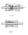
- Figures 1A and 1B are cross-sections along an axial plane of the same (first) embodiment of the invention, respectively showing the flow-constricting member in closed and open positions; and
- Figures 2A and 2B are views analogous to those of Figs. 1A and 1B, respectively, but of the second embodiment of the invention.
- In the drawings, the female member is indicated as 1, the male member as 2 and the flow-constricting member as 3. Further, Figs. 2A and 2B show mutually-
engaging screw threads 4 on themembers members - The drawings also show
flexible tubing 6 which sits within the axial channel within the male member. Thetubing 6 is respectively constricted and unconstricted in each of the two pairs of drawings. In the former case, (Figs. 1A and 2A), the flow-constrictingmember 3 is in contact with a relatively narrow internal diameter of the female member. A groove 5 provides means for positive location of themember 3 at zero flow. In the latter case, themember 3 is in contact with a relatively broad internal diameter. - The male and female members may be constructed of, for example, the same or different plastics materials, or of glass or metal. The flow-constricting member may be spherical (as illustrated in the drawings), e.g. a steel ball. The dimensions of the male and female members and the flow-constricting member can easily be defined so that the flow-constricting member is retained by the two members, at least when they are mutually-engaging.
- As shown in the drawings, the female member includes a section of varying internal diameter, between the limits of the relatively narrow and relatively broad internal diameters. The section of variation allows liquid flow through the tubing to be controlled very easily, between maximum and nil rates.
- Valves of the invention are simple to construct and use. On/off switching can be rapid. They do not suffer from the other disadvantages associated with the use of clamps. They can allow continuous variation of flow rates. They can be maintained in position on tubing as long as necessary, or moved along the tube when there is maximum flow. They can be operated manually or automatically (hydraulically, pneumatically or electrically).
- There is no fluid/valve contact, in a valve of the invention. There are no wearable or ageing moving parts. The design is compact, without sharp edges or breakable parts.
- Valves of the invention can be used in the medical field, generally for blood and intravenous administration systems and also, for example, for haemodialysis and peritoneal dialysis. In industry, they can be used for various chemicals, and also in the domestic field for food, drink, oil and gas. Generally and also in the scientific field, they are suitable as general purpose/continuously-variable online flow switches/controllers. The only limitation on their performance lies in the nature of the flexible tubing material.
Claims (9)
- An on-line valve for controlling the flow of a fluid through a flexible tube (6), comprising:
mutually-engaging essentially cylindrical male and female members (2,1), in which the male member (2) has an aperture in its side-wall, and in which the internal diameter of the female member (1) varies gradually from relatively narrow to relatively broad; and
a flow-constricting member (3) which is constrained to pass inwardly through the aperture when in contact with the relatively narrow internal diameter of the female member (2),
wherein, when the male and female members are engaged, they are axially moveable relative to each other, and define a bore in which the tube (6) can be located such that the flow-constricting member (3) is in contact with the tube (6);
characterised by positive location means, comprising a groove (5) in the relatively narrow internal diameter portion of the female member (1) for the flow-constricting member (3) at maximum flow constriction (zero flow). - A valve according to claim 1, in which the male member (2) is a frictional fit within the female member (1), such that flow control is achieved by push-pull operation.
- A valve according to claim 1, in which the male and female members (2,1) have mutually-engaging screw threads, which allows continuous variation in flow control.
- A valve according to claim 3, which includes calibration.
- A valve according to any preceding claim, which comprises a single flow-constricting member (3).
- A combination of a valve according to any preceding claim and a flexible tube (6) located in the bore of the valve for use in the treatment of the human or animal body by surgery or therapy or in diagnostic methods practised on the human or animal body.
- A combination according to claim 6, for use in the treatment of a wound by irrigation.
- A combination according to claim 6, for use in blood administration, intravenous drug administration, peritoneal dialysis or haemodialysis.
- A combination according to claim 8 for use in continuous ambulatory peritoneal dialysis.
Applications Claiming Priority (2)
| Application Number | Priority Date | Filing Date | Title |
|---|---|---|---|
| GB868611980A GB8611980D0 (en) | 1986-05-16 | 1986-05-16 | Valves |
| GB8611980 | 1986-05-16 |
Publications (2)
| Publication Number | Publication Date |
|---|---|
| EP0246110A1 EP0246110A1 (en) | 1987-11-19 |
| EP0246110B1 true EP0246110B1 (en) | 1991-07-31 |
Family
ID=10597980
Family Applications (1)
| Application Number | Title | Priority Date | Filing Date |
|---|---|---|---|
| EP19870304336 Expired EP0246110B1 (en) | 1986-05-16 | 1987-05-15 | Valve for controlling the flow of liquid through a tube |
Country Status (3)
| Country | Link |
|---|---|
| EP (1) | EP0246110B1 (en) |
| DE (1) | DE3771778D1 (en) |
| GB (1) | GB8611980D0 (en) |
Families Citing this family (3)
| Publication number | Priority date | Publication date | Assignee | Title |
|---|---|---|---|---|
| FR2688285B1 (en) * | 1992-02-28 | 1994-07-13 | Biotrol Sa Lab | DEVICE FOR SEALING A FLEXIBLE PIPE AND ITS MANUFACTURING METHOD. |
| US6045755A (en) * | 1997-03-10 | 2000-04-04 | Trega Biosciences,, Inc. | Apparatus and method for combinatorial chemistry synthesis |
| GB9824692D0 (en) * | 1998-11-11 | 1999-01-06 | Process Tomography Foresight T | Flow control |
Family Cites Families (3)
| Publication number | Priority date | Publication date | Assignee | Title |
|---|---|---|---|---|
| US3497175A (en) * | 1967-09-11 | 1970-02-24 | Betty K Koland | Fluid regulator and closure valve |
| US3550861A (en) * | 1968-08-28 | 1970-12-29 | William R Teson | Hose nozzle |
| US3759483A (en) * | 1971-05-14 | 1973-09-18 | T Baxter | Fluid actuated control valve |
-
1986
- 1986-05-16 GB GB868611980A patent/GB8611980D0/en active Pending
-
1987
- 1987-05-15 EP EP19870304336 patent/EP0246110B1/en not_active Expired
- 1987-05-15 DE DE8787304336T patent/DE3771778D1/en not_active Expired - Lifetime
Also Published As
| Publication number | Publication date |
|---|---|
| DE3771778D1 (en) | 1991-09-05 |
| EP0246110A1 (en) | 1987-11-19 |
| GB8611980D0 (en) | 1986-06-25 |
Similar Documents
| Publication | Publication Date | Title |
|---|---|---|
| KR101397276B1 (en) | Flow controller | |
| US7329234B2 (en) | Self-occluding catheter | |
| US7112177B2 (en) | Apparatus for monitoring intra-abdominal pressure | |
| US4667927A (en) | Liquid flow metering device | |
| US4787406A (en) | Fluid flow control clamp and method for using same | |
| EP0989869B1 (en) | Out-dwelling slit valve and variable control for controlling opening and closing the slit | |
| CA1057161A (en) | Flow regulator | |
| US3877428A (en) | Variable infusion control device | |
| US5064168A (en) | Spool valve with offset outlet | |
| AU774478B2 (en) | Fluid flow rate switching device | |
| US3893468A (en) | Clamp for flexible tube and method of regulating flow in such tube | |
| CA2027094C (en) | Ball valve | |
| US4500788A (en) | Device for providing antibacterial radiation | |
| EP1727573B1 (en) | Apparatus for applying and removing closing means from an end portion of a tubular element for peritoneal dialysis | |
| US4551130A (en) | Surgical drainage and irrigation apparatus for post operative patient care | |
| US10364914B2 (en) | Valve device, a delivery system including same and method | |
| EP1691885B1 (en) | Switching device and apparatus for controlling flow of a fluid | |
| US4210178A (en) | Perpetual by-pass flushing device | |
| JPS61109572A (en) | Subcataneous approach apparatus | |
| US4332369A (en) | Adjustable in-line intravenous valve with locking mechanism | |
| AU595001B2 (en) | A flow regulator for liquids | |
| EP0607343B1 (en) | Rotatable medical valve closure | |
| EP0246110B1 (en) | Valve for controlling the flow of liquid through a tube | |
| US10137293B2 (en) | Medical stopcock valve | |
| US4458877A (en) | Flushing apparatus |
Legal Events
| Date | Code | Title | Description |
|---|---|---|---|
| PUAI | Public reference made under article 153(3) epc to a published international application that has entered the european phase |
Free format text: ORIGINAL CODE: 0009012 |
|
| AK | Designated contracting states |
Kind code of ref document: A1 Designated state(s): DE FR GB SE |
|
| 17P | Request for examination filed |
Effective date: 19880428 |
|
| 17Q | First examination report despatched |
Effective date: 19900201 |
|
| GRAA | (expected) grant |
Free format text: ORIGINAL CODE: 0009210 |
|
| AK | Designated contracting states |
Kind code of ref document: B1 Designated state(s): DE FR GB SE |
|
| PG25 | Lapsed in a contracting state [announced via postgrant information from national office to epo] |
Ref country code: SE Effective date: 19910731 Ref country code: FR Effective date: 19910731 |
|
| REF | Corresponds to: |
Ref document number: 3771778 Country of ref document: DE Date of ref document: 19910905 |
|
| EN | Fr: translation not filed | ||
| PLBE | No opposition filed within time limit |
Free format text: ORIGINAL CODE: 0009261 |
|
| STAA | Information on the status of an ep patent application or granted ep patent |
Free format text: STATUS: NO OPPOSITION FILED WITHIN TIME LIMIT |
|
| 26N | No opposition filed | ||
| PGFP | Annual fee paid to national office [announced via postgrant information from national office to epo] |
Ref country code: DE Payment date: 19930524 Year of fee payment: 7 |
|
| PG25 | Lapsed in a contracting state [announced via postgrant information from national office to epo] |
Ref country code: DE Effective date: 19950201 |
|
| PGFP | Annual fee paid to national office [announced via postgrant information from national office to epo] |
Ref country code: GB Payment date: 19950504 Year of fee payment: 9 |
|
| PG25 | Lapsed in a contracting state [announced via postgrant information from national office to epo] |
Ref country code: GB Effective date: 19960515 |
|
| GBPC | Gb: european patent ceased through non-payment of renewal fee |
Effective date: 19960515 |