EP0246029B1 - A system for controlling corrosion by thin layers of corrosive fluids - Google Patents
A system for controlling corrosion by thin layers of corrosive fluids Download PDFInfo
- Publication number
- EP0246029B1 EP0246029B1 EP87304065A EP87304065A EP0246029B1 EP 0246029 B1 EP0246029 B1 EP 0246029B1 EP 87304065 A EP87304065 A EP 87304065A EP 87304065 A EP87304065 A EP 87304065A EP 0246029 B1 EP0246029 B1 EP 0246029B1
- Authority
- EP
- European Patent Office
- Prior art keywords
- corrosive
- counterelectrode
- metallic surface
- lining
- reference electrode
- Prior art date
- Legal status (The legal status is an assumption and is not a legal conclusion. Google has not performed a legal analysis and makes no representation as to the accuracy of the status listed.)
- Expired - Lifetime
Links
Images

Classifications
-
- G—PHYSICS
- G01—MEASURING; TESTING
- G01N—INVESTIGATING OR ANALYSING MATERIALS BY DETERMINING THEIR CHEMICAL OR PHYSICAL PROPERTIES
- G01N17/00—Investigating resistance of materials to the weather, to corrosion, or to light
- G01N17/02—Electrochemical measuring systems for weathering, corrosion or corrosion-protection measurement
-
- C—CHEMISTRY; METALLURGY
- C23—COATING METALLIC MATERIAL; COATING MATERIAL WITH METALLIC MATERIAL; CHEMICAL SURFACE TREATMENT; DIFFUSION TREATMENT OF METALLIC MATERIAL; COATING BY VACUUM EVAPORATION, BY SPUTTERING, BY ION IMPLANTATION OR BY CHEMICAL VAPOUR DEPOSITION, IN GENERAL; INHIBITING CORROSION OF METALLIC MATERIAL OR INCRUSTATION IN GENERAL
- C23F—NON-MECHANICAL REMOVAL OF METALLIC MATERIAL FROM SURFACE; INHIBITING CORROSION OF METALLIC MATERIAL OR INCRUSTATION IN GENERAL; MULTI-STEP PROCESSES FOR SURFACE TREATMENT OF METALLIC MATERIAL INVOLVING AT LEAST ONE PROCESS PROVIDED FOR IN CLASS C23 AND AT LEAST ONE PROCESS COVERED BY SUBCLASS C21D OR C22F OR CLASS C25
- C23F13/00—Inhibiting corrosion of metals by anodic or cathodic protection
- C23F13/02—Inhibiting corrosion of metals by anodic or cathodic protection cathodic; Selection of conditions, parameters or procedures for cathodic protection, e.g. of electrical conditions
- C23F13/04—Controlling or regulating desired parameters
-
- C—CHEMISTRY; METALLURGY
- C23—COATING METALLIC MATERIAL; COATING MATERIAL WITH METALLIC MATERIAL; CHEMICAL SURFACE TREATMENT; DIFFUSION TREATMENT OF METALLIC MATERIAL; COATING BY VACUUM EVAPORATION, BY SPUTTERING, BY ION IMPLANTATION OR BY CHEMICAL VAPOUR DEPOSITION, IN GENERAL; INHIBITING CORROSION OF METALLIC MATERIAL OR INCRUSTATION IN GENERAL
- C23F—NON-MECHANICAL REMOVAL OF METALLIC MATERIAL FROM SURFACE; INHIBITING CORROSION OF METALLIC MATERIAL OR INCRUSTATION IN GENERAL; MULTI-STEP PROCESSES FOR SURFACE TREATMENT OF METALLIC MATERIAL INVOLVING AT LEAST ONE PROCESS PROVIDED FOR IN CLASS C23 AND AT LEAST ONE PROCESS COVERED BY SUBCLASS C21D OR C22F OR CLASS C25
- C23F13/00—Inhibiting corrosion of metals by anodic or cathodic protection
- C23F13/02—Inhibiting corrosion of metals by anodic or cathodic protection cathodic; Selection of conditions, parameters or procedures for cathodic protection, e.g. of electrical conditions
- C23F13/06—Constructional parts, or assemblies of cathodic-protection apparatus
-
- C—CHEMISTRY; METALLURGY
- C23—COATING METALLIC MATERIAL; COATING MATERIAL WITH METALLIC MATERIAL; CHEMICAL SURFACE TREATMENT; DIFFUSION TREATMENT OF METALLIC MATERIAL; COATING BY VACUUM EVAPORATION, BY SPUTTERING, BY ION IMPLANTATION OR BY CHEMICAL VAPOUR DEPOSITION, IN GENERAL; INHIBITING CORROSION OF METALLIC MATERIAL OR INCRUSTATION IN GENERAL
- C23F—NON-MECHANICAL REMOVAL OF METALLIC MATERIAL FROM SURFACE; INHIBITING CORROSION OF METALLIC MATERIAL OR INCRUSTATION IN GENERAL; MULTI-STEP PROCESSES FOR SURFACE TREATMENT OF METALLIC MATERIAL INVOLVING AT LEAST ONE PROCESS PROVIDED FOR IN CLASS C23 AND AT LEAST ONE PROCESS COVERED BY SUBCLASS C21D OR C22F OR CLASS C25
- C23F2201/00—Type of materials to be protected by cathodic protection
- C23F2201/02—Concrete, e.g. reinforced
Abstract
Description
- The present invention relates to apparatus for preventing corrosion of a metallic surface exposed to a corrosive fluid, the apparatus being of the type comprising a counterelectrode located adjacent to and in contact with the corrosive fluid, and an electrochemical potential control means connected in circuit with said counterelectrode and said surface for maintaining the potential of said surface at a predetermined value by passing a current between said counterelectrode and said surface through the corrosive fluid.
- There are frequent instances where a metallic surface is exposed to a thin layer of a corrosive fluid. For example, the flue gas from a fossil-fueled boiler or combustor contains acidic gases such as sulfur dioxide (SO₂), sulfur trioxide (SO₃) and oxides of nitrogen (NOx). On its way to the stack, heat is extracted from the flue gas by in-line heat exchangers, such as superheaters, reheaters, and economizers. In addition, heat is lost through the walls of both the ductwork leading to the stack and the stack itself. If the power plant utilizes a flue gas desulfurization (FGD) system, such as a lime or limestone scrubber, additional heat is extracted from the flue gas.
- At some point in its journey from the boiler to the top of the stack, the flue gas often cools sufficiently such that its temperature drops below the dewpoint of one or more of the component gases. When this occurs, condensates are deposited on the internal metallic surfaces of the duct or stack. These condensates may contain high levels of halide ions and can be very acidic. In plants without FGD systems, condensates may contain sulfuric acid at concentrations greater than 50% by weight. Even when FGD systems are utilized, it is not uncommon for the pH of condensates in the outlet duct to be less than two.
- These condensates are therefore highly corrosive toward materials, such as metals or alloys, used to construct ducts and stacks. A number of systems for preventing or minimizing the corrosion of such metallic surfaces have been considered. Such systems include covering the metallic surfaces with organic or ceramic coatings or linings; using more highly alloyed, more corrosion-resistant alloys; using nonmetallic materials of construction; and reheating the flue gas so that its temperature exceeds the dewpoint. None of these systems, however, have been universally successful and all have certain disadvantages.
- The present invention is directed to a system that can be utilized to prevent the corrosion of metallic surfaces by controlling the electrochemical potential of such surfaces. Control of the electrochemical potential of a metal or alloy is a well established approach to controlling corrosion. For instance, cathodic protection of a metallic surface is possible by passing a current from a suitable electrode through the corrosive liquid environment to the structure to be protected such that the electrochemical potential of the structure is depressed to a more negative (or less positive) value. Normally, the potential of the cathodically protected surface is within, or close to, the "immune" range of potentials, a range in which the metallic surface is thermodynamically stable in the environment of interest.
- Corrosion of metals which experience an active/passive transition may also be controlled in some environments by anodic protection. In cases where the alloy corrodes in the active state at the open circuit potential, a current is passed from a suitable electrode to the surface to be protected so that the potential of the surface is raised from this active potential to a passive potential where a thin, adherent, surface film forms to protect the metal from further corrosion.
- In cases where the open-circuit potential of the alloy is within the passive range of potentials but where pitting is a problem, control of the electrochemical potential can again be useful. Here, the metal is cathodically polarized only slightly so that the potential is depressed to the low (most negative) end of the passive range of potentials. In this way, the surface of a metal or alloy is maintained in the passive state while preventing the potential from exceeding the critical pitting potential. Similarly, other forms of corrosion, such as stress corrosion cracking and corrosion fatigue, can often be prevented by controlling the electrochemical potential of the metallic surface.
- Corrosion prevention by potential control is a well established technology. For instance, U.S. Patent Nos. 3,216,916, issued November 9, 1965, and 3,409,530, issued November 5, 1968, disclose systems that may be utilized to prevent corrosion by controlling the electrochemical potential of a metallic surface. Potential control of corrosion, however, has never been applied to ducts, stacks or other metallic surfaces where the corrodent is a thin fluid film, such as a surface condensate, rather than a bulk liquid. The difficulty in applying this approach to metallic surfaces has been in devising a system of uniformly distributing the polarizing current from a separate electrode to the metallic surface through the thin film layer.
- Accordingly, an object of the present invention is to provide a system of uniformly distributing the current from an electrode, through a thin fluid film layer, to the metallic surface to be protected.
- Another object of the present invention is to provide a simple and economic system for controlling corrosion of a metallic surface exposed to a thin film of corrosive fluid.
- According to the present invention, apparatus of the type defined hereinbefore at the beginning is characterised in that an absorbent material is disposed on said surface for absorbing the corrosive fluid, and the counterelectrode is so located adjacent to and in contact with the absorbent material that the said current passes through the corrosive fluid absorbed by the absorbent material.
- The invention also provides a method for preventing corrosion of a metallic surface by a corrosive fluid, comprising the step of maintaining the potential of the said surface at a predetermined value by passing a current between a counterelectrode, located in contact with the corrosive fluid, and the said surface through the said corrosive fluid, characterised in that the said corrosive fluid is absorbed by a layer of absorbent material applied to the said surface.
- In a preferred embodiment, the counterelectrode is located either within or adjacent to and in contact with the absorbent material. The potential of the metallic surface is controlled by passing a current between the counterelectrode and the metallic surface through the corrosive fluid in the absorbent material. A reference electrode is included for more precise control of the potential. The absorbent material in addition to absorbing the corrosive fluid must be resistant to the environment in which it is utilized.
- The system of the present invention will be described in more detail hereinafter in conjunction with the drawings wherein:
- Figure 1 is a schematic view illustrating the present invention utilized in a circular duct;
- Figure 2 is a schematic, sectional view through the duct illustrating a possible arrangement of the system of the present invention; and
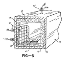
- Figure 3 is a schematic view, partly in section, illustrating the present invention utilized in a rectangular duct.
- Referring now to the drawings, attention is directed to Figures 1 and 2. These figures illustrate a
metallic duct 10 that, in the absence of the system of the present invention, would be exposed to a thin film of corrosive fluid such as a corrosive condensate. The interiormetallic surface 10a of the duct thus must be protected from corrosion. - As shown, the
duct 10 is lined along its interior surface with anabsorbent material 12 so that condensates which would otherwise form on the interior surface are absorbed byabsorbent lining 12. Thelining 12 must be resistant to the environment in which it is utilized. Specifically, it must satisfactorily resist chemical attack by the condensates it absorbs. The lining should also not detrimentally interact with the interior surface ofduct 10. - The
absorbent lining 12 is positioned by any appropriate means, such as by chemical bonding and mechanical fixation devices, in close contact with the interior surface of duct 10 (or, as described later, a non-conductive coating, 24) so that the interior surface is wetted by any condensates absorbed bylining 12. In the outlet duct of a sulfur dioxide scrubber in a fossil-fueled power plant,absorbent lining 12 may be a cementitious material such as Pennwalt Tufchem™ concrete manufactured by the Pennwalt Corporation of Delaware, Ohio. Alternatively, it may be possible to fabricateabsorbent lining 12 from a porous organic plastic material. - The system of the present invention further includes a
counterelectrode 14 placed in intimate contact with the surface ofabsorbent lining 12. By way of example, thecounterelectrode 14 is shown as a spirally-wound wire or rod. Other geometries, however, are possible and may be more appropriate depending on the particular configuration of the surface to be protected. For instance, a duct may have a square or rectangular cross-section (See Figure 3), requiring that the counterelectrode be constructed to correspond to such geometries. The counterelectrode could also comprise a conducting fabric. - It may be also necessary to embed
counterelectrode 14 into the surface of absorbent lining 12 (See Figure 3). This would be the case if the temperature gradient throughlining 12 is high enough such that the lining is wet near theduct wall 10a but dry at the surface contacting the gas or other corrosive fluid passing through the duct. Embeddingcounterelectrode 14 into theabsorbent lining 12 may also be a convenient method of providing structural support to the counterelectrode. - At intervals along the length of the duct, the duct is penetrated to make external connections to
counterelectrode 14. Such connections, indicated generally byreference numeral 16, are electrically-isolated from the duct wall andlining 12. Theelectrical connection 16 may comprise a tubular sleeve 16a through which is extended an electrically-conductive stud orbolt 16b. The tubular sleeve 16a extends through the duct wall and the absorbent lining. Sleeve 16a is fabricated from an electrically-insulating material such as Telfon manufactured by E. I. DuPont de Nemours Co. The electrically-conductive member 16b is appropriately positioned in sleeve 16a to be in contact withcounterelectrode 14 so that a conductive path is formed therebetween. Theelectrical connection 16 further includes anelectrical lead 16c that connects thecounterelectrode 14 in an electrical circuit with the electrical potential control ("EPC")system 22. Theelectrical lead 16c may extend through a suitable conduit (not illustrated). If appropriate,electrical connection 16 may be enclosed within a weathertight or gas-tight housing (also not illustrated). - The system of the present invention may also include a
reference electrode 18.Reference electrode 18 may be positioned at intervals along the length of theduct 10 at, or close to, the interface between lining 12 and theinterior surface 10a ofduct 10. The reference electrode is connected in circuit with theEPC system 22, and is electrically isolated fromduct 10. To this end,reference electrode 18 may extend through a tubular, electrically-insulating sleeve 18a to be in electrolytic contact with lining 12. An electrical lead 18b is provided to connect the reference electrode toEPC system 22. The electrical lead 18b may extend through an appropriate conduit and that portion ofreference electrode 18 exterior toduct 10, may be enclosed, if desired, within a weathertight or gas-tight housing. Neither the housing nor the conduit are illustrated. - The
duct 10 is connected in electrical circuit withEPC system 22 by means of ductelectrical connection 20.Connection 20 may comprise an electrically-conductive stud or member 20a disposed in electrically-conducting contact with the exterior wall ofduct 10. An appropriateelectrical lead 20b connects member 20a, and thusduct 10, in circuit withEPC system 22. - The specific construction of the
counterelectrode connection 16, thereference electrode 18 and theduct connection 20 would be readily apparent and well known to those of ordinary skill in the art, and hence the construction of these components are not illustrated nor described in any greater detail. - The
EPC system 22 is capable of controlling the electrochemical potential of the duct wall surface. For instance, if cathodic polarization is required,EPC system 22 would comprise a conventional cathodic protection system. However, as discussed heretofore, a cathodic protection system is just one possible electrochemical potential control system that may be utilized within the context of the present invention. - The essential feature of
EPC system 22 is that it is capable of passing current between the counterelectrode 14 and the duct wall (via duct connection 20) through the corrosive fluid absorbed inabsorbent lining 12, thereby providing control of the electrochemical potential of the duct wall to prevent corrosion. - If
reference electrode 18 is incorporated into the system, more precise control, as is well known in the art, of the electrochemical potential of the metallic surface ofduct 10 is possible. TheEPC system 22 measures the potential difference between the reference electrode and the duct surface, comparing that difference to a predetermined value. If the potential difference does not correspond to the predetermined or preset value, then the system automatically increases or decreases the current, as necessary, fromcounterelectrode 14 through the corrosive fluid inabsorbent lining 12 to the surface ofduct 10, until the measured potential difference between the reference electrode and the duct surface is equal to the preset value, i.e. the desired value for corrosion control. - The system of the present invention may be installed in stacks, ducts, or in any other areas that are exposed to corrosive condensates continuously or only intermittently. If
absorbent lining 12 is dry, little or no current will flow fromcounterelectrode 14 to the duct wall, because the dry lining is either poorly conducting or non-conducting. However, under such conditions, corrosion protection is not required, since corrosion rates are negligibly low if the duct wall is dry. - The absorbent lining allows currents to be passed from the counterelectrode to the metallic surface requiring protection from corrosion. Without
absorbent lining 12, it would be quite impractical, if not impossible, to pass such currents. The absorbent lining facilitates the required intimate contact between the counterelectrode and the corrosive fluid, while also eliminating the possibility of an electrical short-circuit between the counterelectrode and the metal surface being protected. - The system of the present invention may also include a non-conductive or poorly conducting
coating 24 disposed between the interior wall ofduct 10 andabsorbent lining 12. Thecoating 24 is, however, not located at those locations along the duct wherecounterelectrode connections 16 orreference electrode connections 18 exist. This is necessary in order to provide the appropriate electrolytic and electrical circuit path for operation of the system.Coating 24 is a corrosion-resistant coating, but is subjected to lower temperatures and may experience a less corrosive environment than lining 12. Thus, coating 24 may be constructed from a broader range of materials. For example, it may be fabricated from a material such as an epoxy, that might not be resistant to direct attack by the duct environment.Coating 24 provides additional protection toduct 10. It also provides a more economical system as less current and power would be utilized, since current only passes fromcounterelectrode 14 to the interior surface ofduct 10 at those points where there is a break (a "holiday") in thecoating 24. Holidays can be small (e.g. pinholes created during application of the coating) or large (e.g. caused by mechanical damage) but they are usually present. Thus, in the absence of the EPC system, thecoating 24 andabsorbent lining 12 alone cannot offer complete protection from corrosion. - Figure 3 illustrates the present invention utilized in a rectangular duct 10' with counterelectrode 14' embedded in absorbent layer 12'. Counterelectrode 14' has a square-mesh geometry, and as discussed, electrical connection 16' is provided to make external connections to counterelectrode 14'. Reference electrode 18' is in electrolytic contact with lining 12', and electrical connection 20' connects duct 10' in electrical circuit with the EPC system.
- The system of the present invention may be utilized in the outlet ducts and stacks of power plants. Additionally, the system may be utilized in various other situations where metallic surfaces are susceptible to corrosion by a thin surface layer of fluid. Such situations include those where the temperature of a gaseous environment drops below the dewpoint so that condensates form on the metallic surface to be protected. The system may also be utilized in splash zones often found at the junction between a liquid phase and a gas or vapor phase. For instance, the system of the present invention may be applied at the inlet of a sulfur dioxide scrubber where the limestone slurry may splash from the quench section into the inlet duct and cause severe corrosion. Similarly, the present invention may be used to protect structures partially immersed in corrosive fluids in cases where the fluid level continually or intermittently changes, for example in marine structures located in tidal zones. Here conventional protection systems would not provide adequate protection for surfaces that are wetted and are above the level of the bulk liquid.
- Although certain specific embodiments of the invention have been described herein in detail, the invention is not to be limited only to such embodiments, but rather only by the appended claims.
Claims (16)
- Apparatus for preventing corrosion of a metallic surface (10a) exposed to a corrosive fluid, the apparatus comprising a counterelectrode (14) located adjacent to and in contact with the corrosive fluid, and electrochemical potential control means (22) connected in circuit with said counterelectrode (14) and said surface (10a) for maintaining the potential of said surface (10a) at a predetermined value by passing a current between said counterelectrode (14) and said surface (10a) through the corrosive fluid, characterised in that an absorbent material (12) is disposed on said surface (10a) for absorbing the corrosive fluid, and the counterelectrode (14) is so located adjacent to and in contact with the absorbent material (12) that the said current passes through the corrosive fluid absorbed by the absorbent material (12).
- Apparatus according to claim 1, characterised in that the absorbent material is in the form of an absorbent lining (12) applied to said surface (10a).
- Apparatus according to claim 2, characterised by a reference electrode (18) in electrolytic contact with said lining (12) and electrically-insulated from said surface (10a) and said counterelectrode (14) except through corrosive condensate in said lining (12), and said electrochemical potential control means (22) also connected in electrical circuit with said reference electrode (18) for maintaining the potential of said surface (10a) at a predetermined value relative to said reference electrode (18).
- Apparatus according to claim 3, characterised in that the reference electrode (18) is disposed at intervals along the length of said surface (10a).
- Apparatus according to claim 1 or 2 or 3, characterised in that the counterelectrode (14') is embedded in said lining (12').
- Apparatus according to claim 1 or 2 or 3, characterised by an electrically non-conductive or poorly conductive, corrosion-resistant coating (24) disposed between said surface (10a) and said lining (12).
- Apparatus according to claim 2, characterised in that the lining (12) comprises a cementitious material.
- A method for preventing corrosion of a metallic surface (10a) by a corrosive fluid, comprising the step of maintaining the potential of the said surface (10a) at a predetermined value by passing a current between a counterelectrode (14), located in contact with the corrosive fluid, and the said surface (10a), through the said corrosive fluid, characterised in that the said corrosive fluid is absorbed by a layer (12) of absorbent material applied to the said surface (10a).
- A method according to claim 8, characterised by maintaining said potential at a predetermined value relative to a reference electrode (18) in electrolytic contact with said lining (12) and electrically-isolated from said surface (10a) and said counterelectrode (14) except through the corrosive fluid in said absorbent material (12).
- An apparatus for preventing corrosion of a metallic surface (10a) in a corrosive environment including:
an electrode (14), having the function of being a counterelectrode with respect to the metallic surface (10a), spaced from said metallic surface (10a) and positioned in contact with said environment; and
electrochemical potential control means (22) connected in an electrical circuit between said counterelectrode (14) and said metallic surface (10a) for maintaing an electric potential upon said metallic surface (10a) sufficient to effect cathodic protection of said metallic surface (10a) by passing a current from said counterelectrode (14) to said metallic surface (10a), characterised in that a corrosive condensate with a low pH tends to form on surfaces exposed to the environment, an absorbent lining (12) capable of absorbing the corrosive condensate and resistant to the corrosive effects of the corrosive condensate is provided on said metallic surface (10a) on the side of said surface (10a) facing the environment, said lining (12) being formed from a concrete material that has a chemical resistance to a low pH; and the said current passes through corrosive condensate absorbed by said absorbent lining (12). - Apparatus according to claim 10, characterised by an electrically non-conductive, corrosion-resistant coating (24) disposed between said metallic surface (10a) and said lining (12) which coating (24) has breaks that permit the passage of a current therethrough.
- Apparatus according to claim 10, characterised by:
a reference electrode (18) in electrolytic contact with said lining (12) and electrically-isolated from said metallic surface (10a) and from said counterelectrode (14) except through the corrosive condensate in said lining (12); and by
said electrochemical potential control means (22) being connected in electrical circuit with said counterelectrode (14), said reference electrode (18) and said metallic surface (10a) for maintaining the potential of said metallic surface (10a) at a predetermined cathodic protection value with respect to said reference electrode (18). - Apparatus according to claims 10, 11 or 12, characterised in that the apparatus is provided in the form of a flue gas duct or stack and in that the metallic surface (10a) is an interior facing surface of metal forming the duct or stack.
- A method for a cathodic protection in a corrosive environment in which corrosion of a metallic surface would occur in the absence of said method, comprising:
inducing an electrochemical potential between said metallic surface (10a) and the corrosive environment sufficient to effect cathodic protection of the metallic surface (10a), characterised by
applying to the side of the metallic surface (10a) facing the corrosive environment a layer (12) of an acid resistant concrete that has a chemical resistance to a low pH and permits cathodic protection, the said environment comprising a low pH corrosive condensate; and
absorbing the corrosive condensate in said layer (12) of acid resistant concrete, the said electrochemical potential being induced through the absorbed condensate in said layer (12). - A method according to claim 14, characterised in that the electrochemical potential induced is maintained at a predetermined value controlled by a reference electrode (18).
- A method according to claim 14 or 15 characterised in that the low pH environment is the interior environment of a flue gas duct or stack and in that the layer of an acid resistant concrete is applied to the interior facing surface (10a) of the duct or stack.
Priority Applications (1)
| Application Number | Priority Date | Filing Date | Title |
|---|---|---|---|
| AT87304065T ATE77694T1 (en) | 1986-05-16 | 1987-05-07 | SYSTEM FOR CONTROLLING CORROSION CAUSED BY THIN LAYERS OF CORROSIVE FLUID. |
Applications Claiming Priority (2)
| Application Number | Priority Date | Filing Date | Title |
|---|---|---|---|
| US86373686A | 1986-05-16 | 1986-05-16 | |
| US863736 | 1986-05-16 |
Publications (3)
| Publication Number | Publication Date |
|---|---|
| EP0246029A2 EP0246029A2 (en) | 1987-11-19 |
| EP0246029A3 EP0246029A3 (en) | 1989-05-10 |
| EP0246029B1 true EP0246029B1 (en) | 1992-06-24 |
Family
ID=25341675
Family Applications (1)
| Application Number | Title | Priority Date | Filing Date |
|---|---|---|---|
| EP87304065A Expired - Lifetime EP0246029B1 (en) | 1986-05-16 | 1987-05-07 | A system for controlling corrosion by thin layers of corrosive fluids |
Country Status (4)
| Country | Link |
|---|---|
| EP (1) | EP0246029B1 (en) |
| AT (1) | ATE77694T1 (en) |
| CA (1) | CA1334518C (en) |
| DE (1) | DE3779960T2 (en) |
Families Citing this family (4)
| Publication number | Priority date | Publication date | Assignee | Title |
|---|---|---|---|---|
| BE1000513A3 (en) * | 1987-05-07 | 1989-01-10 | Bekaert Sa Nv | Method for corrosion. |
| US6320395B1 (en) | 1999-06-16 | 2001-11-20 | Katholieke Universiteit Leuven | Apparatus and method for electrochemical corrosion monitoring |
| WO2014130034A1 (en) * | 2013-02-21 | 2014-08-28 | Empire Technology Development Llc | Corrosion control for supercritical water gasification components |
| DE102015104794A1 (en) | 2015-03-27 | 2016-09-29 | Epcos Ag | Inductive component and method for producing an inductive component |
Family Cites Families (1)
| Publication number | Priority date | Publication date | Assignee | Title |
|---|---|---|---|---|
| DK626474A (en) * | 1974-12-03 | 1976-06-04 | Guldager Electrolyse | PROCEDURE FOR ROGGAS CLEANING AND PROCEDURE |
-
1987
- 1987-05-04 CA CA000536260A patent/CA1334518C/en not_active Expired - Fee Related
- 1987-05-07 DE DE8787304065T patent/DE3779960T2/en not_active Expired - Fee Related
- 1987-05-07 AT AT87304065T patent/ATE77694T1/en active
- 1987-05-07 EP EP87304065A patent/EP0246029B1/en not_active Expired - Lifetime
Also Published As
| Publication number | Publication date |
|---|---|
| ATE77694T1 (en) | 1992-07-15 |
| EP0246029A2 (en) | 1987-11-19 |
| EP0246029A3 (en) | 1989-05-10 |
| DE3779960D1 (en) | 1992-07-30 |
| CA1334518C (en) | 1995-02-21 |
| DE3779960T2 (en) | 1992-12-24 |
Similar Documents
| Publication | Publication Date | Title |
|---|---|---|
| US5290407A (en) | System for controlling corrosion in an environment in which thin layers of low-pH corrosive fluids are formed | |
| CA2423116C (en) | Doubly-protected reinforcing members in concrete | |
| CA1211074A (en) | Cathodic protection apparatus for well coated metal vessels having a gross bare area | |
| EP0246029B1 (en) | A system for controlling corrosion by thin layers of corrosive fluids | |
| ATE46925T1 (en) | ANTI-CORROSION SYSTEM. | |
| US4381981A (en) | Sacrificial cathodic protection system | |
| US4445989A (en) | Ceramic anodes for corrosion protection | |
| KR20130046874A (en) | Hybrid type cathode protection system and method using iccp type and sacrificial anode type cathode protection technologies for marine concrete structure | |
| Freiman et al. | Model investigation of the peculiarities of the corrosion and cathodic protection of steel in the insulation defects on underground steel pipelines | |
| US3182007A (en) | Electrode assembly for the anodic passivation of metals | |
| KR100485953B1 (en) | Method for cathodic protection for metal structure | |
| US7186327B1 (en) | Method and apparatus for scaling control and in-situ cathodic protection | |
| US7198707B2 (en) | Apparatus for cathodic protection in an environment in which thin film corrosive fluids are formed and method thereof | |
| JPS61124863A (en) | Method for measuring potential of reinforcing bar in concrete | |
| US5795994A (en) | Process and apparatus for measuring condensed moisture and applications thereof | |
| EP0324440A1 (en) | Cathodic protection apparatus in systems for the circulation of corrosive liquids | |
| US20020096438A1 (en) | Method and apparatus for cathodically protecting reinforced concrete structures | |
| JPS6456888A (en) | Corrosion preventing method for steel casing pipe and buried pipe using the same | |
| Munro et al. | Anodic Protection of White & Green Liquor Tankage With and Without the Use of Protective Organic Linings | |
| Lehmann | Control of Corrosion in Water Systems | |
| KR100505278B1 (en) | Anode Assembly for cathodic protection in an environment in which thin film corrosive fluids are formed | |
| WO2013062234A1 (en) | Iccp system for offshore concrete structure | |
| Montillon | Corrosion and Cathodic Protection | |
| WO1985003311A1 (en) | Cathodic protection monitoring method and device | |
| JPH0630851Y2 (en) | Horizontal pipe cathodic protection |
Legal Events
| Date | Code | Title | Description |
|---|---|---|---|
| PUAI | Public reference made under article 153(3) epc to a published international application that has entered the european phase |
Free format text: ORIGINAL CODE: 0009012 |
|
| AK | Designated contracting states |
Kind code of ref document: A2 Designated state(s): AT DE GB NL |
|
| PUAL | Search report despatched |
Free format text: ORIGINAL CODE: 0009013 |
|
| AK | Designated contracting states |
Kind code of ref document: A3 Designated state(s): AT DE GB NL |
|
| 17P | Request for examination filed |
Effective date: 19890922 |
|
| 17Q | First examination report despatched |
Effective date: 19901019 |
|
| GRAA | (expected) grant |
Free format text: ORIGINAL CODE: 0009210 |
|
| AK | Designated contracting states |
Kind code of ref document: B1 Designated state(s): AT DE GB NL |
|
| PG25 | Lapsed in a contracting state [announced via postgrant information from national office to epo] |
Ref country code: NL Effective date: 19920624 Ref country code: AT Effective date: 19920624 |
|
| REF | Corresponds to: |
Ref document number: 77694 Country of ref document: AT Date of ref document: 19920715 Kind code of ref document: T |
|
| REF | Corresponds to: |
Ref document number: 3779960 Country of ref document: DE Date of ref document: 19920730 |
|
| NLV1 | Nl: lapsed or annulled due to failure to fulfill the requirements of art. 29p and 29m of the patents act | ||
| PLBE | No opposition filed within time limit |
Free format text: ORIGINAL CODE: 0009261 |
|
| STAA | Information on the status of an ep patent application or granted ep patent |
Free format text: STATUS: NO OPPOSITION FILED WITHIN TIME LIMIT |
|
| 26N | No opposition filed | ||
| PGFP | Annual fee paid to national office [announced via postgrant information from national office to epo] |
Ref country code: DE Payment date: 19950526 Year of fee payment: 9 |
|
| PGFP | Annual fee paid to national office [announced via postgrant information from national office to epo] |
Ref country code: GB Payment date: 19950530 Year of fee payment: 9 |
|
| PG25 | Lapsed in a contracting state [announced via postgrant information from national office to epo] |
Ref country code: GB Effective date: 19960507 |
|
| GBPC | Gb: european patent ceased through non-payment of renewal fee |
Effective date: 19960507 |
|
| PG25 | Lapsed in a contracting state [announced via postgrant information from national office to epo] |
Ref country code: DE Effective date: 19970201 |