EP0245666B1 - Turn tilt table - Google Patents
Turn tilt table Download PDFInfo
- Publication number
- EP0245666B1 EP0245666B1 EP87105486A EP87105486A EP0245666B1 EP 0245666 B1 EP0245666 B1 EP 0245666B1 EP 87105486 A EP87105486 A EP 87105486A EP 87105486 A EP87105486 A EP 87105486A EP 0245666 B1 EP0245666 B1 EP 0245666B1
- Authority
- EP
- European Patent Office
- Prior art keywords
- vehicle
- frame
- turntable
- leveling
- platform
- Prior art date
- Legal status (The legal status is an assumption and is not a legal conclusion. Google has not performed a legal analysis and makes no representation as to the accuracy of the status listed.)
- Expired
Links
- 238000012360 testing method Methods 0.000 claims description 48
- 239000003638 chemical reducing agent Substances 0.000 claims description 3
- 230000005484 gravity Effects 0.000 claims description 3
- 238000000034 method Methods 0.000 claims description 3
- 238000005303 weighing Methods 0.000 claims description 3
- NJPPVKZQTLUDBO-UHFFFAOYSA-N novaluron Chemical compound C1=C(Cl)C(OC(F)(F)C(OC(F)(F)F)F)=CC=C1NC(=O)NC(=O)C1=C(F)C=CC=C1F NJPPVKZQTLUDBO-UHFFFAOYSA-N 0.000 claims description 2
- 230000003213 activating effect Effects 0.000 claims 2
- 238000004873 anchoring Methods 0.000 claims 2
- 230000000087 stabilizing effect Effects 0.000 claims 1
- 239000012530 fluid Substances 0.000 description 5
- 230000002706 hydrostatic effect Effects 0.000 description 2
- 238000010586 diagram Methods 0.000 description 1
- 239000012634 fragment Substances 0.000 description 1
- 238000012986 modification Methods 0.000 description 1
- 230000004048 modification Effects 0.000 description 1
- 230000007935 neutral effect Effects 0.000 description 1
- 230000001681 protective effect Effects 0.000 description 1
- 239000007858 starting material Substances 0.000 description 1
Images




Classifications
-
- F—MECHANICAL ENGINEERING; LIGHTING; HEATING; WEAPONS; BLASTING
- F41—WEAPONS
- F41A—FUNCTIONAL FEATURES OR DETAILS COMMON TO BOTH SMALLARMS AND ORDNANCE, e.g. CANNONS; MOUNTINGS FOR SMALLARMS OR ORDNANCE
- F41A23/00—Gun mountings, e.g. on vehicles; Disposition of guns on vehicles
- F41A23/26—Mountings for transport only; Loading or unloading arrangements for guns for use with carrier vehicles
-
- B—PERFORMING OPERATIONS; TRANSPORTING
- B66—HOISTING; LIFTING; HAULING
- B66F—HOISTING, LIFTING, HAULING OR PUSHING, NOT OTHERWISE PROVIDED FOR, e.g. DEVICES WHICH APPLY A LIFTING OR PUSHING FORCE DIRECTLY TO THE SURFACE OF A LOAD
- B66F7/00—Lifting frames, e.g. for lifting vehicles; Platform lifts
- B66F7/22—Lifting frames, e.g. for lifting vehicles; Platform lifts with tiltable platforms
-
- B—PERFORMING OPERATIONS; TRANSPORTING
- B66—HOISTING; LIFTING; HAULING
- B66F—HOISTING, LIFTING, HAULING OR PUSHING, NOT OTHERWISE PROVIDED FOR, e.g. DEVICES WHICH APPLY A LIFTING OR PUSHING FORCE DIRECTLY TO THE SURFACE OF A LOAD
- B66F7/00—Lifting frames, e.g. for lifting vehicles; Platform lifts
- B66F7/24—Lifting frames, e.g. for lifting vehicles; Platform lifts for raising or lowering vehicles by their own power
- B66F7/243—Ramps
Definitions
- the present invention relates to a turn tilt table on a self propelled vehicle, and more particularly relates to such a turn tilt table for rotating objects such as a military vehicle through 360 ° while tilting the military vehicle between a horizontal position and 45 from the horizontal.
- the turn tilt table of the present invention is intended to support a test vehicle (hereinafter termed a military vehicle) weighing up to about 70 tons, and to rotate the table and military vehicle to any of a plurality of positions within 3600, and to tilt the table and military vehicle thereon between a horizontal position and a position that is tilted between 0 and 45 from the horizontal.
- the turn tilt table with the military vehicle rigidly secured to the table is positioned in a test area including a control tower from which a line of sight to the vehicle may be taken which line of sight includes a radar beam or other beam directed at the test vehicle.
- the military vehicle is rotated and tilted to present all detectable upright and top surfaces to the beam for the purpose of determining which surface finish or configuration is best to prevent an enemy from detecting the vehicle during combat by radar or the like, or determining the vehicle radar signatures.
- the turn tilt table vehicle is moved to different locations at the test area so that the effectiveness of the surface finish can be determined at different horizontal and vertical angles from the tower and also at ranges up to at least three kilometers. If the military vehicle being tested is relatively light, such as a one-half ton vehicle or an M113 personnel carrier, the turn tilt table vehicle may be driven to different locations in the test area while carrying the military vehicle at a time when the turn tilt table is in a horizontal position.
- the turn tilt vehicle may carry the military vehicle to different locations in the test area provided the vehicle supporting surface has a density sufficient to support the load.
- Towable ramps are also provided for connection to the turn tilt table thereby enabling the military vehicle to be driven up the ramps onto the turn tilt table.
- the turn tilt table vehicle 20 (Figs. 1, 2, 4 and 5) of the present invention comprises a pair of tread members or tracks 22,24 each having hydraulic motors 26,28 (Fig. 2) for driving the tracks.
- the tracks are connected to a leveling frame 36 by tubular connectors 34 which may be removed from the leveling frame 36 to reduce the overall width of the leveling frame when the vehicle is broken down into several components for shipment by truck or by rail to different locations.
- the leveling frame 36 is rigidly connected to outrigger beams 40,42.
- Hydraulically actuated jack cylinders 46 having pontoons 48 on the lower ends of piston rods 49 are mounted on the ends of the outrigger beams 40,42 for leveling the frame 36 and components supported thereon when in testing position on the test area.
- An engine 50 and hydraulic pumps 52 are supported on the leveling frame 36 to provide hydraulic power to the track motors 26,28; to the leveling jack cylinders 46 and to other hydraulic components to be described hereinafter.
- a tilting frame 54 is pivotally attached to lugs 56 on the leveling frame 36 by pins 58.
- the tilting frame is pivoted between a horizontal position and a tilted position of up to about 45 by a pair of hydraulic tilt cylinders 60 that are pivotally connected between the leveling frame 36 and the tilting frame 54 as best shown in Figure 1.
- the tilting frame 54 supports a large diameter turntable bearing 64 having an upper rotatable portion 66 with gear teeth on its outer periphery which engage a pinion gear 68 (Fig. 1) driven by a hydraulic motor and reducer 70.
- a rotating platform 72 (Figs.
- the rotating platform 72 includes a track or wheel engaging bed 74 upon which the military vehicle MV to be tested is supported.
- the bed 74 is secured to a plurality of longitudinally extending beams (not shown) and a plurality of transverse beams 76 (Fig. 1) which support the track or wheel engaging bed 74 upon the upper rotatable portion 66 of the turntable bearing 64.
- an operator station 80 is provided at the rear of the vehicle 20.
- the operator station includes framework 82 defining an operator's box 84 having an opening on its left side to permit an operator to enter and exit the box.
- the box 84 is pivotally supported on the rear outrigger beam 42 by a pivot pin 86.
- a latching rod 88 is removed from the lugs 90,92 on the outrigger beam 42 and the box 84 allowing the box to be pivoted to the phantom line position in Figure 2 thus simplifying the break down and transportation procedure.
- Conventional engine gauges, switches, and controls include; an ignition/starter button, a throttle lever, travel control and emergency shutdown controls mounted at the operator's station 80.
- Two live-dead switches are provided at the operator's station 80 with the first live-dead switch providing and denying power to hydraulic functions, i.e., swing, tilt, and outrigger jack controls.
- the second live-dead switch provides or denies power to the travel circuit thus insuring that the vehicle cannot travel during tests or when improperly positioned.
- a two section towable mobile loading ramp 100 (Figs. 6-13) is provided to permit the military vehicle MV being tested to drive up the ramp 100 onto the rotating platform 72 and be parked with the center of gravity of the military vehicle being substantially centered on the vertical axis of rotation A of the rotating platform 72 and tilting frame 54 when horizontal.
- Each section 100a,100b of the ramp 100 is identical, and is in the form of a relatively narrow two wheel trailer which is independently towed to and connected in its operative position as indicated in Figures 9-12. Accordingly, only the ramp section 100a will be described in detail.
- the ramp section 100a comprises an inclined portion 102 having a tongue 103 bolted on its lower end and connected to a towing vehicle 104 by a connector 106.
- the upper end of the inclined portion is rigidly connected to a generally horizontal portion 108.
- a pair of wheels 109 (Fig. 13) are journaled on an axle 110, and the axle is rigidly secured to arms 112 that are connected to the inclined portion 102 of the ramp 100a for pivotal movement about axis C.
- the arms 112 are strengthened by diagonal members 113.
- a hydraulic cylinder 114 is pivotally connected between the axle 110 and the inclined portion 102 and may be controlled to raise or lower the ramp section 100a relative to the ground.
- traction bars 116 (Fig. 7) and angle guide rails 118 are welded to the inclined portion 102 and to the horizontal portion 108 of the ramp section 100a.
- a pair of legs 120 are welded to the inclined portion 102 of the ramp section 100a and cooperate with bumpers 122 welded to the axle 110 to support the ramp section 100a on the axle when the hydraulic cylinder 114 is fully retracted and is disconnected from its source of hydraulic fluid. As best shown in Figures 10-12 the cylinder 114 receives its hydraulic fluid through quick connect conduit 123, connected to the hydraulic circuit nearly centered between rear outrigger jacks 46.
- an associated vertical plate 124 (Figs. 8 and 14) is welded to and projects downwardly and rearwardly from the horizontal portion 108 and is guided between a pair of spaced V-shaped plates 126,128 (Fig. 3).
- the spaced plates are welded to the rear wall of the rotating platform 72 and are reinforced by gussets 130,132 having slots 134 therein.
- a hole 136 in the vertical plate 124 is aligned with the slots 134 when the ramp section 100a is in position to be attached to the rotating platform 72 and receives a pin 138 which is held in place by cotter pins or the like.
- a pair of bars 140 are welded to the rear end of the horizontal portion 108 of the ramp section 100a and operatively engage and are supported by a pair of hooks 142 on the rotating platform 72 to transfer the weight of a portion of the ramp section 100a and the military vehicle MV thereon to the rear end of the rotating platform 72 when the pin 138 connects the rotating platform to the ramp section 100a.
- a pair of pedestals 150 (Figs. 8 and 15) and shims 152 are bolted to the leveling frame 36.
- the upper end of each pedestal 150 removably receives a pin 153 to which a pair of links 154 are attached and held in place by cotter pins or the like.
- the upper ends of the links 154 are removably received on a second pin 156 which is slidably received in a collar 157 welded to the rotary platform 72 and is held in place by connectors such as cotter pins.
- a plurality of hold down arms 164 are bolted to the rotatable platform 72 in appropriate positions to supportively attach the particular type of vehicle being tested to the rotating platform 72.
- each hold down arm 164 When handling the illustrated military vehicle MV, each hold down arm 164 includes a sturdy box beam body 165 bolted to the rotating platform 72 and has an upturned end portion 166. Vehicle connecting brackets 168,170 are connected to lugs (not shown) on the vehicle MV as by pinning or bolting. The brackets 168,170 and a required number of shims 172,174 are then bolted to the upturned end portion 166 of the associated hold down arm 164. Secured in this way, the vehicle MV may be turned and tilted to a plurality of positions, including those positions illustrated in Figures 1, 4 and 5.
- the hydraulic components for driving the tracks 22,24 are conventional in the art being the same as that used in Assignee's LS-7400A Crawler Hydraulic Excavator.
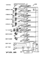
- a simplified hydraulic circuit 200 is provided to support the claims, and is illustrated in Figure 16 as providing means for operating the turn table vehicle 20. It will be understood that certain protective circuits, check valves, and other conventional hydraulic circuitry have been omitted from the illustrated hydraulic circuit for simplicity.
- the circuit 200 includes a pump P driven by the engine and gearcase 50 which directs high pressure hydraulic fluid through main conduit HP and returns the fluid to a tank T through low pressure conduit LP.
- a pilot operated relief valve 202 opens and returns the fluid to tank T in the event the pressure in line HP exceeds a predetermined pressure.
- a plurality of manually or electrically operated valves V1-V8 are connected to the high pressure and low pressure conduits, and are returned to their illustrated neutral positions by spring 204.
- the track drive motors 26 and 28 are preferably hydrostatic motors driven by hydrostatic pumps controlled by an operator with conventional controls.
- the turntable motor 70 rotates the platform 72 in o ne direction when the valve V1 is shifted to its parallel passage position, and in the opposite direction when shifted to the cross passage position When the valve V1 is in its illustrated central position, the motor 70 is hydraulically locked in fixed position.
- the four hydraulic jacks 46 are independently raised when valves V2-V5 are independently moved to the parallel passage position, and are lowered when the associated valves V2-V5 are moved to the cross passage position.
- the tilt cylinders 60 are raised when the valve V6 is moved to the parallel passage position and are lowered when the valve V6 is moved to the cross passage position.
- the two ramp cylinders 114 for the two ramps 100 are independently retraated when the associated valves V7,V8 are in their parallel passage position, and are independently extended when the valves V7,V8 are moved to the cross passage position.
- a control tower 206 (Fig. 17) is placed in a test area 208 within which the turn tilt table vehicle 20, with a test object such as the military vehicle MV secured thereto, is driven to a plurality of different test locations.
- a radar beam 210 or the like is directed from the tower 206 at the test vehicle MV when in said plurality of locations to determine vehicle radar signatures or the like.
- the test vehicle may be spaced 3 kilometers away from the tower 206 or at any desired position closer to the tower. While at each test position the test vehicle MV may be tilted to any position between horizontal and the 45 position, and may be rotated to any desired position within the 360 range of rotation.
- a shield 214 may be placed between the tower and a major portion of the turn tilt table vehicle 20 thus exposing only the military vehicle to the beam.
- the self propelled turn tilt table vehicle of the present invention is capable of driving to different locations and supporting an article to be tested such as a military vehicle weighing up to about 70 tons.
- a loading ramp may be connected to the turn tilt table vehicle for allowing a test vehicle to be driven onto or off the turn tilt table vehicle.
- the turn tilt vehicle is capable of tilting a rotating platform to which the test vehicle is rigidly secured to anywhere between a horizontal position and a position tilting the vehicle up to about 45 from horizontal. While in the horizontal position, or any one of the tilted positions, the rotating platform and the test article or vehicle attached thereto may be rotated through 360 ° to test the surface finish of the article or vehicle for determining vehicle radar signatures or the like.
Landscapes
- Engineering & Computer Science (AREA)
- Life Sciences & Earth Sciences (AREA)
- Geology (AREA)
- Mechanical Engineering (AREA)
- Structural Engineering (AREA)
- General Engineering & Computer Science (AREA)
- Vehicle Cleaning, Maintenance, Repair, Refitting, And Outriggers (AREA)
- Geophysics And Detection Of Objects (AREA)
- Handcart (AREA)
Description
- The present invention relates to a turn tilt table on a self propelled vehicle, and more particularly relates to such a turn tilt table for rotating objects such as a military vehicle through 360 ° while tilting the military vehicle between a horizontal position and 45 from the horizontal.
- The turn tilt table of the present invention is intended to support a test vehicle (hereinafter termed a military vehicle) weighing up to about 70 tons, and to rotate the table and military vehicle to any of a plurality of positions within 3600, and to tilt the table and military vehicle thereon between a horizontal position and a position that is tilted between 0 and 45 from the horizontal. The turn tilt table with the military vehicle rigidly secured to the table is positioned in a test area including a control tower from which a line of sight to the vehicle may be taken which line of sight includes a radar beam or other beam directed at the test vehicle. The military vehicle is rotated and tilted to present all detectable upright and top surfaces to the beam for the purpose of determining which surface finish or configuration is best to prevent an enemy from detecting the vehicle during combat by radar or the like, or determining the vehicle radar signatures. The turn tilt table vehicle is moved to different locations at the test area so that the effectiveness of the surface finish can be determined at different horizontal and vertical angles from the tower and also at ranges up to at least three kilometers. If the military vehicle being tested is relatively light, such as a one-half ton vehicle or an M113 personnel carrier, the turn tilt table vehicle may be driven to different locations in the test area while carrying the military vehicle at a time when the turn tilt table is in a horizontal position. When a 70 ton tank or the like is being tested, the turn tilt vehicle may carry the military vehicle to different locations in the test area provided the vehicle supporting surface has a density sufficient to support the load. Towable ramps are also provided for connection to the turn tilt table thereby enabling the military vehicle to be driven up the ramps onto the turn tilt table.
-
- Figure 1 is a side elevation of the turn tilt table vehicle illustrating the turn tilt table in a horizontal position in solid lines, and tilted 45 with a military vehicle secured thereto in phantom lines.
- Figure 2 is a plan of the turn tilt table vehicle with the turn tilt table and the tracks outlined in phantom lines, and other components of the vehicle being shown in dotted lines.
- Figure 3 is a perspective of the turn tilt table in a horizontal position illustrating four hold down beams in position to secure a vehicle to the table.
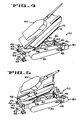
- Figure 4 is a diagrammatic perspective illustrating a military vehicle tilted upwardly about 30°.
- Figure 5 is a diagrammatic perspective illustrating a military vehicle tilted to about 30 and rotated about 45 ° .
- Figure 6 is a diagrammatic perspective illustrating a military vehicle being driven up a two section towable ramp onto the turn tilt table.
- Figure 7 is an enlarged side elevation illustrating a fragment of the turn tilt table and a portion of the ramp showing the structure for attaching the ramp to the table and further illustrating the structure to prevent the weight of the vehicle from deflecting the table.
- Figure 8 is a section taken along lines 8-8 of Figure 7 with a pair of hold down beams shown in phantom.
- Figure 9 is an operational view illustrating the towable mobile ramps being pushed into position to be connected to the turn tilt table vehicle, said ramp being connected to a towing vehicle.
- Figure 10 is an operational view illustrating the upper end of the ramp being hydraulically lowered for pivotal connection to the turn tilt table.
- Figure 11 illustrates the ramp coupled to the rotatable table with its other end hydraulically raised and disconnected from the towing vehicle.
- Figure 12 illustrates the forward end of the ramp supported on the ground with its tongue removed from the ramp and the towing vehicle.
- Figure 13 is an enlarged section taken along lines 13-13 of Figure 9, illustrating one of two ramp sections supported on two wheels.
- Figure 14 is an enlarged section taken along lines 14-14 of Figure 8.
- Figure 15 is an enlarged section taken along lines 15-15 of Figure 8.
- Figure 16 is a hydraulic diagram illustrating a simplified hydraulic circuit.
- Figure 17 is a plan view illustrating a test field having a tower from which a radar beam or the like is directed at the military vehicle being tested when at several different locations.
- The turn tilt table vehicle 20 (Figs. 1, 2, 4 and 5) of the present invention comprises a pair of tread members or
tracks hydraulic motors 26,28 (Fig. 2) for driving the tracks. The tracks are connected to aleveling frame 36 bytubular connectors 34 which may be removed from theleveling frame 36 to reduce the overall width of the leveling frame when the vehicle is broken down into several components for shipment by truck or by rail to different locations. - The leveling
frame 36 is rigidly connected tooutrigger beams jack cylinders 46 havingpontoons 48 on the lower ends ofpiston rods 49 are mounted on the ends of theoutrigger beams frame 36 and components supported thereon when in testing position on the test area. Anengine 50 andhydraulic pumps 52 are supported on the levelingframe 36 to provide hydraulic power to thetrack motors jack cylinders 46 and to other hydraulic components to be described hereinafter. - A tilting
frame 54 is pivotally attached tolugs 56 on the levelingframe 36 bypins 58. The tilting frame is pivoted between a horizontal position and a tilted position of up to about 45 by a pair ofhydraulic tilt cylinders 60 that are pivotally connected between theleveling frame 36 and the tiltingframe 54 as best shown in Figure 1. The tiltingframe 54 supports a large diameter turntable bearing 64 having an upperrotatable portion 66 with gear teeth on its outer periphery which engage a pinion gear 68 (Fig. 1) driven by a hydraulic motor and reducer 70. When in its horizontal solid line position of Figure 1, the tiltingframe 54 androtatable portion 66 of thebearing 64 rotates about a vertical axis A. A rotating platform 72 (Figs. 1-3) is rigidly secured to therotatable portion 66 of the turntable bearing 64. Therotating platform 72 includes a track or wheelengaging bed 74 upon which the military vehicle MV to be tested is supported. Thebed 74 is secured to a plurality of longitudinally extending beams (not shown) and a plurality of transverse beams 76 (Fig. 1) which support the track or wheelengaging bed 74 upon the upperrotatable portion 66 of the turntable bearing 64. As best shown in Figures 1 and 2, anoperator station 80 is provided at the rear of thevehicle 20. The operator station includesframework 82 defining an operator'sbox 84 having an opening on its left side to permit an operator to enter and exit the box. Thebox 84 is pivotally supported on therear outrigger beam 42 by apivot pin 86. - When the vehicle is to be broken down and transported long distances to different locations by truck or by rail, a
latching rod 88 is removed from thelugs outrigger beam 42 and thebox 84 allowing the box to be pivoted to the phantom line position in Figure 2 thus simplifying the break down and transportation procedure. Conventional engine gauges, switches, and controls include; an ignition/starter button, a throttle lever, travel control and emergency shutdown controls mounted at the operator'sstation 80. Two live-dead switches are provided at the operator'sstation 80 with the first live-dead switch providing and denying power to hydraulic functions, i.e., swing, tilt, and outrigger jack controls. The second live-dead switch provides or denies power to the travel circuit thus insuring that the vehicle cannot travel during tests or when improperly positioned. - A two section towable mobile loading ramp 100 (Figs. 6-13) is provided to permit the military vehicle MV being tested to drive up the
ramp 100 onto therotating platform 72 and be parked with the center of gravity of the military vehicle being substantially centered on the vertical axis of rotation A of therotating platform 72 and tiltingframe 54 when horizontal. - Each
section ramp 100 is identical, and is in the form of a relatively narrow two wheel trailer which is independently towed to and connected in its operative position as indicated in Figures 9-12. Accordingly, only theramp section 100a will be described in detail. - The
ramp section 100a comprises aninclined portion 102 having atongue 103 bolted on its lower end and connected to atowing vehicle 104 by aconnector 106. The upper end of the inclined portion is rigidly connected to a generallyhorizontal portion 108. A pair of wheels 109 (Fig. 13) are journaled on anaxle 110, and the axle is rigidly secured toarms 112 that are connected to theinclined portion 102 of theramp 100a for pivotal movement about axis C. Thearms 112 are strengthened bydiagonal members 113. Ahydraulic cylinder 114 is pivotally connected between theaxle 110 and theinclined portion 102 and may be controlled to raise or lower theramp section 100a relative to the ground. In order to maintain control of the military vehicle MV when driven up or down the ramp, traction bars 116 (Fig. 7) andangle guide rails 118 are welded to theinclined portion 102 and to thehorizontal portion 108 of theramp section 100a. - A pair of
legs 120 are welded to theinclined portion 102 of theramp section 100a and cooperate withbumpers 122 welded to theaxle 110 to support theramp section 100a on the axle when thehydraulic cylinder 114 is fully retracted and is disconnected from its source of hydraulic fluid. As best shown in Figures 10-12 thecylinder 114 receives its hydraulic fluid throughquick connect conduit 123, connected to the hydraulic circuit nearly centered betweenrear outrigger jacks 46. - In order to connect each of the two sections of the
ramp 100 to therotating platform 72, an associated vertical plate 124 (Figs. 8 and 14) is welded to and projects downwardly and rearwardly from thehorizontal portion 108 and is guided between a pair of spaced V-shaped plates 126,128 (Fig. 3). The spaced plates are welded to the rear wall of the rotatingplatform 72 and are reinforced by gussets 130,132 havingslots 134 therein. Ahole 136 in thevertical plate 124 is aligned with theslots 134 when theramp section 100a is in position to be attached to the rotatingplatform 72 and receives apin 138 which is held in place by cotter pins or the like. - Having reference to Figures 7 and 8, a pair of
bars 140 are welded to the rear end of thehorizontal portion 108 of theramp section 100a and operatively engage and are supported by a pair ofhooks 142 on the rotatingplatform 72 to transfer the weight of a portion of theramp section 100a and the military vehicle MV thereon to the rear end of the rotatingplatform 72 when thepin 138 connects the rotating platform to theramp section 100a. - In order to prevent the weight of the military vehicle MV from deflecting the rotating
platform 72 downwardly when the vehicle is being driven onto or off the rotating platform, a pair of pedestals 150 (Figs. 8 and 15) andshims 152 are bolted to the levelingframe 36. The upper end of eachpedestal 150 removably receives apin 153 to which a pair oflinks 154 are attached and held in place by cotter pins or the like. The upper ends of thelinks 154 are removably received on asecond pin 156 which is slidably received in acollar 157 welded to therotary platform 72 and is held in place by connectors such as cotter pins. After the military vehicle has been driven onto the rotatingplatform 72 and its center of gravity is in approximate alignment with the axis A of thebearing 64, pins 156 are removed from the rotatingplatform 72 andlinks 154 pivoted downward to a storage position. - As best illustrated in Figures 1 and 3, a plurality of hold down
arms 164 are bolted to therotatable platform 72 in appropriate positions to supportively attach the particular type of vehicle being tested to therotating platform 72. - When handling the illustrated military vehicle MV, each hold down
arm 164 includes a sturdybox beam body 165 bolted to therotating platform 72 and has anupturned end portion 166. Vehicle connecting brackets 168,170 are connected to lugs (not shown) on the vehicle MV as by pinning or bolting. The brackets 168,170 and a required number of shims 172,174 are then bolted to theupturned end portion 166 of the associated hold downarm 164. Secured in this way, the vehicle MV may be turned and tilted to a plurality of positions, including those positions illustrated in Figures 1, 4 and 5. - The hydraulic components for driving the
tracks hydraulic circuit 200 is provided to support the claims, and is illustrated in Figure 16 as providing means for operating theturn table vehicle 20. It will be understood that certain protective circuits, check valves, and other conventional hydraulic circuitry have been omitted from the illustrated hydraulic circuit for simplicity. - The
circuit 200 includes a pump P driven by the engine andgearcase 50 which directs high pressure hydraulic fluid through main conduit HP and returns the fluid to a tank T through low pressure conduit LP. A pilot operatedrelief valve 202 opens and returns the fluid to tank T in the event the pressure in line HP exceeds a predetermined pressure. A plurality of manually or electrically operated valves V1-V8 are connected to the high pressure and low pressure conduits, and are returned to their illustrated neutral positions byspring 204. - The
track drive motors turntable motor 70 rotates theplatform 72 in o ne direction when the valve V1 is shifted to its parallel passage position, and in the opposite direction when shifted to the cross passage position When the valve V1 is in its illustrated central position, themotor 70 is hydraulically locked in fixed position. - The four
hydraulic jacks 46 are independently raised when valves V2-V5 are independently moved to the parallel passage position, and are lowered when the associated valves V2-V5 are moved to the cross passage position. Thetilt cylinders 60 are raised when the valve V6 is moved to the parallel passage position and are lowered when the valve V6 is moved to the cross passage position. The tworamp cylinders 114 for the tworamps 100 are independently retraated when the associated valves V7,V8 are in their parallel passage position, and are independently extended when the valves V7,V8 are moved to the cross passage position. - A control tower 206 (Fig. 17) is placed in a
test area 208 within which the turntilt table vehicle 20, with a test object such as the military vehicle MV secured thereto, is driven to a plurality of different test locations. Aradar beam 210 or the like is directed from thetower 206 at the test vehicle MV when in said plurality of locations to determine vehicle radar signatures or the like. The test vehicle may be spaced 3 kilometers away from thetower 206 or at any desired position closer to the tower. While at each test position the test vehicle MV may be tilted to any position between horizontal and the 45 position, and may be rotated to any desired position within the 360 range of rotation. In order to shield the turntilt table vehicle 20 from the beam projected from thetower 206, ashield 214 may be placed between the tower and a major portion of the turntilt table vehicle 20 thus exposing only the military vehicle to the beam. - From the foregoing description it is apparent that the self propelled turn tilt table vehicle of the present invention is capable of driving to different locations and supporting an article to be tested such as a military vehicle weighing up to about 70 tons. A loading ramp may be connected to the turn tilt table vehicle for allowing a test vehicle to be driven onto or off the turn tilt table vehicle. The turn tilt vehicle is capable of tilting a rotating platform to which the test vehicle is rigidly secured to anywhere between a horizontal position and a position tilting the vehicle up to about 45 from horizontal. While in the horizontal position, or any one of the tilted positions, the rotating platform and the test article or vehicle attached thereto may be rotated through 360 ° to test the surface finish of the article or vehicle for determining vehicle radar signatures or the like.
- Although the best mode contemplated for carrying out the present invention has been herein shown and described, it will be apparent that modification and variation may be made without departing from what is regarded to be the subject matter of the invention.
Claims (26)
hicle to the top of the turntable;
means for activating the piston and cylinder unit for tilting the sub-frame and turn table to any predetermined angular position between 0 and 45 ° with respect to the horizon.
Applications Claiming Priority (2)
| Application Number | Priority Date | Filing Date | Title |
|---|---|---|---|
| US06/851,762 US4796029A (en) | 1986-04-14 | 1986-04-14 | Turn tilt table |
| US851762 | 1986-04-14 |
Publications (3)
| Publication Number | Publication Date |
|---|---|
| EP0245666A2 EP0245666A2 (en) | 1987-11-19 |
| EP0245666A3 EP0245666A3 (en) | 1990-01-24 |
| EP0245666B1 true EP0245666B1 (en) | 1992-07-08 |
Family
ID=25311619
Family Applications (1)
| Application Number | Title | Priority Date | Filing Date |
|---|---|---|---|
| EP87105486A Expired EP0245666B1 (en) | 1986-04-14 | 1987-04-14 | Turn tilt table |
Country Status (6)
| Country | Link |
|---|---|
| US (1) | US4796029A (en) |
| EP (1) | EP0245666B1 (en) |
| CA (1) | CA1303601C (en) |
| DE (1) | DE3780209T2 (en) |
| ES (1) | ES2033253T3 (en) |
| IL (2) | IL95573A0 (en) |
Families Citing this family (23)
| Publication number | Priority date | Publication date | Assignee | Title |
|---|---|---|---|---|
| US5096365A (en) * | 1990-10-24 | 1992-03-17 | Shoals American Industries, Inc. | Apparatus and method for lifting, rotating, and stacking trailer chassis |
| IT1253613B (en) * | 1991-09-12 | 1995-08-22 | Isabella Domenica Marziale | ROBOTIZED ROTOACROBATIC EXHIBITOR, FOR TECHNICAL OPERATIONAL PURPOSE, COMMERCIAL ADVERTISING, DEMONSTRATION OF MEANS OF LOCOMOTION AND TRANSPORT IN GENERAL. |
| FR2685911A1 (en) * | 1992-01-03 | 1993-07-09 | Bretagne Concept Sarl | Device for manipulating bulky and heavy articles in the form of rolls |
| US5524188A (en) * | 1993-03-01 | 1996-06-04 | Halpern Software, Inc. | Viewing three dimensional objects by rotational wobble about multiple axes |
| US5400720A (en) * | 1993-04-07 | 1995-03-28 | Vestil Manufacturing Company | Lift and tilt table |
| US5681033A (en) * | 1996-02-01 | 1997-10-28 | Northrop Grumman Corporation | Workpiece pick-up jig and positioning tool |
| DE20103107U1 (en) | 2001-02-21 | 2002-04-04 | Siemens AG, 80333 München | Motor vehicle test bench with a tipping device |
| US20040120799A1 (en) * | 2002-12-20 | 2004-06-24 | Kessler Jack C. | Trailer with rotating bed |
| NL1022479C1 (en) * | 2003-01-23 | 2003-02-25 | Gerhardus Henricus Mari Albers | Display stand for e.g. cars or boats, includes object support frame which is adjustable after object has been placed on top of it |
| US20050173601A1 (en) * | 2003-10-28 | 2005-08-11 | Hestand Larry D. | System for displaying a motor vehicle, apparatus and related methods |
| US7427183B2 (en) * | 2005-02-18 | 2008-09-23 | Gary L. Stabeno | Reversible transport trailer |
| FR2929919B1 (en) | 2008-04-14 | 2010-04-23 | Nexter Systems | METHOD OF RETURNING A STRUCTURE AND TOOLING ASSOCIATED WITH SUCH A METHOD |
| US8902099B2 (en) * | 2010-08-16 | 2014-12-02 | Groundprobe Pty Ltd | Work area monitor |
| US20130266917A1 (en) * | 2012-04-10 | 2013-10-10 | CAA South Central Ontario | Method and kit for providing a training course for operating a towing device |
| CN103630163B (en) * | 2013-12-12 | 2015-10-21 | 深圳出入境检验检疫局玩具检测技术中心 | Toy is tumbled tester and method of testing thereof |
| CN104444939A (en) * | 2014-12-26 | 2015-03-25 | 徐学翠 | Large truck checking system |
| US10472216B2 (en) * | 2015-07-17 | 2019-11-12 | Arnco Solutions | Railcar vibrator lifter |
| ITUB20155900A1 (en) * | 2015-11-25 | 2017-05-25 | Magni Telescopic Handlers S R L | SELF PROPELLED AERIAL PLATFORM |
| SE545226C2 (en) * | 2020-02-17 | 2023-05-30 | Bae Systems Haegglunds Ab | A military vehicle comprising an aiming device and an aiming operation arrangement for a vehicle operator to operate the aiming device |
| CN113375500B (en) * | 2020-03-10 | 2022-06-28 | 中国科学院沈阳自动化研究所 | A military equipment flip test device |
| CN112268542B (en) * | 2020-10-23 | 2022-11-08 | 湖南砼联科技有限责任公司 | Detection method and measurement device for inclination angle of tower of wind turbine generator |
| CH719184A1 (en) * | 2021-11-29 | 2023-06-15 | Transp Publics Neuchatelois Sa | Headstock support. |
| CN115947279A (en) * | 2022-12-03 | 2023-04-11 | 北京航天发射技术研究所 | erection device |
Family Cites Families (15)
| Publication number | Priority date | Publication date | Assignee | Title |
|---|---|---|---|---|
| US1534364A (en) * | 1922-10-16 | 1925-04-21 | Francisco Fabricio Y Diaz | Apparatus for raising vehicles |
| US1973803A (en) * | 1934-04-27 | 1934-09-18 | John A Frauen | Elevating apparatus |
| US2572776A (en) * | 1948-08-03 | 1951-10-23 | Harry T Smith | Subgrade and shouldering machine |
| US2884242A (en) * | 1955-09-20 | 1959-04-28 | British Oxygen Co Ltd | Welding positioners |
| US3156108A (en) * | 1959-10-13 | 1964-11-10 | North American Aviation Inc | Missile attitude positioner |
| US3228546A (en) * | 1963-11-15 | 1966-01-11 | Harry J Bunch | Tractor-trailer hitch |
| NL6715907A (en) * | 1967-11-23 | 1969-05-28 | ||
| US3536214A (en) * | 1968-12-11 | 1970-10-27 | Robert P Sorg | Turntable trailer apparatus |
| US3670903A (en) * | 1969-12-03 | 1972-06-20 | Otis L Hamilton | Skid inverting device |
| US3931895A (en) * | 1974-11-01 | 1976-01-13 | Samuel Grimaldo | Collapsible trailer hoist |
| DE2634937C2 (en) * | 1976-08-04 | 1978-11-09 | Kloeckner-Werke Ag, 4100 Duisburg | Bedding platform for testing weapons and ammunition |
| US4134501A (en) * | 1977-05-10 | 1979-01-16 | Tune Shearer E | Tilting service lift for automotive equipment with folding lift unit |
| US4132323A (en) * | 1977-10-25 | 1979-01-02 | Simmons Lovel R | Combination tank transporter and general cargo trailer |
| IT7868297A0 (en) * | 1978-06-06 | 1978-06-06 | Migliorati Pier Ippolito | CAR BRIDGE COUNTER |
| DE3260515D1 (en) * | 1981-03-06 | 1984-09-13 | Voest Alpine Ag | Test stand for high-trajectory firearms |
-
1986
- 1986-04-14 US US06/851,762 patent/US4796029A/en not_active Expired - Fee Related
-
1987
- 1987-03-17 CA CA000532205A patent/CA1303601C/en not_active Expired - Lifetime
- 1987-03-25 IL IL9095573A patent/IL95573A0/en not_active IP Right Cessation
- 1987-03-25 IL IL8782012A patent/IL82012A/en unknown
- 1987-04-14 ES ES198787105486T patent/ES2033253T3/en not_active Expired - Lifetime
- 1987-04-14 EP EP87105486A patent/EP0245666B1/en not_active Expired
- 1987-04-14 DE DE8787105486T patent/DE3780209T2/en not_active Expired - Lifetime
Also Published As
| Publication number | Publication date |
|---|---|
| IL82012A (en) | 1991-06-10 |
| US4796029A (en) | 1989-01-03 |
| EP0245666A2 (en) | 1987-11-19 |
| CA1303601C (en) | 1992-06-16 |
| IL95573A0 (en) | 1991-06-30 |
| DE3780209T2 (en) | 1992-12-24 |
| ES2033253T3 (en) | 1993-03-16 |
| EP0245666A3 (en) | 1990-01-24 |
| IL95573A (en) | 1991-06-10 |
| IL82012A0 (en) | 1987-10-20 |
| DE3780209D1 (en) | 1992-08-13 |
Similar Documents
| Publication | Publication Date | Title |
|---|---|---|
| US4796029A (en) | Turn tilt table | |
| US4143781A (en) | Hoisting mechanism for straddle carrier spreader and straddle carrier steering system | |
| US4704062A (en) | Self powered, roll-on and roll-off trailer | |
| US3189198A (en) | Small boat dry storage facility | |
| US4015735A (en) | Means for changing the position of a load-carrying component of a transport unit | |
| US9656587B2 (en) | Tiltloader for transferring cargo | |
| CA2058042A1 (en) | Transport trailer structure for supporting canoes and other vehicles and loads, and methods of using such trailer structures | |
| US5803699A (en) | Apparatus and method for loading and unloading containers | |
| US3467268A (en) | Apparatus for handling and transport of heavy bulky containers | |
| JPH09507188A (en) | Vehicle transport system including insertable tilt-lift rack | |
| EP0153187B1 (en) | Recovery and towing vehicle | |
| US2663375A (en) | Portable rig mount | |
| US3909057A (en) | Combination camper and boat trailer mechanism | |
| JPH06508322A (en) | Aircraft transport vehicle on the ground | |
| US5332345A (en) | Vehicle carrier | |
| US4586866A (en) | Automobile towing apparatus | |
| US20170120794A1 (en) | Dual Axis Tow Lift | |
| US20090110523A1 (en) | Tilt deck vehicle with rear impact guard ramp | |
| US3622026A (en) | Truck | |
| US20060104771A1 (en) | Portable device for inspection of vehicles | |
| US2492980A (en) | Trailer for transporting automobiles | |
| US3449010A (en) | Load transporting vehicles | |
| US4077534A (en) | Self load/unload trailer | |
| US11597435B2 (en) | Drilling rig | |
| US4049131A (en) | Freight container unloading system |
Legal Events
| Date | Code | Title | Description |
|---|---|---|---|
| PUAI | Public reference made under article 153(3) epc to a published international application that has entered the european phase |
Free format text: ORIGINAL CODE: 0009012 |
|
| AK | Designated contracting states |
Kind code of ref document: A2 Designated state(s): DE ES FR GB IT SE |
|
| 17P | Request for examination filed |
Effective date: 19880412 |
|
| PUAL | Search report despatched |
Free format text: ORIGINAL CODE: 0009013 |
|
| AK | Designated contracting states |
Kind code of ref document: A3 Designated state(s): DE ES FR GB IT SE |
|
| 17Q | First examination report despatched |
Effective date: 19910930 |
|
| ITF | It: translation for a ep patent filed | ||
| GRAA | (expected) grant |
Free format text: ORIGINAL CODE: 0009210 |
|
| AK | Designated contracting states |
Kind code of ref document: B1 Designated state(s): DE ES FR GB IT SE |
|
| REF | Corresponds to: |
Ref document number: 3780209 Country of ref document: DE Date of ref document: 19920813 |
|
| ET | Fr: translation filed | ||
| REG | Reference to a national code |
Ref country code: ES Ref legal event code: FG2A Ref document number: 2033253 Country of ref document: ES Kind code of ref document: T3 |
|
| PG25 | Lapsed in a contracting state [announced via postgrant information from national office to epo] |
Ref country code: GB Effective date: 19930414 |
|
| PG25 | Lapsed in a contracting state [announced via postgrant information from national office to epo] |
Ref country code: SE Effective date: 19930415 Ref country code: ES Free format text: LAPSE BECAUSE OF NON-PAYMENT OF DUE FEES Effective date: 19930415 |
|
| PLBE | No opposition filed within time limit |
Free format text: ORIGINAL CODE: 0009261 |
|
| STAA | Information on the status of an ep patent application or granted ep patent |
Free format text: STATUS: NO OPPOSITION FILED WITHIN TIME LIMIT |
|
| 26N | No opposition filed | ||
| GBPC | Gb: european patent ceased through non-payment of renewal fee |
Effective date: 19930414 |
|
| PG25 | Lapsed in a contracting state [announced via postgrant information from national office to epo] |
Ref country code: FR Effective date: 19931229 |
|
| PG25 | Lapsed in a contracting state [announced via postgrant information from national office to epo] |
Ref country code: DE Effective date: 19940101 |
|
| REG | Reference to a national code |
Ref country code: FR Ref legal event code: ST |
|
| EUG | Se: european patent has lapsed |
Ref document number: 87105486.2 Effective date: 19931110 |
|
| REG | Reference to a national code |
Ref country code: ES Ref legal event code: FD2A Effective date: 19990201 |
|
| PG25 | Lapsed in a contracting state [announced via postgrant information from national office to epo] |
Ref country code: IT Free format text: LAPSE BECAUSE OF NON-PAYMENT OF DUE FEES;WARNING: LAPSES OF ITALIAN PATENTS WITH EFFECTIVE DATE BEFORE 2007 MAY HAVE OCCURRED AT ANY TIME BEFORE 2007. THE CORRECT EFFECTIVE DATE MAY BE DIFFERENT FROM THE ONE RECORDED. Effective date: 20050414 |