EP0245563A1 - Optico-electronic level detector with double pick-up elements - Google Patents
Optico-electronic level detector with double pick-up elements Download PDFInfo
- Publication number
- EP0245563A1 EP0245563A1 EP86400911A EP86400911A EP0245563A1 EP 0245563 A1 EP0245563 A1 EP 0245563A1 EP 86400911 A EP86400911 A EP 86400911A EP 86400911 A EP86400911 A EP 86400911A EP 0245563 A1 EP0245563 A1 EP 0245563A1
- Authority
- EP
- European Patent Office
- Prior art keywords
- sensors
- receivers
- pair
- comparators
- output
- Prior art date
- Legal status (The legal status is an assumption and is not a legal conclusion. Google has not performed a legal analysis and makes no representation as to the accuracy of the status listed.)
- Granted
Links
- 239000012780 transparent material Substances 0.000 claims abstract description 4
- 238000001514 detection method Methods 0.000 claims description 6
- 239000013307 optical fiber Substances 0.000 claims 1
- 239000007788 liquid Substances 0.000 abstract description 12
- 230000003287 optical effect Effects 0.000 abstract description 3
- 210000004027 cell Anatomy 0.000 description 14
- 210000003370 receptor cell Anatomy 0.000 description 4
- 230000009977 dual effect Effects 0.000 description 3
- 230000002950 deficient Effects 0.000 description 2
- 230000000295 complement effect Effects 0.000 description 1
- 230000007423 decrease Effects 0.000 description 1
- 230000007547 defect Effects 0.000 description 1
- 238000010586 diagram Methods 0.000 description 1
- 239000000835 fiber Substances 0.000 description 1
- 239000011521 glass Substances 0.000 description 1
- 239000000463 material Substances 0.000 description 1
- 230000004048 modification Effects 0.000 description 1
- 238000012986 modification Methods 0.000 description 1
- 230000005693 optoelectronics Effects 0.000 description 1
- 229920003023 plastic Polymers 0.000 description 1
- 229910000859 α-Fe Inorganic materials 0.000 description 1
Images
Classifications
-
- G—PHYSICS
- G01—MEASURING; TESTING
- G01F—MEASURING VOLUME, VOLUME FLOW, MASS FLOW OR LIQUID LEVEL; METERING BY VOLUME
- G01F23/00—Indicating or measuring liquid level or level of fluent solid material, e.g. indicating in terms of volume or indicating by means of an alarm
- G01F23/22—Indicating or measuring liquid level or level of fluent solid material, e.g. indicating in terms of volume or indicating by means of an alarm by measuring physical variables, other than linear dimensions, pressure or weight, dependent on the level to be measured, e.g. by difference of heat transfer of steam or water
- G01F23/28—Indicating or measuring liquid level or level of fluent solid material, e.g. indicating in terms of volume or indicating by means of an alarm by measuring physical variables, other than linear dimensions, pressure or weight, dependent on the level to be measured, e.g. by difference of heat transfer of steam or water by measuring the variations of parameters of electromagnetic or acoustic waves applied directly to the liquid or fluent solid material
- G01F23/284—Electromagnetic waves
- G01F23/292—Light, e.g. infrared or ultraviolet
-
- G—PHYSICS
- G01—MEASURING; TESTING
- G01R—MEASURING ELECTRIC VARIABLES; MEASURING MAGNETIC VARIABLES
- G01R31/00—Arrangements for testing electric properties; Arrangements for locating electric faults; Arrangements for electrical testing characterised by what is being tested not provided for elsewhere
- G01R31/50—Testing of electric apparatus, lines, cables or components for short-circuits, continuity, leakage current or incorrect line connections
- G01R31/52—Testing for short-circuits, leakage current or ground faults
Definitions
- the present invention relates to a dual sensor device for producing level detectors.
- the present detector is based on a totally different principle of the opto-electronic type.
- the detector comprises a total reflection prism made of a transparent material, two paired transceiver sensors, on the one hand, optically to said prism and, on the other hand, electrically logic device thus making it possible to detect the presence or absence of a signal received by at least one of the receivers of the pair of sensors.
- the total reflection prism is made of a transparent material and has a cylindrical-conical shape with a lower apex angle of 90 ° and whose part receives the pair of sensors arranged in the median axis of the cone perpendicular to each other.
- the receivers of the pair of sensors are at logic level O when they receive information transmitted by the transmitters and at logic level 1 otherwise, the detection logic device having the form of a NAND gate with a NAND function .
- the emitters and receivers of the pair of sensors are each constituted by infrared-type cells, and the outputs of the two emitters and the two receivers have common connections respectively connected to a first input.
- comparators whose second input receives reference voltages.
- the output of the various comparators is connected in common to the first input of a second NAND gate whose second input is connected to the output of the first NAND gate, the output of this second NAND gate constituting an output of the device.
- a total reflection prism is made of glass or a transparent plastic material of the usual type in optics.
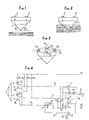
- the prism 1 is of cylindroconic shape with an apex angle of 90 °.
- the upper face of the prism 1 receives a transmitter 2 and a receiver 3, for example of the infrared cell type placed in the median axis of the cone defining the prism, the assembly forming a transmitter-receiver sensor.
- Fig. 1 shows a provision of light rays when the prism 1 is totally in the air.
- the emitted light ray shown in broken lines is reflected by two reflections at 90 °, the corresponding reflected ray, shown in solid line, is then perceived by the receiver 3.
- Fig. 2 shows the arrangement of the light rays when the prism 1 is partly immersed in the liquid 4. In such a case, the emitted light beam is refracted and passes into the liquid 4 so that the receiver 3 no longer receives light.
- the Metrology Service to which is subject, for example, the control of the combined block described in the European patent application 84 401652.7 above requires, at the level of the detection of the liquid, a so-called positive security operation.
- a positive security implies that the non-emission or non-reception of the above light beam can be detected regardless of the origin of the fault (presence of liquid at the detector, transmitter sensor defective receiver, fault in the electronic or electrical part to which the detector is connected ).
- the detector according to the invention comprises a dual sensor formed of a pair of sensors A and B.
- the double sensor is mounted in a prism similar to the prism 1 of FIGS. 1 and 2 and is connected to a suitable electronic circuit.
- Two emitter cells 2 and 2b and two receptor cells 3a and 3b, respectively, similar to the cells 2 and 3 in Fig. 1, are mounted in the same radius at the top of the cone at 180 ° by pair A and B of transceiver sensors at 90 ° to each other. Such an arrangement ensures that there is no interference between the sensors.
- the emitter cells 2 and 2b are respectively connected in parallel between a power supply + V and ground via resistors R1 and R3 and a shunt resistor R.
- the receptor cells 3a and 3 b have their inputs directly connected to the output of the emitter cells 2 a and 2 b and their outputs are connected between the + V supply and the ground O volt via a resistance bridge formed respectively by the resistors R2 , R6 and R4, R5.
- the logic levels of output of the two receptor cells 3a and 3b are preferably set so that a level O corresponds to an absence of liquid and a level 1 to the detection of a presence of liquid, in which case the receptor cells no longer receive light from the emitter cells.
- the outputs of the recipient cells 3a and 3b are then connected by links 4 and 5 to a NAND gate 6 NAND function.
- the two sensors must be at level 1 in order to obtain a level O at the output of the NAND circuit 6 in the case of liquid detection.
- comparators mounted between a reference source and the outputs of the various elements of the sensors.
- Comparators 7 and 8 have one of their inputs connected by links 4 and 5 to the corresponding outputs of the recipient cells 3a and 3b, while the other input of the comparators 7 and 8 is connected to a reference voltage U1.
- a comparator 9 is connected by a link directly to the output 10-11 of the emitter cells 2 and 2b and therefore the entry of the recipient cells 3a and 3b.
- the comparator 9 is further connected by its other input to a reference voltage U2.
- a fourth comparator, referenced 12 is also connected by a linkage 13-11 to the output of the emitter cells 2 and 2b and the other input receives a reference voltage U3.
- the output of the above NAND gate is further connected by a gate 14 to the first input of a second NAND gate 15 whose other input is connected by a link 16 to the common output of the comparators 7, 8 , 9 and 12.
- the output S of the NAND gate 16 corresponds to the output of the entire device.
- the supply links of the device are constituted by the connection + V and the connection O volt to ground.
- Both comparators 7 and 8 compare the voltages at the output of the recipient cells 3a and 3b with respect to the reference voltage U1.
- the voltage + V can not appear on the connection wires 4 or 5 except in the event of a short-circuit of the output or outputs of at least one sensors with the + V of the power supply.
- the voltage on the connecting wires 4 and 5 is then compared with the voltage U1.
- An appropriate setting of U1 (U1 less than or equal to + V) causes an alarm condition at the output of the comparator 7 or 8 corresponding when the voltage on the son 4 or 5 reaches the value U1.
- the assembly of the dual sensor and its associated electronic circuit constitute a positive security level detector.
Abstract
Description
La présente invention concerne un dispositif à capteur double pour la réalisation de détecteurs de niveau.The present invention relates to a dual sensor device for producing level detectors.
Il existe de nombreux cas où il est nécessaire de détecter l'arrivée d'un liquide à un niveau déterminé. Par exemple, dans le block combiné dégazeur, purgeur, bloqueur, récupérateur pour appareils de mesure volumétrique à sécurité renforcée selon la demande de brevet européen 84 401652.7, il existe un détecteur de niveau basé sur le principe d'un flotteur muni d'une ferrite actionnant un contact à lame souple et fournissant ainsi un signal de proximité suivant le niveau du liquide.There are many cases where it is necessary to detect the arrival of a liquid at a certain level. For example, in the combination block degasser, trap, blocker, recuperator for volumetric measuring devices with enhanced security according to the European patent application 84 401652.7, there is a level detector based on the principle of a float equipped with a ferrite actuating a flexible blade contact and thereby providing a proximity signal depending on the level of the liquid.
Le présent détecteur est basé sur un principe totalement différent de type opto-électronique.The present detector is based on a totally different principle of the opto-electronic type.
Conformément à l'invention, le détecteur comprend un prisme à réflexion totale réalisé en une matière transparente, deux capteurs émetteurs récepteurs reliés par paire, d'une part, de manière optique audit prisme et, d'autre part, de manière électrique à un dispositif logique en permettant ainsi de détecter la présence ou l'absence d'un signal reçu par au moins un des récepteurs de la paire de capteurs.According to the invention, the detector comprises a total reflection prism made of a transparent material, two paired transceiver sensors, on the one hand, optically to said prism and, on the other hand, electrically logic device thus making it possible to detect the presence or absence of a signal received by at least one of the receivers of the pair of sensors.
Suivant d'autres caractéristiques de l'invention, le prisme à réflexion totale est réalisé en une matière transparente et présente une forme cylindro-conique d'angle au sommet inférieur de 90° et dont la partie reçoit la paire de capteurs disposés dans l'axe médian du cône perpendiculairement l'un à l'autre. Les récepteurs de la paire de capteurs sont au niveau logique O lorsqu'ils reçoivent une information émise par les émetteurs et au niveau logique 1 dans le cas contraire, le dispositif logique de détection présentant la forme d'une porte NAND à fonction NON-ET.According to other features of the invention, the total reflection prism is made of a transparent material and has a cylindrical-conical shape with a lower apex angle of 90 ° and whose part receives the pair of sensors arranged in the median axis of the cone perpendicular to each other. The receivers of the pair of sensors are at logic level O when they receive information transmitted by the transmitters and at logic level 1 otherwise, the detection logic device having the form of a NAND gate with a NAND function .
Suivant encore une autre particularité de l'invention, les émetteurs et les récepteurs de la paire de capteurs sont chacun constitués par des cellules de type infrarouge, et les sorties des deux émetteurs et les deux récepteurs présentent des liaisons communes respectivement reliées à une première entrée de comparateurs dont la seconde entrée reçoit des tensions de référence. En outre, la sortie des divers comparateurs est reliée en commun à la première entrée d'une seconde porte NAND dont la seconde entrée est reliée à la sortie de la première porte NAND, la sortie de cette seconde porte NAND constituant une sortie du dispositif.According to yet another particularity of the invention, the emitters and receivers of the pair of sensors are each constituted by infrared-type cells, and the outputs of the two emitters and the two receivers have common connections respectively connected to a first input. comparators whose second input receives reference voltages. In addition, the output of the various comparators is connected in common to the first input of a second NAND gate whose second input is connected to the output of the first NAND gate, the output of this second NAND gate constituting an output of the device.
L'invention sera mieux comprise à la lecture de la description ci-après et à l'examen des dessins annexés dans lesquels :
- Les fig. 1 et 2 représentent schématiquement la partie optique d'un détecteur de type connu dans deux positions de fonctionnement ;
- la fig. 3 représente schématiquement la partie optique du détecteur selon l'invention ;
- la fig. 4 est un schéma de principe de l'ensemble du détecteur de niveau selon l'invention.
- Figs. 1 and 2 show schematically the optical part of a known type of detector in two operating positions;
- fig. 3 schematically shows the optical part of the detector according to the invention;
- fig. 4 is a block diagram of the entire level detector according to the invention.
Aux fig. 1 et 2, un prisme à réflexion totale est réalisé en verre ou en une matière plastique transparente de type usuel en optique. Le prisme 1 est de forme cylindroconique à angle au sommet de 90°. La face supérieure du prisme 1 reçoit un émetteur 2 et un récepteur 3, par exemple du type cellule à infrarouge placés dans l'axe médian du cône définissant le prisme, l'ensemble formant un capteur émetteur-récepteur.In figs. 1 and 2, a total reflection prism is made of glass or a transparent plastic material of the usual type in optics. The prism 1 is of cylindroconic shape with an apex angle of 90 °. The upper face of the prism 1 receives a
La fig. 1 montre une disposition de rayons lumineux lorsque le prisme 1 est totalement dans l'air. Le rayon lumineux émis représenté en traits interrompus est réfléchi par deux réflexions à 90°, le rayon reflété correspondant, représenté en trait continu, est alors perçu par le récepteur 3.Fig. 1 shows a provision of light rays when the prism 1 is totally in the air. The emitted light ray shown in broken lines is reflected by two reflections at 90 °, the corresponding reflected ray, shown in solid line, is then perceived by the
La fig. 2 montre la disposition des rayons lumineux lorsque le prisme 1 est en partie immergé dans le liquide 4. Dans un tel cas, le rayon lumineux émis est réfracté et passe dans le liquide 4 de sorte que le récepteur 3 ne reçoit plus de lumière.Fig. 2 shows the arrangement of the light rays when the prism 1 is partly immersed in the liquid 4. In such a case, the emitted light beam is refracted and passes into the liquid 4 so that the
Un tel système est connue en soi dans la technique de l'optique comme dans l'industrie et n'est pas directement utilisable en métrologie.Such a system is known per se in the art of optics as in industry and is not directly usable in metrology.
En effet, le Service de la Métrologie auquel est assujetti, par exemple, le contrôle du bloc combiné décrit dans la demande de brevet européen 84 401652.7 ci-dessus exige, au niveau de la détection du liquide, un fonctionnement dit à sécurité positive. Selon le Service de la Métrologie, une telle sécurité positive implique que la non-émission ou la non-réception du rayon lumineux ci-dessus puisse être détectée quelle que soit l'origine du défaut (présence de liquide au niveau du détecteur, capteur émetteur-récepteur défectueux, défaut dans la partie électronique ou électrique à laquelle est relié le détecteur ...).Indeed, the Metrology Service to which is subject, for example, the control of the combined block described in the European patent application 84 401652.7 above requires, at the level of the detection of the liquid, a so-called positive security operation. According to the Metrology Service, such a positive security implies that the non-emission or non-reception of the above light beam can be detected regardless of the origin of the fault (presence of liquid at the detector, transmitter sensor defective receiver, fault in the electronic or electrical part to which the detector is connected ...).
Afin d'assurer une telle sécurité positive et, comme on le voit aux fig. 3 et 4, le détecteur selon l'invention comprend un capteur double formé d'une paire de capteurs A et B. Le capteur double est monté dans un prisme analogue au prisme 1 des fig. 1 et 2 et est relié à un circuit électronique approprié.In order to ensure such a positive security and, as seen in figs. 3 and 4, the detector according to the invention comprises a dual sensor formed of a pair of sensors A and B. The double sensor is mounted in a prism similar to the prism 1 of FIGS. 1 and 2 and is connected to a suitable electronic circuit.
Deux cellules émettrices 2a et 2b et deux cellules réceptrices 3a et 3b respectivement semblables aux cellules 2 et 3 de la fig. 1, sont montées dans un même rayon au sommet du cône à 180° par paire A et B de capteurs émetteurs-récepteurs à 90° l'un de l'autre. Un tel montage permet d'assurer qu'il n'existe aucune interférence entre les capteurs.Two
A la fig. 4, des cellules émettrices 2a et 2b sont respectivement montées en parallèle entre une alimentation +V et la terre par l'intermédiaire de résistances R₁ et R₃ et d'une résistance de shunt R. De même, les cellules réceptrices 3a et 3b ont leurs entrées directement reliées à la sortie des cellules émettrices 2a et 2b et leurs sorties sont reliées entre l'alimentation +V et la masse O volt par l'intermédiaire d'un pont de résistance constitué respectivement par les résistances R₂, R₆ et R₄, R₅.In fig. 4, the
Conformément à l'invention, les niveaux logiques de sortie des deux cellules réceptrices 3a et 3b sont, de préférence, établis de telle manière qu'un niveau O correspond à une absence de liquide et un niveau 1 à la détection d'une présence de liquide, cas dans lequel les cellules réceptrices ne reçoivent plus de lumière issue des cellules émettrices.According to the invention, the logic levels of output of the two
Les sorties des cellules réceptrices 3a et 3b sont alors reliées par des liaisons 4 et 5 à une porte NAND 6 à fonction NON-ET. Ainsi, les deux capteurs doivent être au niveau 1 afin d'obtenir un niveau O à la sortie du circuit NAND 6 dans le cas de la détection de liquide.The outputs of the
De manière à assurer des fonctions complémentaires dont il sera question plus loin, on prévoit en outre des comparateurs montés entre une source de référence et les sorties des divers élements des capteurs.In order to provide complementary functions which will be discussed later, there are further provided comparators mounted between a reference source and the outputs of the various elements of the sensors.
Des comparateurs 7 et 8 présentent ainsi une de leurs entrées reliées par des liaisons 4 et 5 aux sorties correspondantes des cellules réceptrices 3a et 3b, tandis que l'autre entrée des comparateurs 7 et 8 est reliée à une tension de référence U₁. De même un comparateur 9 est relié par une liaison 10-11 directement à la sortie des cellules émettrices 2a et 2b et donc à l'entrée des cellules réceptrices 3a et 3b. Le comparateur 9 est en outre relié par son autre entrée à une tension de référence U₂. Un quatrième comparateur, référencé 12, est également relié par une liaison 13-11 à la sortie des cellules émettrices 2a et 2b et son autre entrée reçoit une tension de référence U₃.Comparators 7 and 8 and have one of their inputs connected by
La sortie de la porte NAND ci-dessus est, en outre, reliée par une porte 14 à la première entrée d'une seconde porte NAND 15 dont l'autre entrée est reliée par une liaison 16 à la sortie commune des comparateurs 7, 8, 9 et 12. La sortie S de la porte NAND 16 correspond à la sortie de l'ensemble du dispositif.The output of the above NAND gate is further connected by a gate 14 to the first input of a second NAND gate 15 whose other input is connected by a
La disposition qui précède permet de détecter les divers défauts définis ci-après.The foregoing arrangement makes it possible to detect the various defects defined below.
Les liaisons d'alimentation du dispositif sont constituées par la liaison +V et la liaison O volt à la terre.The supply links of the device are constituted by the connection + V and the connection O volt to ground.
Si on considère le courant circulant dans les émetteurs-récepteurs du capteur double décrit plus haut, on voit que, par l'intermédiaire des liaisons d'alimentation, ce courant circule dans le fil de liaison 11 et passe à la terre à travers la résistance R de shunt soit Ic l'intensité de ce courant. La tension RIc au point commun C des fils de liaison 10, 11 et 13 est alors appliquée aux deux comparateurs 9 et 12.If we consider the current flowing in the transceivers of the double sensor described above, we see that, through the supply links, this current flows in the connecting wire 11 and goes to earth through the resistor R shunt is I c the intensity of this current. The voltage RI c at the common point C of the connecting
En cas d'incidents de coupure, Ic diminue et un niveau bas de la tension RIc détecté par le comparateur 9 indique un état d'alarme correspondant à RIc inférieur à U₂ (niveau bas). Cet état d'alarme apparaît à la sortie du comparateur 9.In case of failure of cut, I c decreases and a low level of the voltage RI c detected by the comparator 9 indicates an alarm state corresponding to RI c less than U₂ (low level). This alarm state appears at the output of the comparator 9.
Lorsqu'il existe un court-circuit entre le +V d'alimentation et la masse, ou encore si un des composants du capteur est défectueux, l'intensité dans le circuit augmente. Ainsi, lorsque IC dépasse une certaine valeur, un niveau supérieur de cette intensité indique un état d'alarme correspondant à RIc supérieur à U₃ (niveau haut). Cet état d'alarme apparaît à la sortie du comparateur 12.When there is a short circuit between the + V supply and ground, or if one of the components of the sensor is defective, the intensity in the circuit increases. Thus, when I C exceeds a certain value, a higher level of this intensity indicates an alarm state corresponding to RI c greater than U₃ (high level). This alarm state appears at the output of the
Le circuit NAND référencé 6 qui est ainsi relié par les liaisons 4, 5 aux sorties des cellules réceptrices 3a et 3b détectent un ou des niveaux logiques O dans chaque cas où il y a coupure d'au moins une des liaisons d'un ou des capteurs et/ou une absence de liquide et/ou encore un court-circuit à la masse au O volt.The NAND circuit referenced 6, which is thus connected by the
Les deux comparateurs 7 et 8 comparent les tensions à la sortie des cellules réceptrices 3a et 3b par rapport à la tension de référence U₁.Both comparators 7 and 8 compare the voltages at the output of the
Les capteurs étant associés respectivement aux diviseurs de tension R2 - R6 et R4 - R5, la tension +V ne peut pas apparaître sur les fils de liaison 4 ou 5 sauf en cas de court-circuit de la ou des sorties d'au moins un des capteurs avec le +V de l'alimentation. La tension sur les fils de liaison 4 et 5 est alors comparée avec la tension U₁. Un réglage approprié de U₁ (U₁ inférieur ou égal à +V) provoque un état d'alarme à la sortie du comparateur 7 ou 8 correspondant lorque la tension sur les fils 4 ou 5 atteint la valeur U₁.Since the sensors are associated respectively with the voltage dividers R2-R6 and R4-R5, the voltage + V can not appear on the
Les divers états d'alarme mentionnés précédemment apparaissent en S à la sortie de la porte NAND 15.The various alarm states mentioned above appear in S at the output of the NAND gate 15.
Comme on le voit, l'ensemble du capteur double et de son circuit électronique associés constitue un détecteur de niveau à sécurité positive.As can be seen, the assembly of the dual sensor and its associated electronic circuit constitute a positive security level detector.
Bien que cela n'ait pas été représenté, il est possible de réaliser le capteur avec des liaisons à fibres optiques, les divers émetteurs et récepteurs se trouvant à distance d'une zone supposée dangereuse.Although this has not been shown, it is possible to realize the sensor with fiber optic links, the various transmitters and receivers located at a distance from a supposedly dangerous area.
L'invention n'est pas limitée aux modes de réalisation représentés et décrits en détail car diverses modifications peuvent y être apportées sans sortir de son cadre.The invention is not limited to the embodiments shown and described in detail since various modifications can be made without departing from its scope.
Claims (8)
Priority Applications (4)
| Application Number | Priority Date | Filing Date | Title |
|---|---|---|---|
| AT86400911T ATE44094T1 (en) | 1986-04-24 | 1986-04-24 | ELECTRONIC OPTICAL LEVEL DETECTOR WITH DOUBLE TRANSDUCER. |
| DE198686400911T DE245563T1 (en) | 1986-04-24 | 1986-04-24 | ELECTROOPTIC LEVEL DETECTOR WITH DOUBLE MEASURING VALUE. |
| EP86400911A EP0245563B1 (en) | 1986-04-24 | 1986-04-24 | Optico-electronic level detector with double pick-up elements |
| DE8686400911T DE3663999D1 (en) | 1986-04-24 | 1986-04-24 | Optico-electronic level detector with double pick-up elements |
Applications Claiming Priority (1)
| Application Number | Priority Date | Filing Date | Title |
|---|---|---|---|
| EP86400911A EP0245563B1 (en) | 1986-04-24 | 1986-04-24 | Optico-electronic level detector with double pick-up elements |
Publications (2)
| Publication Number | Publication Date |
|---|---|
| EP0245563A1 true EP0245563A1 (en) | 1987-11-19 |
| EP0245563B1 EP0245563B1 (en) | 1989-06-14 |
Family
ID=8196298
Family Applications (1)
| Application Number | Title | Priority Date | Filing Date |
|---|---|---|---|
| EP86400911A Expired EP0245563B1 (en) | 1986-04-24 | 1986-04-24 | Optico-electronic level detector with double pick-up elements |
Country Status (3)
| Country | Link |
|---|---|
| EP (1) | EP0245563B1 (en) |
| AT (1) | ATE44094T1 (en) |
| DE (2) | DE3663999D1 (en) |
Cited By (3)
| Publication number | Priority date | Publication date | Assignee | Title |
|---|---|---|---|---|
| EP0460432A2 (en) * | 1990-05-29 | 1991-12-11 | AC & R COMPONENTS, INC. | Oil level control system |
| FR2704647A1 (en) * | 1993-04-30 | 1994-11-04 | Luro Sarl Ets | Device for high-precision measurement and self-monitoring of the height of a liquid in an enclosure |
| CN109239514A (en) * | 2018-08-03 | 2019-01-18 | 重庆川仪自动化股份有限公司 | A kind of liquidometer short circuit sensor, open detection circuit |
Families Citing this family (2)
| Publication number | Priority date | Publication date | Assignee | Title |
|---|---|---|---|---|
| DE4102106C2 (en) * | 1991-01-25 | 1994-01-13 | Honeywell Regelsysteme Gmbh | Level sensor |
| CN110361067B (en) * | 2019-07-12 | 2021-01-01 | 彩虹(合肥)液晶玻璃有限公司 | Liquid level measuring device |
Citations (6)
| Publication number | Priority date | Publication date | Assignee | Title |
|---|---|---|---|---|
| CH404224A (en) * | 1962-12-19 | 1965-12-15 | Foerderung Forschung Gmbh | Liquid monitoring detector |
| FR2238919A2 (en) * | 1973-07-26 | 1975-02-21 | Illinois Tool Works | Optical indicator for liquid level in tank - involves transparent blocks with V-shaped bottoms with lamp |
| GB1518492A (en) * | 1977-02-04 | 1978-07-19 | Ford Motor Co | Liquid level warning device |
| CH615995A5 (en) * | 1977-05-10 | 1980-02-29 | Benno Perren | Electrooptic device for detecting the presence of liquid. |
| DE2927449A1 (en) * | 1979-07-06 | 1981-01-15 | Siemens Ag | Opto-electronic fluid detector - has light emitting diode source and photodiode receivers of light reflected from fluid surface |
| DE3533523A1 (en) * | 1984-09-22 | 1986-04-17 | Sharp K.K., Osaka | FAILURE DETECTOR |
-
1986
- 1986-04-24 DE DE8686400911T patent/DE3663999D1/en not_active Expired
- 1986-04-24 EP EP86400911A patent/EP0245563B1/en not_active Expired
- 1986-04-24 AT AT86400911T patent/ATE44094T1/en not_active IP Right Cessation
- 1986-04-24 DE DE198686400911T patent/DE245563T1/en active Pending
Patent Citations (6)
| Publication number | Priority date | Publication date | Assignee | Title |
|---|---|---|---|---|
| CH404224A (en) * | 1962-12-19 | 1965-12-15 | Foerderung Forschung Gmbh | Liquid monitoring detector |
| FR2238919A2 (en) * | 1973-07-26 | 1975-02-21 | Illinois Tool Works | Optical indicator for liquid level in tank - involves transparent blocks with V-shaped bottoms with lamp |
| GB1518492A (en) * | 1977-02-04 | 1978-07-19 | Ford Motor Co | Liquid level warning device |
| CH615995A5 (en) * | 1977-05-10 | 1980-02-29 | Benno Perren | Electrooptic device for detecting the presence of liquid. |
| DE2927449A1 (en) * | 1979-07-06 | 1981-01-15 | Siemens Ag | Opto-electronic fluid detector - has light emitting diode source and photodiode receivers of light reflected from fluid surface |
| DE3533523A1 (en) * | 1984-09-22 | 1986-04-17 | Sharp K.K., Osaka | FAILURE DETECTOR |
Non-Patent Citations (2)
| Title |
|---|
| EDN MAGAZINE; vol. 26, 14 Octobre 1981, page 379, Boston, Mass., US; E.J. WHITESELL: "Schmitt triggers isolate coax faults" * |
| PRODUCT ENGINEERING, vol. 39, no. 20, 23 septembre 1968, pages 81,82: "Optical switch uses reflection to monitor the level of liquid" * |
Cited By (4)
| Publication number | Priority date | Publication date | Assignee | Title |
|---|---|---|---|---|
| EP0460432A2 (en) * | 1990-05-29 | 1991-12-11 | AC & R COMPONENTS, INC. | Oil level control system |
| EP0460432A3 (en) * | 1990-05-29 | 1992-04-15 | Ac & R Components, Inc. | Oil level control system |
| FR2704647A1 (en) * | 1993-04-30 | 1994-11-04 | Luro Sarl Ets | Device for high-precision measurement and self-monitoring of the height of a liquid in an enclosure |
| CN109239514A (en) * | 2018-08-03 | 2019-01-18 | 重庆川仪自动化股份有限公司 | A kind of liquidometer short circuit sensor, open detection circuit |
Also Published As
| Publication number | Publication date |
|---|---|
| DE245563T1 (en) | 1988-03-17 |
| DE3663999D1 (en) | 1989-07-20 |
| EP0245563B1 (en) | 1989-06-14 |
| ATE44094T1 (en) | 1989-06-15 |
Similar Documents
| Publication | Publication Date | Title |
|---|---|---|
| US4803470A (en) | Substance detector device | |
| EP0021945B1 (en) | Monomode fibre-optic hydrophone functioning by the elasto-optic effect | |
| US3877821A (en) | Apparatus for detecting flaws using an array of photo sensitive devices | |
| US6455854B1 (en) | Infrared radiation detector for monitoring the presence of alkanes | |
| EP0245563B1 (en) | Optico-electronic level detector with double pick-up elements | |
| US3664752A (en) | Photoelectric measuring devices | |
| FR2722291A1 (en) | Reflectometer esp. for detecting raindrops on windscreen of vehicle | |
| EP0055319B1 (en) | Smoke detector of the light diffusion type with self-checking | |
| FR2478141A1 (en) | MULTI-SENSOR APPARATUS FOR DETECTION OF DETACHED WIRES | |
| FR2633055A2 (en) | IMPROVEMENTS IN CIRCUIT TESTERS | |
| FR2910641A1 (en) | DEVICE AND METHOD FOR TESTING A RAIN SENSOR | |
| EP3973256A1 (en) | Fibre-optic acoustic sensor and associated measurement system, vehicle and measurement method | |
| EP2069813B1 (en) | Method and device for characterising an electric signal propagating through a sample | |
| EP0497649A1 (en) | Method and device for testing the surface condition of a light transmitting optical element | |
| FR2666163A1 (en) | Opto-electronic device for detecting smoke or gas in suspension in air | |
| JPH08184556A (en) | Optical gas detector | |
| FR2888323A1 (en) | METHOD FOR EVALUATING A MIXTURE OF PETROLEUM PRODUCTS AND BIOFUELS | |
| JPH0827293B2 (en) | Liquid sensor | |
| FR2784456A1 (en) | Device for measuring distances particularly aircraft door clearances measures intensity of light beam passing through polarizer, magneto-optical film and analyzer in presence of adjacent magnetic field | |
| EP2132522A2 (en) | Optical metrology system | |
| FR2478815A1 (en) | METHOD AND APPARATUS FOR EVALUATING VISIBILITY | |
| FR2567651A1 (en) | Equipment for measuring the speed of a projectile by interferometry using a laser beam propagated by a single optical waveguide | |
| EP4264936A1 (en) | Lighting device and imaging device comprising such a lighting device | |
| BE864281Q (en) | DEVICE FOR THE CONTROL OF DOCUMENTS | |
| FR2505045A1 (en) | Fibre=optic cable fracture location determn. circuit - uses clock to measure propagation time difference for two laser diodes emitting different wavelengths |
Legal Events
| Date | Code | Title | Description |
|---|---|---|---|
| PUAI | Public reference made under article 153(3) epc to a published international application that has entered the european phase |
Free format text: ORIGINAL CODE: 0009012 |
|
| 17P | Request for examination filed |
Effective date: 19860502 |
|
| AK | Designated contracting states |
Kind code of ref document: A1 Designated state(s): AT BE CH DE FR GB IT LI LU NL SE |
|
| ITCL | It: translation for ep claims filed |
Representative=s name: STUDIO ING. ALFREDO RAIMONDI |
|
| TCNL | Nl: translation of patent claims filed | ||
| TCAT | At: translation of patent claims filed | ||
| DET | De: translation of patent claims | ||
| 17Q | First examination report despatched |
Effective date: 19880203 |
|
| GRAA | (expected) grant |
Free format text: ORIGINAL CODE: 0009210 |
|
| AK | Designated contracting states |
Kind code of ref document: B1 Designated state(s): AT BE CH DE FR GB IT LI LU NL SE |
|
| REF | Corresponds to: |
Ref document number: 44094 Country of ref document: AT Date of ref document: 19890615 Kind code of ref document: T |
|
| REF | Corresponds to: |
Ref document number: 3663999 Country of ref document: DE Date of ref document: 19890720 |
|
| ITF | It: translation for a ep patent filed |
Owner name: STUDIO ING. ALFREDO RAIMONDI |
|
| GBT | Gb: translation of ep patent filed (gb section 77(6)(a)/1977) | ||
| PLBE | No opposition filed within time limit |
Free format text: ORIGINAL CODE: 0009261 |
|
| STAA | Information on the status of an ep patent application or granted ep patent |
Free format text: STATUS: NO OPPOSITION FILED WITHIN TIME LIMIT |
|
| 26N | No opposition filed | ||
| ITTA | It: last paid annual fee | ||
| PGFP | Annual fee paid to national office [announced via postgrant information from national office to epo] |
Ref country code: FR Payment date: 19940307 Year of fee payment: 9 |
|
| PGFP | Annual fee paid to national office [announced via postgrant information from national office to epo] |
Ref country code: GB Payment date: 19940325 Year of fee payment: 9 |
|
| PGFP | Annual fee paid to national office [announced via postgrant information from national office to epo] |
Ref country code: CH Payment date: 19940328 Year of fee payment: 9 |
|
| PGFP | Annual fee paid to national office [announced via postgrant information from national office to epo] |
Ref country code: LU Payment date: 19940331 Year of fee payment: 9 Ref country code: BE Payment date: 19940331 Year of fee payment: 9 |
|
| PGFP | Annual fee paid to national office [announced via postgrant information from national office to epo] |
Ref country code: AT Payment date: 19940407 Year of fee payment: 9 |
|
| PGFP | Annual fee paid to national office [announced via postgrant information from national office to epo] |
Ref country code: SE Payment date: 19940418 Year of fee payment: 9 |
|
| PGFP | Annual fee paid to national office [announced via postgrant information from national office to epo] |
Ref country code: NL Payment date: 19940430 Year of fee payment: 9 |
|
| PGFP | Annual fee paid to national office [announced via postgrant information from national office to epo] |
Ref country code: DE Payment date: 19940505 Year of fee payment: 9 |
|
| EPTA | Lu: last paid annual fee | ||
| EAL | Se: european patent in force in sweden |
Ref document number: 86400911.3 |
|
| PG25 | Lapsed in a contracting state [announced via postgrant information from national office to epo] |
Ref country code: LU Free format text: LAPSE BECAUSE OF NON-PAYMENT OF DUE FEES Effective date: 19950424 Ref country code: GB Effective date: 19950424 Ref country code: AT Effective date: 19950424 |
|
| PG25 | Lapsed in a contracting state [announced via postgrant information from national office to epo] |
Ref country code: SE Effective date: 19950425 |
|
| PG25 | Lapsed in a contracting state [announced via postgrant information from national office to epo] |
Ref country code: LI Effective date: 19950430 Ref country code: CH Effective date: 19950430 Ref country code: BE Effective date: 19950430 |
|
| BERE | Be: lapsed |
Owner name: EQUIPEMENT INDUSTRIEL NORMAND Effective date: 19950430 |
|
| PG25 | Lapsed in a contracting state [announced via postgrant information from national office to epo] |
Ref country code: NL Effective date: 19951101 |
|
| REG | Reference to a national code |
Ref country code: CH Ref legal event code: PL |
|
| GBPC | Gb: european patent ceased through non-payment of renewal fee |
Effective date: 19950424 |
|
| PG25 | Lapsed in a contracting state [announced via postgrant information from national office to epo] |
Ref country code: FR Effective date: 19951229 |
|
| NLV4 | Nl: lapsed or anulled due to non-payment of the annual fee |
Effective date: 19951101 |
|
| PG25 | Lapsed in a contracting state [announced via postgrant information from national office to epo] |
Ref country code: DE Effective date: 19960103 |
|
| EUG | Se: european patent has lapsed |
Ref document number: 86400911.3 |
|
| REG | Reference to a national code |
Ref country code: FR Ref legal event code: ST |
|
| PG25 | Lapsed in a contracting state [announced via postgrant information from national office to epo] |
Ref country code: IT Free format text: LAPSE BECAUSE OF NON-PAYMENT OF DUE FEES;WARNING: LAPSES OF ITALIAN PATENTS WITH EFFECTIVE DATE BEFORE 2007 MAY HAVE OCCURRED AT ANY TIME BEFORE 2007. THE CORRECT EFFECTIVE DATE MAY BE DIFFERENT FROM THE ONE RECORDED. Effective date: 20050424 |