EP0245562A2 - Bildstabilisation für eine Raumfahrzeugkamera - Google Patents
Bildstabilisation für eine Raumfahrzeugkamera Download PDFInfo
- Publication number
- EP0245562A2 EP0245562A2 EP86309780A EP86309780A EP0245562A2 EP 0245562 A2 EP0245562 A2 EP 0245562A2 EP 86309780 A EP86309780 A EP 86309780A EP 86309780 A EP86309780 A EP 86309780A EP 0245562 A2 EP0245562 A2 EP 0245562A2
- Authority
- EP
- European Patent Office
- Prior art keywords
- spacecraft
- compensation signal
- mirror
- camera
- external
- Prior art date
- Legal status (The legal status is an assumption and is not a legal conclusion. Google has not performed a legal analysis and makes no representation as to the accuracy of the status listed.)
- Granted
Links
- 230000007774 longterm Effects 0.000 claims abstract description 11
- 238000005259 measurement Methods 0.000 claims abstract description 10
- 230000000694 effects Effects 0.000 claims description 18
- 238000003384 imaging method Methods 0.000 claims description 17
- 238000000926 separation method Methods 0.000 claims description 5
- 238000012360 testing method Methods 0.000 claims description 4
- 238000000034 method Methods 0.000 claims description 3
- 230000003213 activating effect Effects 0.000 claims 1
- 230000000737 periodic effect Effects 0.000 abstract description 9
- 238000012937 correction Methods 0.000 description 8
- 230000003993 interaction Effects 0.000 description 2
- 230000005855 radiation Effects 0.000 description 2
- 230000032683 aging Effects 0.000 description 1
- 230000003679 aging effect Effects 0.000 description 1
- 230000003466 anti-cipated effect Effects 0.000 description 1
- 238000004364 calculation method Methods 0.000 description 1
- 230000015556 catabolic process Effects 0.000 description 1
- 238000006731 degradation reaction Methods 0.000 description 1
- 238000010586 diagram Methods 0.000 description 1
- 238000006073 displacement reaction Methods 0.000 description 1
- 230000007613 environmental effect Effects 0.000 description 1
- 238000009499 grossing Methods 0.000 description 1
- 238000003780 insertion Methods 0.000 description 1
- 230000037431 insertion Effects 0.000 description 1
- 238000012544 monitoring process Methods 0.000 description 1
- 230000003287 optical effect Effects 0.000 description 1
- 238000011160 research Methods 0.000 description 1
- 230000001932 seasonal effect Effects 0.000 description 1
- 230000035945 sensitivity Effects 0.000 description 1
- 230000000087 stabilizing effect Effects 0.000 description 1
- 238000012546 transfer Methods 0.000 description 1
- 230000001052 transient effect Effects 0.000 description 1
Images


Classifications
-
- G—PHYSICS
- G01—MEASURING; TESTING
- G01C—MEASURING DISTANCES, LEVELS OR BEARINGS; SURVEYING; NAVIGATION; GYROSCOPIC INSTRUMENTS; PHOTOGRAMMETRY OR VIDEOGRAMMETRY
- G01C21/00—Navigation; Navigational instruments not provided for in groups G01C1/00 - G01C19/00
- G01C21/20—Instruments for performing navigational calculations
Definitions
- This invention pertains to the field of maintaining within a preselected limit the angular separation of corresponding pixels of repeated images of the same selected imaging area of a spacecraft camera.
- U.S. patent 3,952,151 discloses a method and apparatus for stabilizing an image produced by e.g., a camera on board a satellite, by sensing the instantaneous attitude displacement of the satellite and using these signals to adjust the image-generating beam at the ground station.
- the instant invention differs from the reference system in that: 1) It is a closed-loop system whereas the reference system is an open-loop system. 2) It does not require the gyroscopes needed by the reference system. Gyroscopes are heavy, consume much power, are not very accurate, have a stability and drift problem, and normally require an onboard star tracker for calibration. 3) It corrects for orbit and thermal variations as well as attitude control variations, whereas the reference system corrects for just attitude control variations. 5) It uses the camera 1, 2 itself to self-correct for errors whereas the reference system does not.
- One or more cameras (1, 2) onboard a spacecraft generates images of scenes external to the spacecraft, such as on the earth. Long term motion pertubations on the orbit and attitude of the spacecraft are determined as part of operations ground equipment (OGE). This information, in the form of coefficents (K, A), is periodically fed to an on-board computer (38), which, in response thereto, generates an image registration compensation signal (60). Signal (60) is sent to the servo control loops (84, 88, 94, 98) of the camera mirrors (33, 32).
- OGE operations ground equipment
- Image registration is the process of limiting the error in the angular separation of corresponding pixels (with respect to each other) of repeated images of the same selected imaging area (frame) to within a specified preselected limit (for an example, see Table 1).
- the images are taken by one or more cameras 1, 2 onboard a spacecraft.
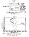
- Fig. 1 one of the geosynchronous GOES IJKLM meteorological satellites sponsored by NOAA (National Oceanic and Atmospheric Administration) and contracted for by NASA (National Aeronautics and Space Administration).
- the items shown on Fig. 1 include solar array 11, x-ray sensor 12, magnetometor 13, S-band transmit antenna 14, search and rescue antenna 15, UHF antenna 16, telemetry and command antenna 18, earth sensors 19, S-band receive antenna 20, solar sail 24, and two cameras: imager 1 and sounder 2.
- Imager 1 comprises cooler 17, aperture 23, and mirror 33.
- Sounder 2 comprises cooler 21, aperture 22, and mirror 32.
- the mirrors 33, 32 are each mounted on a two-axis gimbal which selectively positions the mirror 33, 32 with respect to orthogonal x and y axes at a very fast step-scan rate of many successive positions per second.
- the ostensibly common x axis can also be referred to as the roll, north/south, or elevation axis.
- the y axis for each mirror 33, 32 can also be referred to as the pitch, east/west, or azimuth axis.
- Imager 1 provides multispectral radiometric imaging of the earth's surface, which can be useful, for example, in measuring transverse cloud velocity.
- Imager 1 has five channels, four infrared and one visible; its two-axis gimbaled scanning mirror 33 sweeps an eight kilometer longitudinal swath along an east/west path on the earth, providing co-registered data of the viewed scene from all channels simultaneously. Position and size of the area scanned are controlled by command from scan logic 83, 87 (Fig. 8).
- the field of view of imager 1 is divided into a set of parallel scan lines each comprising many pixels.
- the pixel size (on the earth) is as small as 1 km by 1 km for one of the channels.
- a scan frame (comprising many scan lines) is that subset of the total possible field of view that is commanded to be scanned.
- the scan frame is scanned in an amount of time known as the "correlation time", which is 22 minutes for a whole earth scan, less for an "area scan” (portion of the earth).
- Radiometric calibration is provided by periodic mirror 33 slews to space and to an internal blackbody target.
- Sounder 2 measures moisture content and temperature within the earth's atmosphere on a pixel-by-pixel basis.
- Sounder 2 comprises a 19 channel (18 infrared and 1 visible) discrete filter wheel radiometer; its two-axis gimbaled scanning mirror 32 step-scans a 40 kilometer longitudinal swath across an east/west path in 10 kilometer increments.
- the nominal pixel size (on the earth) is 10 km by 10 km.
- a scan frame (comprising many scan lines) is scanned in an amount of time known as the correlation time.
- Passive radiation cooler 21 controls the filter wheel assembly temperature. This allows operation at lower temperature for increased sensitivity. Radiometric calibration is provided by periodic mirror 32 slews to space and to an internal blackbody target.
- Imager 1 and sounder 2 operate independently and simultaneously over a period of time known as an imaging or sounding "interval".
- the interval is specified to be at least 85 minutes and can be as much as 12 hours.
- several frames are scanned and several images made.
- the instruments 1, 2 are turned off and the spacecraft may enter the housekeeping mode, e.g., to fire thrusters for purposes of attitude control or momentum dumping.
- the total pixel registration error is the sum of the N-S and E-W separation angles between centroids of corresponding pixels for successive images within an imaging or sounding interval. Needless to say, the lower the pixel registration error, the higher the quality of images emanating from instruments 1, 2.
- the present invention achieves the GOES IJKLM image registration accuracy requirements (shown in Table 1) with margin.
- the present invention eliminates deterministic long-term motion effects on image registration in a closed-loop real-time fashion using an onboard image motion compensation system (IMCS), which operates directly on the mirrors 33, 32, and a model of orbital and attitude motion located on the earth.
- IMCS onboard image motion compensation system
- the invention is transparent to the user.
- the mirror 33, 32 normal motion is slow enough for the compensation system's computer 38 to apply effective E-W (azimuth) and N-S (elevation) corrections simultaneously.
- the long-term motion effects compensated by the present invention include orbital inclination and orbital eccentricity (orbital effects); and yaw error, structural thermal distortion, and earth sensor 19 thermal variation (attitude effects).
- Figure 2 shows scan lines, with respect to a Mercator projection of the earth, traced by imager 1 or sounder 2 with and without pixel shift due to orbit/attitude perturbations.
- the shift has been exaggerated in the Figure for purposes of illustration. It is desired that the scan lines be horizontal.
- mirrors 33, 32 follow arcuate paths to accomplish this, due to the earth's curvature.
- Another consequence of the earth's curvature is that the sizes of the pixels on the earth vary.
- the scan line with pixel shift depicted in Fig. 2 is skewed in both elevation and azimuth, although the azimuth skew can't be detected just by looking at Fig. 2 since the normal motion of the scan line is horizontal.
- the onboard compensation involves a stepped sequence of incremental adjustments ( ⁇ AZ, ⁇ EL) that are applied to the azimuth and elevation servo control loops 88, 98, 84, 94 (Fig. 8) while the mirrors 33, 32 are generating scan lines.
- the correction signal 60 is applied in a direction opposite that of the undesired offset of the mirror 33, 32.
- the correction ( ⁇ AZ, ⁇ EL) is applied in an east-south direction to compensate opposing motion (west-north) of the mirror 33, 32.
- This correction signal 60 is updated every 64 milliseconds along the scan line.
- the compensated scan line is seen by the user, it appears very similar to a scan line with no pixel shift.
- Points 62 demarcate the beginning and end of each 64 msec compensation period. During each such period, computer 38 calculates a ⁇ AZ, ⁇ EL correction signal 60. Signal 60 is converted to analog form and low pass filtered by filters 81, 85, 91, 95, resulting in a smoothing of the compensation signal into the dashed form 63 depicted in Fig. 7. This smoothed signal 63 is then fed to the servo loops 84, 88, 94, 98, in four independent components 63A, B, C, D corresponding to the two axes x, y of each of the two instruments 1, 2.
- each low-pass filter 81, 85, 91, 95 is selected such that the error in each smooth segment 63(n) is about 10% of the input step size ⁇ EL(n), where n is a positive integer. n ranges from 1 through 14 to cover the entire scan line. In Fig. 7, n is shown ranging from 1 through 9.
- the maximum residual error after compensation is less than 2 microradians.
- the residual error is even smaller because of the slower stepping rate of mirror 32 compared with mirror 33.
- FIG. 3 The spacecraft ground track (declination) due to a 0.1° inclination is shown in Figure 3.
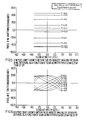
- Figures 4 through 6 show the effect of the 0.1° inclination on pixel shift at two elevation angles (0°, 8°) at various times T (in hours) along the spacecraft ground track shown in Figure 3.
- the east-west pixel shift for 0° elevation is not shown because it is zero.
- 8° is considered an extreme elevation angle, because when the instrument 1, 2 is pointed at the earth, its maximum elevation angle is 8.7° in either direction, for a total elevation range of 17.4° (when the instrument 1, 2 is pointing at stars, its maximum elevation range is 21°).
- FIGs. 4-6 Only a single 6-hour track is shown in Figs. 4-6 because the remaining 6-hour tracks are mirror images of the illustrated 6-hour track about the meridian or the equator. In Figs. 4-6, negative and positive indices after the symbol T indicate shifts at the beginning and end of the 85 minute imaging or sounding interval, respectively.
- the constant E-W shift shown in Figure 5 can be corrected relatively simply, by insertion of a fixed bias into signal 60 at the beginning of each scan line. More complicated shifts, such as the N-S shifts of Figs. 4 and 6, are corrected as shown in Figure 7, by stepping along the scan line at the rate of once every 64 msec (once per 1.25° for imager 1).
- FIG. 8 shows the hardware comprising the IMCS portion of the invention.
- AOCE attitude and orbit control electronics
- processor 38 resides on board the spacecraft; provides the azimuth and elevation corrections 60 to imager 1 and sounder 2 in four independent components 60 A, B, C, D corresponding to the two axes x, y of each of the two instruments 1, 2; and synchronizes the signal 60 magnitude with real-time information 99 indicating the beginning and end of each scan line, the direction of each scan line, the position (AZ, EL) of each mirror 33, 32, and the operating mode of each camera 1, 2.
- the azimuth corrections 60B, 60D and elevation corrections 60A, 60C are each a function of the mirror 33, 32 position (AZ, EL); a set of orbit/attitude compensation coefficients K, A; and synchronization data 99.
- Coefficients K, A are updated to processor 38 daily by command unit 39 associated with a ground portion of an image navigation system.
- a suitable image navigation system is more fully described in a commonly assigned U.S. patent application being filed concurrently herewith, entitled, "Satellite Camera Image Navigation".
- the daily uplinked coefficients K, A are: seven orbital coefficients K (six orbital elements and one epoch time (beginning of a particular orbit/attitude variation)); and 25 attitude coefficients A (four for each of roll, pitch, and yaw of imager 1 and sounder 2, plus epoch time).
- the six-element set of orbital coefficients A is used to provide orbit position predictions between coefficient updates.
- the attitude coefficients A are not simply instantaneous estimates of instrument 1, 2 roll, pitch, and yaw relative to the orbit, but are estimates of attitude model parameters, as will be explained in more detail below.
- An additional 12 coefficients K, A are uplinked via ground command unit 39 during the first imaging and sounding interval after each stationkeeping or eclipse, using a quadratic series in time or exponential function, respectively, as the attitude model.
- Compensation signal 60 is converted to analog form by 10-bit D/A converters 41, 45, 51, 55, then filtered by low pass filters 81, 85, 91, 95.
- 21 microradians corresponds to one volt.
- This signal 63 has a maximum value of ⁇ 10 volts, which is sufficient for all required compensations during the 85-minute imaging or sounding interval. If signal 63 had a dynamic range of 6000 microradians rather than 210 microradians, fixed gridding would be possible, i.e., pixels would have the same geographic coordinates for indefinitely long (and not just 85 minute) imaging and sounding intervals.
- a redundant computer and D/A converters are provided to back up processor 38 and D/A converters 41, 45, 51, 55, respectively.
- Mirror servos 44, 48, 54, 58 which may comprise inductosyns, provide synchronization data buffer 61 with real-time information indicating the beginning and end of each scan line; the direction of each scan line; the position (AZ, EL) of each mirror 33, 32; and the operating mode (normal, star sensing, area scan, space or blackbody calibration) of each camera 1, 2.
- This information is fed back from data buffer 61 to processor 38 in digital form 99 for purposes of synchronizing the compensation signal 60.
- the AZ/EL portion of the feedback signal uses 32 bits for each mirror 33, 32.
- ⁇ AZ -A(Q)AZ ⁇ R s - B(Q) ⁇ H s - EL(z-W s )-y
- ⁇ EL -A(Q)EL ⁇ R s - B(Q) ⁇ L s + AZ(z-W s )-x
- A(Q) [cosQ - C(Q)] ⁇ 1
- Variables for the above algorithm are stored in a RAM within processor 38.
- x A1sinwt+A2coswt+A3sin2wt+A4cos2wt-(A1sinwt I +A2coswt I +A3sin2wt I +A4cos2wt I )
- attitude models include terms up to the second harmonic in each of roll, pitch, and yaw for each instrument 1, 2.
- wt represents the apparent daily motion of the sun about the spacecraft. Constant terms, if present, represent fixed alignment biases. Amplitudes of the harmonics (given by the coefficients A1 through A4 in the above example) represent daily variations due to solar radiation pressure effects on yaw, structural thermal distortions, and earth sensor 19 thermal drift. All these perturbations are periodic, and result from the sun's apparent daily motion about the spacecraft. Harmonic series are used to model the compensation algorithm because the effects being compensated are periodic. These sources of daily variation are not determined separately; rather, their collective effects are characterized through the coefficients A in the trigonometric series.
- the orbit/attitude effects are measured by onboard star and landmark sensing, and by range information.
- the satellite attitude is nominally controlled by the use of magnetic torquers, earth sensors 19, and momentum wheels.
- the baseline IMCS digital logic has a linear range of ⁇ 210 microradians with a resolution of 0.41 microradians per least significant bit (LSB).
- the LSB is defined by the resolution of the digital-to-analog converters 41, 45, 51, 55.
- the predicted repeatability error of the total IMCS circuit over spacecraft life is less than 0.62 microradians.
- This 0.62 microradian repeatability error emanates from D/A circuits 41, 45, 51, 55; low pass filters 81, 85, 91, 95; and buffer amplifiers 42, 46, 52, 56.
- the compensation algorithm is embedded in digital form within processor 38; therefore, this portion of the circuit is repeatable and has no drift effect due to aging.
- Scan control loops 84, 88, 94, 98 are servo error-correcting systems driven by commands emanating from mirror location command units 82, 86, 92, 96. These commands tell the mirror 33, 32 the position (AZ, EL) it should be in, based upon logic decisions made by scan control logic 83, 87, 93, 97.
- Feedback amplifiers 43, 47, 53, 57 comprise high stability resistive networks; the variation of gain of these amplifiers over their life is less than one LSB (0.41 microradian).
- the scan loop 84, 88, 94, 98 response is deterministic, based on the following: knowledge of the input signals to summing amplifiers 43, 47, 53, 57; knowledge of the scan loop transfer function (response as a function of input); in-flight testing, conducted as part of the startup operation, to compare star and landmark locations with compensation to their locations without compensation; and continuous in-flight calibration of the IMCS as part of the overall scan loop calibration.
- the residual error in the scan loop 84, 88, 94, 98 is defined to be the response of the scan loop minus the input to the scan loop.
- the total diurnal thermal error within the cameras 1, 2 is less than 0.741 microradian. This is a periodic attitude measurement effect and is thus compensated by the present invention.
- the IMCS circuit was tested over the acceptance test temperature range of -15°C to + 40°C for drift variation.
- the drift variation was shown to be less than one LSB.
- the imager 1/sounder 2 buffer amplifiers 42, 46, 52, 56, which receive the filtered analog compensation signals 63, are common mode rejection amplifiers each having a gain of 1; each is followed by a high stability (4 picoradian/°C) analog summing amplifier 43, 47, 53, 57.
- the external temperature variation on these amplifier circuits during a daily cycle is anticipated to be less than ⁇ 5°C. Amplifier gains and stability are established to maintain deviation below 0.71 microradian peak after compensation.
- the present invention compensates for their effects as part of the overall long-term compensation loop. This is made possible because observations of stars and earth-based landmarks are made directly by the instruments 1, 2 themselves. Star observations are typically made every 30 minutes, and landmarks every 2 hours during daylight. The results of these observations, along with ranging measurements made by equipment located on the ground, are used to determine satellite orbit and instrument 1, 2 attitude, and, in turn, used to make periodic updates to the coefficients K, A sent by ground command unit 39 to processor 38. Thus, satellite orbit/attitude effects are compensated by the compensation loop.
- the operations ground equipment comprises orbit and attitude estimation software, which computes predicted landmark and star locations and "measurement residuals". Measurement residuals are the difference between the landmark and star locations predicted by the OGE, on the one hand; and the landmark and star locations as measured by cameras 1, 2, on the other hand.
- the calculation of the measurement residuals uses the same model and parameters that processor 38 uses in generating the image motion compensation signal 60, thus insuring that the residuals properly reflect the true day-to-day changes in the orbit and attitude perturbations.
- the generation of measurement residuals requires that compensation signal 60 be applied during star and landmark sightings as well as during earth scans.
- processor 38 applies the compensation voltage 60 appropriate to the time t of the star or landmark sighting and its position (AZ, EL) in the instrument aperture 23, 22.
- the stars and landmarks should be well distributed over the entire instrument 1, 2 field of view.
- the OGE provides a continual quality monitoring of the compensation system. With a properly operating system, because of the frequency of star sightings and attitude model updates, the measurement residuals will normally be small. Any continued increase in these residuals above a controllable preselected threshold causes an alert message to be generated.
- the OGE provides an additional continuous quality check on the invention as follows. As part of the data stream continuously telemetered to the ground is sent the compensation signal 60; the AZ, EL of each mirror 33, 32; and the error (feedback) signal leaving each servo 44, 48, 54, 58.
- the OGE computer has stored therein a duplicate of the compensation algorithm embedded within processor 38. This duplicate algorithm takes the telemetered information and calculates ⁇ AZ and ⁇ EL, then compares these calculated values of ⁇ AZ and ⁇ EL with the telemetered values of ⁇ AZ and ⁇ EL. They should coincide if the system is operating properly.
- the present invention addresses the problem of long-term errors that impact image registration.
- Short-term stability errors are also present, and arise from two sources: spacecraft platform stability errors, and scan repeatability errors.
- the spacecraft platform stability errors have three sources: motion of the spacecraft in pitch and roll due to earth sensor 19 noise (the primary error), errors from mirror 33, 32 motive interaction, and the effects of solar array 11 drive operation.
- Scan repeatability errors are due to fixed pattern noise of the inductosyn servos 44, 48, 54, 58; one-cycle errors; sine/cosine unbalances; second harmonic errors; bearing noises; bearing friction; wire drag; and servo transient errors.
- the mirror 33, 32 interaction errors and solar array 11 drive effect errors can be compensated for by the invention known as "Pointing Compensation System for Spacecraft Instruments" described in U.S. patent application 802,121 filed September 30, 1985, and commonly assigned with the instant invention.
- Spacecraft motion compensation logic 25 of said patent application can be implemented as part of processor 38 described herein.
Landscapes
- Engineering & Computer Science (AREA)
- Radar, Positioning & Navigation (AREA)
- Remote Sensing (AREA)
- Automation & Control Theory (AREA)
- Physics & Mathematics (AREA)
- General Physics & Mathematics (AREA)
- Navigation (AREA)
- Control Of Position, Course, Altitude, Or Attitude Of Moving Bodies (AREA)
- Photometry And Measurement Of Optical Pulse Characteristics (AREA)
Applications Claiming Priority (2)
| Application Number | Priority Date | Filing Date | Title |
|---|---|---|---|
| US06/860,373 US4688091A (en) | 1986-05-06 | 1986-05-06 | Spacecraft camera image registration |
| US860373 | 1992-03-30 |
Publications (3)
| Publication Number | Publication Date |
|---|---|
| EP0245562A2 true EP0245562A2 (de) | 1987-11-19 |
| EP0245562A3 EP0245562A3 (en) | 1989-02-08 |
| EP0245562B1 EP0245562B1 (de) | 1992-02-26 |
Family
ID=25333077
Family Applications (1)
| Application Number | Title | Priority Date | Filing Date |
|---|---|---|---|
| EP86309780A Expired - Lifetime EP0245562B1 (de) | 1986-05-06 | 1986-12-15 | Bildstabilisation für eine Raumfahrzeugkamera |
Country Status (5)
| Country | Link |
|---|---|
| US (1) | US4688091A (de) |
| EP (1) | EP0245562B1 (de) |
| JP (1) | JPH065171B2 (de) |
| CA (1) | CA1266111A (de) |
| DE (1) | DE3684016D1 (de) |
Families Citing this family (28)
| Publication number | Priority date | Publication date | Assignee | Title |
|---|---|---|---|---|
| IE61778B1 (en) * | 1989-01-04 | 1994-11-30 | Emyville Enterprises | Image processing |
| US5204818A (en) * | 1990-05-22 | 1993-04-20 | The United States Of America As Represented By The Secretary Of The Air Force | Surveying satellite apparatus |
| JP2535246B2 (ja) * | 1990-07-18 | 1996-09-18 | 宇宙開発事業団 | ランデブ・マヌ―バにおける再試行・回復方法 |
| DE69204345T2 (de) * | 1991-04-16 | 1996-04-25 | Nippon Electric Co | Satelliten-Zwillings-Bildaufnahme für Abbildung und Steuerung. |
| FR2678088B1 (fr) * | 1991-06-21 | 1995-03-03 | Thomson Trt Defense | Procede et dispositif de recalage continu d'images en veille panoramique. |
| CA2083203C (en) * | 1991-11-19 | 1996-10-29 | Riichi Nagura | Image data transmission system capable of obtaining a high resolution stereo image with reduced transmission data |
| US5365269A (en) * | 1992-10-22 | 1994-11-15 | Santa Barbara Instrument Group, Inc. | Electronic camera with automatic image tracking and multi-frame registration and accumulation |
| US5430806A (en) * | 1993-09-07 | 1995-07-04 | Loral Vought Systems Corporation | System for changing perspective of 3-D images obtained from reflected energy signals |
| US6285395B1 (en) * | 1993-11-18 | 2001-09-04 | Hughes Electonics Corporation | Earth sensor for satellite |
| RU2153700C2 (ru) * | 1995-04-17 | 2000-07-27 | Спейс Системз/Лорал, Инк. | Система управления ориентацией и формированием изображения (варианты) |
| US6000661A (en) * | 1996-10-16 | 1999-12-14 | Space Systems/Loral, Inc. | Autonomous spacecraft payload base motion estimation and correction |
| US5864131A (en) * | 1996-12-16 | 1999-01-26 | Motorola, Inc. | System and method for accurate geolocation of images |
| US5978716A (en) | 1997-05-28 | 1999-11-02 | Space Systems/Loral, Inc. | Satellite imaging control system for non-repeatable error |
| US6504502B1 (en) | 2000-01-07 | 2003-01-07 | Hughes Electronics Corporation | Method and apparatus for spacecraft antenna beam pointing correction |
| US7268726B2 (en) * | 2003-07-11 | 2007-09-11 | The Boeing Company | Method and apparatus for correction of quantization-induced beacon beam errors |
| US20050007273A1 (en) * | 2003-07-11 | 2005-01-13 | The Boeing Company | Method and apparatus for prediction and correction of gain and phase errors in a beacon or payload |
| US7274329B2 (en) * | 2003-07-11 | 2007-09-25 | The Boeing Company | Method and apparatus for reducing quantization-induced beam errors by selecting quantized coefficients based on predicted beam quality |
| US7260456B2 (en) * | 2004-01-05 | 2007-08-21 | The Boeing Company | Pixel-frequency slews and filters for star data measurements |
| US7310578B2 (en) * | 2004-01-09 | 2007-12-18 | The Boeing Company | Fast access, low memory, pair catalog |
| US7136752B2 (en) * | 2004-01-09 | 2006-11-14 | The Boeing Company | Method and apparatus for on-board autonomous pair catalog generation |
| FR2899344B1 (fr) * | 2006-04-03 | 2008-08-15 | Eads Astrium Sas Soc Par Actio | Procede de restitution de mouvements de la ligne de visee d'un instrument optique |
| US9091552B2 (en) | 2011-10-25 | 2015-07-28 | The Boeing Company | Combined location and attitude determination system and methods |
| US10189580B2 (en) | 2017-06-16 | 2019-01-29 | Aerobo | Image stabilization and pointing control mechanization for aircraft imaging systems |
| KR102013647B1 (ko) * | 2017-11-24 | 2019-10-21 | 한국항공우주연구원 | 위성 영상처리방법 및 기록매체 |
| US20220329736A1 (en) * | 2021-04-12 | 2022-10-13 | Raytheon Company | Payload yaw rotation for focal plane cross-track columnar scan sampling |
| JP7451461B2 (ja) * | 2021-04-26 | 2024-03-18 | 三菱電機株式会社 | 広域撮像方法 |
| CN113589318B (zh) * | 2021-07-30 | 2023-09-19 | 上海无线电设备研究所 | 一种星载红外凝视相机入瞳辐射图像仿真方法 |
| CN114815128B (zh) * | 2022-05-19 | 2023-04-07 | 中国科学院长春光学精密机械与物理研究所 | 一种微纳遥感相机在轨实时成像调节系统 |
Family Cites Families (14)
| Publication number | Priority date | Publication date | Assignee | Title |
|---|---|---|---|---|
| US3223777A (en) * | 1962-11-26 | 1965-12-14 | Jack A Crawford | Scanner system |
| US4300159A (en) * | 1966-09-30 | 1981-11-10 | Nasa | Scanner |
| US3769710A (en) * | 1969-04-01 | 1973-11-06 | R Reister | Electronic celestial navigation means |
| US3676581A (en) * | 1971-02-01 | 1972-07-11 | Us Navy | Optical scanning spacecraft system |
| US3716669A (en) * | 1971-05-14 | 1973-02-13 | Japan Eng Dev Co | Mapping rectifier for generating polarstereographic maps from satellite scan signals |
| US3859460A (en) * | 1972-11-27 | 1975-01-07 | Baird Atomic Inc | Passive image stabilization system |
| US3952151A (en) * | 1973-08-13 | 1976-04-20 | Trw Inc. | Method and apparatus for stabilized reproduction of remotely-sensed images |
| US4012018A (en) * | 1973-10-04 | 1977-03-15 | The United States Of America As Represented By The Administrator Of The National Aeronautics And Space Administration | All sky pointing attitude control system |
| JPS6031241B2 (ja) * | 1976-07-13 | 1985-07-20 | 三菱電機株式会社 | 人工衛星の姿勢決定装置 |
| US4439788A (en) * | 1982-01-27 | 1984-03-27 | Ball Corporation | Video imaging apparatus having a pliant clock |
| US4602375A (en) * | 1982-06-11 | 1986-07-22 | Communications Satellite Corporation | Onboard clock correction by means of drift prediction |
| GB2149258B (en) * | 1983-11-04 | 1987-03-11 | Ferranti Plc | Image correction system |
| US4593317A (en) * | 1984-08-13 | 1986-06-03 | The United States Of America As Represented By The Secretary Of The Navy | Moving scene display for passive radiation-wave imaging system |
| US4639774A (en) * | 1985-06-21 | 1987-01-27 | D. L. Fried Associates, Inc. | Moving target indication system |
-
1986
- 1986-05-06 US US06/860,373 patent/US4688091A/en not_active Expired - Lifetime
- 1986-12-11 CA CA000525044A patent/CA1266111A/en not_active Expired - Lifetime
- 1986-12-15 EP EP86309780A patent/EP0245562B1/de not_active Expired - Lifetime
- 1986-12-15 DE DE8686309780T patent/DE3684016D1/de not_active Expired - Lifetime
- 1986-12-29 JP JP61315938A patent/JPH065171B2/ja not_active Expired - Fee Related
Also Published As
| Publication number | Publication date |
|---|---|
| CA1266111A (en) | 1990-02-20 |
| JPS62263407A (ja) | 1987-11-16 |
| DE3684016D1 (de) | 1992-04-02 |
| JPH065171B2 (ja) | 1994-01-19 |
| EP0245562B1 (de) | 1992-02-26 |
| EP0245562A3 (en) | 1989-02-08 |
| US4688091A (en) | 1987-08-18 |
Similar Documents
| Publication | Publication Date | Title |
|---|---|---|
| US4688091A (en) | Spacecraft camera image registration | |
| EP0247265B1 (de) | Fixsternpositionsermittlung durch einen Satelliten für Bildnavigation mittels Referenzpunkten | |
| US5963166A (en) | Precise spacecraft camera image navigation and registration | |
| US4688092A (en) | Satellite camera image navigation | |
| US5107434A (en) | Three-axis spacecraft attitude control using polar star sensor | |
| US5899945A (en) | Attitude control and navigation system for high resolution imaging | |
| US5546309A (en) | Apparatus and method for autonomous satellite attitude sensing | |
| US4679753A (en) | Surveying satellite incorporating star-sensing attitude determination subsystem | |
| US6236939B1 (en) | Method and apparatus for controlling spacecraft attitude with rotational star trackers | |
| US5852792A (en) | Spacecraft boresight calibration filter | |
| US5978716A (en) | Satellite imaging control system for non-repeatable error | |
| Kamel | GOES image navigation and registration system | |
| US4687161A (en) | Pointing compensation system for spacecraft instruments | |
| Markley et al. | Attitude control system conceptual design for geostationary operational environmental satellite spacecraft series | |
| US5821526A (en) | Star scanning method for determining the line of sight of an electro-optical instrument | |
| Kamel et al. | Spacecraft camera image registration | |
| KAMEL et al. | GOES IM image motion compensation system | |
| Sudey Jr et al. | On-orbit jitter performance of the GOES spacecraft and instruments | |
| MARKLEY et al. | Attitude control system conceptual design for the GOES-N spacecraft series | |
| Kamel et al. | Star sightings by satellite for image navigation | |
| Gupta et al. | Attitude determination for high-accuracy submicroradian jitter pointing on space-based platforms | |
| Kamel et al. | Satellite camera image navigation | |
| Yang et al. | Study on automatic airborne image positioning model and its application in FY-3A airborne experiment | |
| Fiorello et al. | GOES I/M image navigation and registration | |
| Robeck et al. | Precision instrument pointing control for the earth observing system |
Legal Events
| Date | Code | Title | Description |
|---|---|---|---|
| PUAI | Public reference made under article 153(3) epc to a published international application that has entered the european phase |
Free format text: ORIGINAL CODE: 0009012 |
|
| AK | Designated contracting states |
Kind code of ref document: A2 Designated state(s): DE FR GB |
|
| PUAL | Search report despatched |
Free format text: ORIGINAL CODE: 0009013 |
|
| RHK1 | Main classification (correction) |
Ipc: G01C 11/02 |
|
| AK | Designated contracting states |
Kind code of ref document: A3 Designated state(s): DE FR GB |
|
| 17P | Request for examination filed |
Effective date: 19890711 |
|
| 17Q | First examination report despatched |
Effective date: 19900803 |
|
| RAP1 | Party data changed (applicant data changed or rights of an application transferred) |
Owner name: FORD AEROSPACE CORPORATION |
|
| RAP1 | Party data changed (applicant data changed or rights of an application transferred) |
Owner name: SPACE SYSTEMS / LORAL INC. |
|
| GRAA | (expected) grant |
Free format text: ORIGINAL CODE: 0009210 |
|
| AK | Designated contracting states |
Kind code of ref document: B1 Designated state(s): DE FR GB |
|
| REF | Corresponds to: |
Ref document number: 3684016 Country of ref document: DE Date of ref document: 19920402 |
|
| ET | Fr: translation filed | ||
| PLBE | No opposition filed within time limit |
Free format text: ORIGINAL CODE: 0009261 |
|
| STAA | Information on the status of an ep patent application or granted ep patent |
Free format text: STATUS: NO OPPOSITION FILED WITHIN TIME LIMIT |
|
| 26N | No opposition filed | ||
| REG | Reference to a national code |
Ref country code: GB Ref legal event code: IF02 |
|
| PGFP | Annual fee paid to national office [announced via postgrant information from national office to epo] |
Ref country code: FR Payment date: 20021119 Year of fee payment: 17 |
|
| PGFP | Annual fee paid to national office [announced via postgrant information from national office to epo] |
Ref country code: GB Payment date: 20021211 Year of fee payment: 17 |
|
| PGFP | Annual fee paid to national office [announced via postgrant information from national office to epo] |
Ref country code: DE Payment date: 20021230 Year of fee payment: 17 |
|
| PG25 | Lapsed in a contracting state [announced via postgrant information from national office to epo] |
Ref country code: GB Free format text: LAPSE BECAUSE OF NON-PAYMENT OF DUE FEES Effective date: 20031215 |
|
| PG25 | Lapsed in a contracting state [announced via postgrant information from national office to epo] |
Ref country code: DE Free format text: LAPSE BECAUSE OF NON-PAYMENT OF DUE FEES Effective date: 20040701 |
|
| GBPC | Gb: european patent ceased through non-payment of renewal fee |
Effective date: 20031215 |
|
| PG25 | Lapsed in a contracting state [announced via postgrant information from national office to epo] |
Ref country code: FR Free format text: LAPSE BECAUSE OF NON-PAYMENT OF DUE FEES Effective date: 20040831 |
|
| REG | Reference to a national code |
Ref country code: FR Ref legal event code: ST |