EP0245367B1 - Kompaktplattenbehälteranordnung - Google Patents
Kompaktplattenbehälteranordnung Download PDFInfo
- Publication number
- EP0245367B1 EP0245367B1 EP19860906680 EP86906680A EP0245367B1 EP 0245367 B1 EP0245367 B1 EP 0245367B1 EP 19860906680 EP19860906680 EP 19860906680 EP 86906680 A EP86906680 A EP 86906680A EP 0245367 B1 EP0245367 B1 EP 0245367B1
- Authority
- EP
- European Patent Office
- Prior art keywords
- compartment
- securing
- release
- slots
- lever
- Prior art date
- Legal status (The legal status is an assumption and is not a legal conclusion. Google has not performed a legal analysis and makes no representation as to the accuracy of the status listed.)
- Expired - Lifetime
Links
- 238000003860 storage Methods 0.000 title claims abstract description 56
- 230000007246 mechanism Effects 0.000 claims abstract description 47
- 239000010437 gem Substances 0.000 abstract description 56
- 229910001751 gemstone Inorganic materials 0.000 abstract description 56
- 239000007787 solid Substances 0.000 abstract description 15
- 238000003491 array Methods 0.000 abstract 1
- 239000000463 material Substances 0.000 description 9
- 230000008901 benefit Effects 0.000 description 8
- 230000000007 visual effect Effects 0.000 description 6
- 238000005728 strengthening Methods 0.000 description 5
- PPBRXRYQALVLMV-UHFFFAOYSA-N Styrene Chemical compound C=CC1=CC=CC=C1 PPBRXRYQALVLMV-UHFFFAOYSA-N 0.000 description 4
- 238000010276 construction Methods 0.000 description 3
- 230000001419 dependent effect Effects 0.000 description 3
- 239000000428 dust Substances 0.000 description 3
- 230000003993 interaction Effects 0.000 description 3
- 238000002372 labelling Methods 0.000 description 3
- 238000000034 method Methods 0.000 description 3
- 230000000712 assembly Effects 0.000 description 2
- 238000000429 assembly Methods 0.000 description 2
- 238000004806 packaging method and process Methods 0.000 description 2
- 239000004033 plastic Substances 0.000 description 2
- 230000000452 restraining effect Effects 0.000 description 2
- 239000004743 Polypropylene Substances 0.000 description 1
- 230000004075 alteration Effects 0.000 description 1
- 230000006835 compression Effects 0.000 description 1
- 238000007906 compression Methods 0.000 description 1
- 230000009977 dual effect Effects 0.000 description 1
- 230000006870 function Effects 0.000 description 1
- 239000011521 glass Substances 0.000 description 1
- 238000003780 insertion Methods 0.000 description 1
- 230000037431 insertion Effects 0.000 description 1
- 238000009434 installation Methods 0.000 description 1
- 238000004519 manufacturing process Methods 0.000 description 1
- 239000002184 metal Substances 0.000 description 1
- 230000004048 modification Effects 0.000 description 1
- 238000012986 modification Methods 0.000 description 1
- 239000002991 molded plastic Substances 0.000 description 1
- 238000000465 moulding Methods 0.000 description 1
- 230000003287 optical effect Effects 0.000 description 1
- -1 polypropylene Polymers 0.000 description 1
- 229920001155 polypropylene Polymers 0.000 description 1
- 230000008569 process Effects 0.000 description 1
- 239000011347 resin Substances 0.000 description 1
- 229920005989 resin Polymers 0.000 description 1
- 238000000926 separation method Methods 0.000 description 1
- 238000001228 spectrum Methods 0.000 description 1
- 239000012780 transparent material Substances 0.000 description 1
- 230000035899 viability Effects 0.000 description 1
- 239000002023 wood Substances 0.000 description 1
Images

Classifications
-
- G—PHYSICS
- G11—INFORMATION STORAGE
- G11B—INFORMATION STORAGE BASED ON RELATIVE MOVEMENT BETWEEN RECORD CARRIER AND TRANSDUCER
- G11B33/00—Constructional parts, details or accessories not provided for in the other groups of this subclass
- G11B33/02—Cabinets; Cases; Stands; Disposition of apparatus therein or thereon
- G11B33/04—Cabinets; Cases; Stands; Disposition of apparatus therein or thereon modified to store record carriers
- G11B33/0405—Cabinets; Cases; Stands; Disposition of apparatus therein or thereon modified to store record carriers for storing discs
- G11B33/0433—Multiple disc containers
- G11B33/0455—Multiple disc containers for single disc boxes
Definitions
- the present invention relates generally to devices for storing discrete objects and more particularly to devices adapted for ready access storage of rectangular solid objects.
- the primary present usage of the Compact Disk Container Storage Device of the preferred embodiment of the present invention is for space efficient and quick-access storage of the jewel boxes conventionally sold as containers enclosing a digital audio compact disk, an optical disk used in sound reproduction.
- a prime example of this type of container is the plastic flip-open box in which typical magnetic tape cassettes (video or audio) are packaged.
- a more recent entry into the field is the "jewel" box utilized to enclose digital audio compact disks, the new standard for audio quality in sound reproduction.
- the actual product is contained within the box but is of such delicate nature that it is appropriate to retain the packaging container for use to protect the actual product throughout its lifetime.
- the container provides a convenient location for labelling and identifying data relating to the contents.
- US-A-4087138 discloses a storage device having a plurality of slots for receiving objects and securing/release means associated with each slot to secure an object therein and, upon manipulation, to release and eject the object therefrom.
- a storage device for storing a plurality of discrete objects, comprising a hollow exterior frame member, an interior frame member dividing the interior of the device into a plurality of slots for receiving the objects, each of said slots being accessible from an open side; and securing/release means associated with each of said slots to secure one of the objects therein and, upon manipulation, to release and eject the object therefrom such that the ejected object is manually accessible from the exterior of the device, wherein the exterior frame member has one open side and that the securing/release means comprises; a lever portion free to rotate in one dimension about a fulcrum/pivot, said fulcrum/pivot being fixed with respect to the compartment and being situated between the front part and rear part of said lever; a securing surface portion attached to the end of the lever corresponding to the front of the compartment, the securing surface being adapted to overlap a portion of the front surface of the object when the object is installed in the compartment; urging means to continually urge
- the preferred embodiment includes an exterior frame in the shape of a hollow rectangular solid, being open to the front, an interior frame member received therein, and a door to enclose the entire volume when desired.
- the interior frame includes, in the preferred embodiment, three columns of storage slots, each column including eight slots.
- Each slot provides registration ledges for positioning the jewel box within the slot and a securing/releasing mechanism for restraining the jewel box from sliding out of the slot.
- the restraining portion of the mechanism is releasable by manual pressure with the act of releasing the securing element also acting to partially eject the box from the slot. The degree of ejection is only partial so that the box will not fall, but will still be supported within the slot on the ledges.
- the device is adapted to provide ready accessability to each of the compact disk boxes stored therein while retaining them in a dust free environment.
- the door is preferrably selected to be transparent or partially transparent such that the labelling information appearing on the edge of the boxes is readily visible from the exterior of the device.
- the device is particularly well adapted for use with home stereo equipment as its shape and size are compatible with standard storage and display components. Alternate embodiments are extremely desirable for portability, such as for use with automobile sound reproduction equipment.
- An advantage of the present invention is that the entire interior volume of the storage device is substantially sealable such that the contents are protected from dust and accidental ejection.
- Another advantage of the present invention is that a single, simple mechanism is utilized both to secure the object within the storage slot and also to eject the object therefrom when desired.
- a further advantage of the invention is that it retains maximum visual accessibility to the labelling information contained on the end of the compact disk box or other stored object.
- a still further advantage of the present invention is that an entire column of securing/ejection mechanisms may be integrally contructed, thus substantially reducing manufacture and assembly costs.
- Yet another advantage of the present invention is that the securing/release mechanism is adaptable for use in a wide variety of applications, with substantial variation being possible in the size, relative dimensions and number of objects to be stored.
- a still further advantage of the invention is that the elasticity and stored energy characteristics of the securing/release mechanism assembly cause the desired jewel box to be ejected to a position where it is easily handled by the user.
- the presently preferred embodiment of present invention is that specific version of the overall rectangular solid object storage device which is particularly adapted for enclosing containers or "jewel" boxes utilized for packaging and sale of audio compact disks.
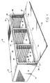
- the compact disk container storage device is illustrated in a perspective view in Fig. 1 and is designated by the general reference character 10 .
- the storage device 10 illustrated in Fig. 1 is the particular embodiment adapted to contain twenty four jewel boxes 11 in distinct slots.
- the jewel boxes 11 (shown in Fig. 2 and 3), when the storage device 10 is fully loaded, are arrayed in three columns, each of the columns having slots adapted to receive eight of the boxes 11 .
- a jewel box 11 is completely installed within the fifth slot from the top on the right column and is partially installed in the fifth slot from the top in the center column.
- the storage device 10 is constructed utilizing an exterior frame member 12 to enclose a rectangular solid shaped volume.
- the exterior frame member 12 includes a left side wall 14 , a rear wall 16 including a pair of inwardly protruding structural central ribs 17 , a right side wall 18 , a top wall 20 and a bottom wall 22 .
- the remaining side of the exterior frame member 12 is open to provide a front aperture 22 .
- the front aperture 22 is adaptable for being closed by a door 26 . When the door 26 is in a closed position, the entire internal volume of the exterior frame member 14 in enclosed in a substantially dust free manner.
- the door 26 is attached via a pair of hinges 27 to an interior frame member 28 is adapted for slidably fitting within the exterior frame member 12 .
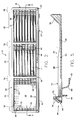
- the interior frame 28 includes a left side wall 30 , a right side wall 32 , a top wall 34 , and a bottom wall 36 .
- the interior frame 28 is not enclosed fore and aft, but includes a rear opening 38 and front opening 40 created by the rear and front edges of the walls 30 , 32 , 34 , and 36 respectively.
- the front opening 40 is framed by a front ridge 42 which extends outward so as to abut smoothly against the front edges of the walls 14 , 18 , 20 , and 22 of the exterior frame member 12 .
- the interior frame 28 is divided into three distinct storage column compartments, these being a left compartment 43 , a center compartment 44 and a right compartment 45 .
- the means of separation include a left divider wall 46 and a right divider wall 48 for each of the storage column compartments 43 , 44 and 45 .
- the left compartment 43 the function of the left divider wall 46 is performed by the left interior side wall 30 .
- the center and right compartments 44 and 45 the left divider wall 46 and the right divider wall 48 are separate components.
- Each of the compartments 43 , 44 and 45 is divided into a plurality, in the preferred embodiment, eight, of slots 50 for receiving the jewel boxes 11 .
- the vertical definition of slots 46 is determined by slot ledges 52 formed on the sides of the left divider walls 46 and the right divider walls 48 facing into the storage column compartments 43 , 44 and 45 .
- each of the interior facing walls is provided with seven slot ledges 52 , each having a respective opposing slot ledge 52 on the opposite wall of the same compartment.
- a left mechanism tube column 54 corresponds to left compartment 43
- a center mechanism tube column 56 corresponds to the center compartment 44
- a right mechanism tube column 58 corresponds to the right compartment 45 .
- Each of the mechanism tube columns 54 , 56 and 58 in the preferred embodiment 10 , includes eight rectangular tubes 59 bounded to the right by the left divider wall 48 for the corresponding compartment and to the right by left divider wall 46 (except in the case of the right mechanism tube column 58 in which case the right boundary is the right side exterior wall 18 .)
- the upper and lower boundaries of the rectangular tubes 59 are provided by the slot ledges 52 which extend throughout except for the uppermost and lowermost rectangular tubes 59 which are bounded respectively by the top interior wall 34 and the bottom interior wall 56 . Since each of the rectangular tubes 59 is a portion of the interior frame member 28 they are open both to the front and to the rear.
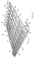
- each of the mechanism tube columns 54 , 56 and 58 will contain a release mechanism assembly 60 .
- the release mechanism 60 is shown in a perspective view in Fig. 4.
- the securing/release assembly 60 includes a torsion post 62 which extends vertically from top to bottom of the assembly 60 and a series of individual lever elements 64 .
- the securing/release mechanism assembly 60 adapted for insertion into the preferred embodiment of the storage device 10 there are eight lever elements 64 for each assembly 60 .
- the preferred embodiment of the mechanism assembly 60 is an integrally formed unitary element with the torsion post 62 providing the connecting component and the fulcrum/pivot about which the lever elements 64 rotate. In this manner, each of the lever elements 64 is physically connected to each of the other lever elements in such a manner that torque applied to one will be partially transmitted throughout the assembly 60 .
- the mechanism assembly 60 is installed in each of the mechanism tube columns 54 , 56 , and 58 by inserting the mechanism assembly 60 from the rear of each of the mechanism tube columns 54 , 56 or 58 .
- One lever element 64 will fit into each of the rectangular tubes 59 .
- a semicircular post detent 66 is formed in the slot ledge 52 at the center of the rear of each of the rectangular tubes 59 .
- the post detent 66 is adapted for receiving the torsion post 62 when the mechanism assembly 60 is installed to its proper position.
- the detent secures the fulcrum of the mechanism 60 such thatit is stationary with respect to the slot 50 .
- the interaction of the torsion post 62 with the post detent 66 prevents the mechanism assembly 60 from sliding forward within the mechanism tube columns more than is desired. Slippage to the rear is prevented by a variety of factors which will be discussed in more detail as follows.
- the lever elements 64 of the securing/release mechanism assembly 60 include a large number of integral components formed therein.
- the forwardmost portion of the element 64 is a release button 68 which may include a series of friction ridges 70 formed on the surface thereof make it more easily manipulable by the user's finger.
- the rear portion of the release button 68 provides a securing surface 72 for overlapping and abutting against the front edge of the jewel box 11 when the jewel box 11 is contained within the slot 50 (see column 45 in Fig. 3).
- the securing surface 72 also abuts against the front edge of the right divider wall 48 to prevent the mechanism assembly 60 from sliding rearward.
- the release button 68 is situated at the front end of a lever arm 74 .
- the rear end of the lever arm 74 terminates in a wedge member 76 which is adapted to abut against the rear right corner of the jewel box during the installed mode of the device 10 .
- the wedge 76 also applies ejection force to the jewel box 11 when desirable.
- the lever arm 74 is provided with a return spring arm 80 which extends outward therefrom in a curved manner.
- the return spring arm 80 is of the expansion type, resilient and has a shape such that it abuts against the interior of the left divider wall 46 (or in the case of the right mechanism tube column 58 , the right side exterior wall 18 ) and operates to urge the lever arm 74 and thus the entire lever element 64 to the left so as to have the securing surface 72 maximally overlap the front edge of the right divider wall 48 and the maximum portion of the front surface of the jewel box 11 .
- a small protrusion 82 is provided on the portion of the return spring arm 80 which abuts against the left divider wall 46 .
- the protrusion 82 provides a contact point with the left divider wall 46 and may be adjusted in size during the molding process in order to achieve desired degree of tension created by the spring arm 80 on the lever element 64 .
- the stop post 84 is a rigid element having a length such that when the return spring arm 80 has been compressed to the desired degree, the stock post 84 will contact the right divider wall and prevent additional compression.
- the lever arm 74 includes a vertical lever arm wall element 86 , and pair of a horizontal strengthening beams 88 , provided to increase the rigidity and durability of the lever arm 74 .
- a portion of each strengthening beam 88 is removed near the rear portion of the lever arm 74 to provide clearance angling 90 .
- the clearance angling 90 is a six degree slope towards the lever arm wall 86 in order to allow the strengthening beams 88 to avoid contact with the rear portion of the right divider wall 48 when the release button 68 is forced rightward and the return spring arm 80 is compressed.
- the preferred embodiment 10 includes only four separate molded elements. These are the exterior frame member 12 , the interior frame member 28 , the door 26 and the securing/release mechanism assembly 60 . Of course, in the embodiment 10 shown, three separate mechanism assemblies are combined within the single storage device 10 . The elements are adapted to frictionally fit and physically snap within each other such that no special connecting hardware is required, with the exception that it is desirable to use hinging hardware 27 to attach the door 26 .
- the overall shape of the device is a rectangular solid.
- the dimensions are dependent upon the precise contents involved, but for use with standard compact disk jewel boxes 11 , the embodiment 10 has an overall width of 46.83 cm, (18.66 in.), a height of 12.02 cm (4.79 in.) and a depth of 16.94 cm (6.75 in.).
- Each of the storage column compartments 43 , 44 and 45 has a width of 12.37 cm (4.93 in.) and a total height of 10.09 cm (4.02 in.).
- Each of the slots 50 has a height of 1.13 cm (0.45 in.) while the slot ledges 52 extend a distance of 0.63 cm (0.25 in.) into the storage compartments 43 , 44 and 45 while having a thickness of 0.15 cm (0.06 in.).
- the interior divider walls 46 and 48 extend a distance of 10.87 cm (4.33 in.) from front to back.
- the mechanism tube columns 54 , 56 and 58 have a width of 2.47 cm (0.985 in.) and are otherwise of the same dimensions as the storage column compartments 43 , 44 and 45 .
- the vertical dimensions of the securing/release mechanism assembly 60 are adapted to fit within the mechanism tube columns 54 , 56 and 58 with the portions of the torsion post 62 between adjacent lever elements 64 having a length of 0.20 cm (0.080 in.)
- the release button 68 has a total width of 2.38 cm (0.950 in.) and the slanted portion thereof including the friction ridges 70 , represents a width of 1.51 cm (0.600 in.).
- the lever arm 74 between the rear of the release button 68 and the front of the wedge 76 , has a length of 13.18 cm (5.25 in.).
- the wedge 76 is in the form of a right triangle having a base of 1.76 cm (0.700 in.) and a side (coextensive with the lever arm 74 of )2.48 cm (0.989 in.).
- the stop post 84 has a length of 0.879 cm (0.350 in.) and the return spring arm 80 extends outward a distance of 1.51 cm (0.600 in.) and rearward a distance of 1.88 cm (0.750 in.) from its point of attachment to the lever arm 74 .
- the vertical thickness of the lever arm wall 86 , and all other vertical components of the lever element 64 is 1.08 cm (0.430 in.).
- the number of objects to be stored within the device 10 is also entirely a matter of choice. It is envisioned that, in addition to the preferred embodiment 10 , alternate embodiments of the same device will be constructed, with one such emodiment including two, rather than three, storage column compartments and another having only a single storage column compartment. Furthermore, the number of slots within each storage column compartment may be modified as desired. It is presently envisioned that other embodiments utilizing only six slots per compartment will be constructed. None of these alternate embodiments significantly alter the nature or operation of the invention.
- the selection of materials for the construction of the device 10 is largly a matter of choice, the preferred material for the exterior frame member 12 and the interior frame member styrene. Other materials of the rigid plastic family are also quite adequate. Although cost considerations make them unlikely choices, metal or wood designing are feasible as well, rigidity and strength being the primary considerations.
- the frame members are selected to be opaque, although transparency or translucency will not in any way alter their effectiveness. Color is entirely a matter of individual choice.
- the door 26 is ordinarily selected to be a transparent or nearly transparent material which provides visual access to the contents of the device 10 when the door 26 is closed.
- the door 26 is contructed of ABS or styrene. Although glass or various other materials may be substituted without altering the nature of the invention. It may also be aesthetically desirable to utilize an opaque door.
- the securing/release mechanism assembly 60 is an integral molded plastic element in the preferred embodiment 10 .
- the integral construction is important to the effective operation since the torsion post 62 operates to cause all of the lever elements 64 to be torsionally dependent on each of the others. This prevents a individual lever element 64 from slipping or otherwise operating totally independently of the others within the same mechanism assembly 60 .
- One result of this interaction is that the mechanism assemblies 60 can only be disassembled by simultaneously releasing all of the release buttons 78 on the associated lever arms 74 at once in order to slide the assembly 60 rearward through the rectangular tubes 59 . Accidental disassembly is thus less effectively eliminated.
- the integral construction of the mechanism assembly 60 has been found to be the optimal way to achieving the desired results, there are other methods of constructing the assembly 60 to achieve the same goals.
- One such method is to torsionally connect the lever element 64 together in some other manner, such as by a rubber band placed about each of the lever arm 74 from top to bottom in the column.
- a common vertical post about which each of the lever elements pivot may also be provided.
- the preferred material for the mechanism assembly 60 is polypropylene or K-resin and the thicknesses of the torsion posts 62 are selected such that a rotation of six degrees is permitted with maximum material memory and resiliency and with minimal degredation of the torsion post material upon repeated use. For aesthetic purposes it may be desirable to cause the mechanism assembly 60 to have a different color appearance from that of the exterior frame 12 and the interior frame 28 .
- the present invention is adapted to be utilized for storage of solid objects, especially solid objects in the shape of rectangular solids and most specifically the preferred embodiment 10 is designed for use with the jewel boxes 11 in which audio compact disks are sold.
- the invention is adapted for storing a plurality of the jewel boxes 11 in a compact, readily accessable manner and in an aesthetically pleasing array. Reference is made to the figures of the drawing to aid in understanding the manner in which the storage device 10 operates to effectively store, secure and, when desired, release the jewel boxes 11 which are stored therein.
- the slot 50 in the left storage column compartment 43 is shown as empty, that of the right storage column compartment 45 has a jewel box 11 fully installed therein, and the slot in the center storage column compartment 44 illustrates a slot 50 having the jewel box 11 in the fully ejected position.
- the empty slot it is seen that the force of the return spring arm 80 causes the securing surface 72 to extend completely beyond the front edge of the right divider wall 48 until the strengthening beams 88 abut against the right divider wall 48 .
- the user will simply vertically and horizontally align the jewel box 11 so that it fits between the slot ledges 52 and push rearward.
- the angled front of the release button 68 would cause the release button 68 to be pushed rightward by the rearward force on the jewel box 11 until the distance between the left edge of the release button 68 and the opposing right divider wall 48 is sufficient to permit the jewel box 11 to pass there between.
- the jewel box 11 is then continually forced rearward until its front right corner passes the release button 68 and the rear right corner engages the wedge 76 .
- the user applies rightward pressure to the release button 68 . Slippage in applying this pressure is minimized by the presence of the friction ridges 70 .
- the rightward pressure on the release button acts to compress the return spring arm 80 , remove the abutment of the securing surface 72 from the front edge of the jewel box 11 so as to allow release and also to force the wedge 76 to apply positive pressure against the rear right corner of the jewel box 11 .
- the release button 68 is slid rightward the lever arm 74 flexes with increased torsion force since the abutment of the securing surface against the jewel box 11 prevents release. The wedge 76 cannot slide until the jewel box 11 is free to move.
- the release is a sudden event and the lever arm 74 and wedge 78 snap in such a manner as to rapidly urge the jewel box 11 forward out of the slot 50 .
- the degree of the releasing force provided to the jewel box 11 is limited by the stop post 84 and by sliding friction such that the jewel box 11 is typically only forced forward to the position shown in the center storage compartment 44 . This will be somewhat dependent upon the materials and thicknesses of the lever element 64 but represents the desired goal to which other factors are adjusted. In this position the jewel box 11 is still supported on the slot ledges 52 and will not fall out of the device. Instead, the jewel box 11 has a sufficient exposed surface that the user may grasp it and remove it manually the remaining distance.
- the force of the return spring arm 80 causes the lever element 64 to again rotate back to the position shown in the left storage column compartment 43 .
- the stop post 84 becomes broken, the interaction of the strengthening beam 88 in the area of the clearance angling 90 with the edge of the left divider wall 46 will provide an alternative limiting of the degree of rotation of the lever element 64 . Both forms of limiting the rotation are desirable for the dual purposes of causing the jewel box 11 to be ejected only to a desired distance and further to prevent undue strain upon the torsion post 62 .
- the storage device 10 of the present invention is extremely suitably adapted for use by owners of compact disk containers (jewel boxes) or any other rectangular solid object. It provides extremely secure and convenient access to the contents, contains a convenient number of objects and provides exterior visual access. Hence, it is expected that the invention will acheive extreme desirability in the marketplace.
Landscapes
- Packaging For Recording Disks (AREA)
- Packaging Of Annular Or Rod-Shaped Articles, Wearing Apparel, Cassettes, Or The Like (AREA)
Claims (6)
- Vorrichtung zum Aufbewahren einer Vielzahl einzelner Gegenstände, mit einem hohlen äußeren Rahmenelement (12), mit einem inneren Rahmenelement (28), das das Innere der Vorrichtung in eine Vielzahl von Schlitze (50) zur Aufnahme der Gegenstände unterteilt, wobei jeder der Schlitze von einer offenen Seite her zugänglich ist, und mit einer Arretier/Freigabe-Einrichtung (60), die jedem der Schlitze (50) zugeorndet ist und durch die jeweils einer der Gegenstände darin arretiert und bei entsprechender Betätigung freigegeben und derart ausgeworfen wird, daß der ausgeworfene Gegenstand von außerhalb der Einrichtung von Hand zugänglich ist, wobei das äußere Rahmenelement (12) eine offene Seite aufweist und die Arretier-/Freigabe-Einrichtung (60) folgendes besitzt: einen Hebelteil (64), der in einer Ebene um einen Drehpunkt/Drehachse (62) frei rotieren kann, wobei der Drehpunkt/Drehachse (62) gegenüber dem Fach fest ist und sich zwischen dem vorderen Teil und dem hinteren Teil des Hebels befindet, einen Arretierflächenbereich (72), der am der Vorderseite des Fachs entsprechenden Ende des Hebels vorgesehen ist, wobei die Arretierfläche einen Bereich der Frontfläche des Gegenstandes überdeckt, wenn dieser in das Fach eingelegt ist, eine Antriebseinrichtung (80), die den Arretierflächenbereich beständig in eine Stellung drängt, in der er den Gegenstand maximal überdeckt, und eine Freigabeeinrichtung (68,70), die für den Benutzer zugänglich und derart ausgebildet ist, daß Druck auf die Auslöseeinrichtung die Antriebskraft überwindet und bewirkt, daß der Hebelteil (64) um den Drehpunkt/Drehachse (62) in eine Stellung gedreht wird, in der die Arretierfläche die Frontfläche des Gegenstandes nicht mehr überdeckt; dadurch gekennzeichnet, daß ein dreieckiges keilförmiges Teil (78) am der hinteren Seite des Fachs entsprechenden Ende des Hebelteils angebracht und derart ausgebildet ist, daß er dann, wenn der Gegenstand in das Fach eingelegt ist, an einer hinteren Kante des Gegenstandes derart anliegt, daß ein Druck auf die Freigabeeinrichtung den keilförmigen Teil gegen die hintere Kante des Gegenstandes druckt und dadurch den Gegenstand aus dem Fach teilweise auswirft.
- Vorrichtung nach Anspruch 1, dadurch gekennzeichnet, daß die Schlitze in zwei oder mehr vertikalen Spalten angeordnet sind und daß die Arretier/Freigabe-Einrichtung (60) für jeden der Schlitze (50) in jeder Spalte mit jeder der anderen Arretier/Freigabe-Einrichtungen in der Spalte integriert verbunden ist.
- Vorrichtung nach Anspruch 1 oder 2, dadurch gekennzeichnet, daß die Antriebseinrichtung einen Federarm (80) aufweist, der am Hebelteil angebracht ist, und daß der Federarm (80) eine Expansionsfeder ist und sich an einem Stützelement (84) abstützt, wobei das Stützelement gegenüber dem Fach stationär ist.
- Vorrichtung nach einem der vorhergehenden Ansprüche, dadurch gekennzeichnet, daß die Freigabeeinrichtung einen Knopf (68) aufweist, der angrenzend an den Arretierflächenbereich angebracht ist, und daß der Knopf Reibungserhebungen (70) aufweist, damit, ohne abzurutschen, Druck auf den Knopf ausgeübt werden kann.
- Vorrichtung nach einem der vorhergehenden Ansprüche, dadurch gekennzeichnet, daß die Kraft, die einen der Gegenstände in ein leeres Fach schiebt, die Freigabeeinrichtung ohne deren weitere Berührung durch den Benutzer betätigt.
- Vorrichtung nach einem der vorhergehenden Ansprüche, dadurch gekennzeichnet, daß in ihr Compact Disk-Hüllen aufbewahrbar sind, wobei jeweils eine Hülle in jedem der Schlitze aufgenommen ist.
Priority Applications (1)
| Application Number | Priority Date | Filing Date | Title |
|---|---|---|---|
| AT86906680T ATE98455T1 (de) | 1985-11-04 | 1986-10-22 | Kompaktplattenbehaelteranordnung. |
Applications Claiming Priority (2)
| Application Number | Priority Date | Filing Date | Title |
|---|---|---|---|
| US79507285A | 1985-11-04 | 1985-11-04 | |
| US795072 | 1985-11-04 |
Publications (3)
| Publication Number | Publication Date |
|---|---|
| EP0245367A1 EP0245367A1 (de) | 1987-11-19 |
| EP0245367A4 EP0245367A4 (de) | 1988-09-28 |
| EP0245367B1 true EP0245367B1 (de) | 1993-12-15 |
Family
ID=25164588
Family Applications (1)
| Application Number | Title | Priority Date | Filing Date |
|---|---|---|---|
| EP19860906680 Expired - Lifetime EP0245367B1 (de) | 1985-11-04 | 1986-10-22 | Kompaktplattenbehälteranordnung |
Country Status (6)
| Country | Link |
|---|---|
| EP (1) | EP0245367B1 (de) |
| JP (1) | JPS63501211A (de) |
| AU (1) | AU583099B2 (de) |
| CA (1) | CA1275146A (de) |
| DE (1) | DE3689419T2 (de) |
| WO (1) | WO1987002558A1 (de) |
Families Citing this family (4)
| Publication number | Priority date | Publication date | Assignee | Title |
|---|---|---|---|---|
| US4867311A (en) * | 1988-11-21 | 1989-09-19 | Metcalf Darrell J | Computer diskette dispenser and storage device |
| DE3942845A1 (de) * | 1989-12-23 | 1991-06-27 | Fischer Artur Werke Gmbh | Aufnahmebehaelter fuer magnetbandkassetten |
| DE19606491C1 (de) * | 1996-02-22 | 1997-05-28 | Werner Moritz | Bevorratungsbox für CD's, Kassetten oder dergl. |
| GB2322794B (en) * | 1997-03-07 | 2000-03-15 | Eml Ltd | Improvements in or relating to storage units |
Family Cites Families (11)
| Publication number | Priority date | Publication date | Assignee | Title |
|---|---|---|---|---|
| US3969007A (en) * | 1975-02-21 | 1976-07-13 | Data Packaging Corporation | Cassette dispenser |
| AU494906B2 (en) * | 1975-10-21 | 1977-04-28 | Ido Inventions And Development Of Novelties Ag | Container for magnetic tape cassette |
| US4121877A (en) * | 1977-03-21 | 1978-10-24 | Brown James L | Magnetic tape cassette storage case |
| US4087138A (en) * | 1977-04-06 | 1978-05-02 | Mcrae William P | Dispensing cabinet |
| US4162112A (en) * | 1978-01-23 | 1979-07-24 | Minnesota Mining And Manufacturing Company | Storage assembly for a tape magazine |
| GB2021072A (en) * | 1978-03-17 | 1979-11-28 | St John Rumble Clive | A storage device for tape cassettes and/or cartridges |
| US4265369A (en) * | 1979-02-09 | 1981-05-05 | Aboussouan Michel F | Tape cartridge dispenser |
| US4270817A (en) * | 1979-02-23 | 1981-06-02 | Mcrae William P | Cassette storage and dispensing device |
| US4330162A (en) * | 1980-03-04 | 1982-05-18 | Aboussouan Michel F | Tape cartridge storage device |
| DE3246041A1 (de) * | 1982-12-13 | 1984-06-14 | IDN Inventions and Development of Novelties AG, 7002 Chur | Behaelter zur aufbewahrung von magnetbandkassetten |
| FR2552915B1 (fr) * | 1983-09-29 | 1988-09-16 | Fouassier Jean Pierre | Dispositif de rangement modulable pour disques compacts, cassettes d'enregistrement magnetique et analogues |
-
1986
- 1986-03-17 AU AU54772/86A patent/AU583099B2/en not_active Ceased
- 1986-03-25 CA CA000504989A patent/CA1275146A/en not_active Expired
- 1986-10-22 WO PCT/US1986/002273 patent/WO1987002558A1/en not_active Ceased
- 1986-10-22 DE DE86906680T patent/DE3689419T2/de not_active Expired - Fee Related
- 1986-10-22 EP EP19860906680 patent/EP0245367B1/de not_active Expired - Lifetime
- 1986-10-22 JP JP61505706A patent/JPS63501211A/ja active Pending
Also Published As
| Publication number | Publication date |
|---|---|
| AU583099B2 (en) | 1989-04-20 |
| DE3689419D1 (de) | 1994-01-27 |
| DE3689419T2 (de) | 1994-04-07 |
| WO1987002558A1 (en) | 1987-05-07 |
| EP0245367A4 (de) | 1988-09-28 |
| JPS63501211A (ja) | 1988-05-12 |
| EP0245367A1 (de) | 1987-11-19 |
| CA1275146A (en) | 1990-10-09 |
| AU5477286A (en) | 1987-05-07 |
Similar Documents
| Publication | Publication Date | Title |
|---|---|---|
| EP0658148B1 (de) | Brieftaschenartige compact disc lagereinheit | |
| US4850477A (en) | Combination display package and flip file holder for compact discs | |
| CA1309064C (en) | Theft resistant retail container | |
| US5334904A (en) | Compact disc case | |
| US4819802A (en) | Holder and ejector assembly for cassette-type casings | |
| US5191983A (en) | Modular storage rack | |
| US5366073A (en) | Storage container for media records | |
| US5285893A (en) | Storage case for multiple compact discs and related printed material | |
| US5285897A (en) | Tape cassette case | |
| US5363956A (en) | Container for plurality of stackable objects | |
| US4900107A (en) | Compact disk container storage device | |
| US7191899B2 (en) | Disc cartridge storage case having presentation stand | |
| US4330162A (en) | Tape cartridge storage device | |
| US6332656B1 (en) | Dispensing and storage unit for discs and the like | |
| EP0245367B1 (de) | Kompaktplattenbehälteranordnung | |
| AU664881B2 (en) | Storage container for mini-disk cartridges | |
| JPH04279484A (ja) | 角形カセット用ホルダ | |
| CA2457417A1 (en) | Insertable tray for a multiple disc storage container | |
| KR100436285B1 (ko) | 컴팩트 디스크 케이스 | |
| US5104207A (en) | Means providing easy extraction of video cassettes and the like from storage jackets therefor | |
| EP0491769B1 (de) | Gehäuse zur speicherung eines aufnahmeträgers, wie einer magnetbandkassette, laserplatte oder vergleichbarem | |
| EP0559273A2 (de) | Verpackung für eine scheibenförmige Platte mit einer zentralen Oeffnung | |
| KR20010098645A (ko) | 디스크 수납체 수납 케이스 | |
| AU707542B2 (en) | A wallet style compact disc storage unit | |
| EP0584355A1 (de) | Speicher für informationsaufzeichnungsträger |
Legal Events
| Date | Code | Title | Description |
|---|---|---|---|
| PUAI | Public reference made under article 153(3) epc to a published international application that has entered the european phase |
Free format text: ORIGINAL CODE: 0009012 |
|
| AK | Designated contracting states |
Kind code of ref document: A1 Designated state(s): AT BE CH DE FR GB IT LI LU NL SE |
|
| 17P | Request for examination filed |
Effective date: 19870929 |
|
| A4 | Supplementary search report drawn up and despatched |
Effective date: 19880928 |
|
| 17Q | First examination report despatched |
Effective date: 19900426 |
|
| GRAA | (expected) grant |
Free format text: ORIGINAL CODE: 0009210 |
|
| AK | Designated contracting states |
Kind code of ref document: B1 Designated state(s): AT BE CH DE FR GB IT LI LU NL SE |
|
| PG25 | Lapsed in a contracting state [announced via postgrant information from national office to epo] |
Ref country code: IT Free format text: LAPSE BECAUSE OF FAILURE TO SUBMIT A TRANSLATION OF THE DESCRIPTION OR TO PAY THE FEE WITHIN THE PRE;WARNING: LAPSES OF ITALIAN PATENTS WITH EFFECTIVE DATE BEFORE 2007 MAY HAVE OCCURRED AT ANY TIME BEFORE 2007. THE CORRECT EFFECTIVE DATE MAY BE DIFFERENT FROM THE ONE RECORDED.SCRIBED TIME-LIMIT Effective date: 19931215 Ref country code: CH Effective date: 19931215 Ref country code: BE Effective date: 19931215 Ref country code: NL Effective date: 19931215 Ref country code: AT Effective date: 19931215 Ref country code: LI Effective date: 19931215 Ref country code: SE Effective date: 19931215 |
|
| REF | Corresponds to: |
Ref document number: 98455 Country of ref document: AT Date of ref document: 19940115 Kind code of ref document: T |
|
| REF | Corresponds to: |
Ref document number: 3689419 Country of ref document: DE Date of ref document: 19940127 |
|
| ET | Fr: translation filed | ||
| REG | Reference to a national code |
Ref country code: CH Ref legal event code: PL |
|
| NLV1 | Nl: lapsed or annulled due to failure to fulfill the requirements of art. 29p and 29m of the patents act | ||
| PGFP | Annual fee paid to national office [announced via postgrant information from national office to epo] |
Ref country code: GB Payment date: 19940915 Year of fee payment: 9 |
|
| PLBE | No opposition filed within time limit |
Free format text: ORIGINAL CODE: 0009261 |
|
| STAA | Information on the status of an ep patent application or granted ep patent |
Free format text: STATUS: NO OPPOSITION FILED WITHIN TIME LIMIT |
|
| PGFP | Annual fee paid to national office [announced via postgrant information from national office to epo] |
Ref country code: FR Payment date: 19941024 Year of fee payment: 9 |
|
| PG25 | Lapsed in a contracting state [announced via postgrant information from national office to epo] |
Ref country code: LU Free format text: LAPSE BECAUSE OF NON-PAYMENT OF DUE FEES Effective date: 19941031 |
|
| 26N | No opposition filed | ||
| PGFP | Annual fee paid to national office [announced via postgrant information from national office to epo] |
Ref country code: DE Payment date: 19941221 Year of fee payment: 9 |
|
| PG25 | Lapsed in a contracting state [announced via postgrant information from national office to epo] |
Ref country code: GB Effective date: 19951022 |
|
| GBPC | Gb: european patent ceased through non-payment of renewal fee |
Effective date: 19951022 |
|
| PG25 | Lapsed in a contracting state [announced via postgrant information from national office to epo] |
Ref country code: FR Effective date: 19960628 |
|
| PG25 | Lapsed in a contracting state [announced via postgrant information from national office to epo] |
Ref country code: DE Effective date: 19960702 |
|
| REG | Reference to a national code |
Ref country code: FR Ref legal event code: ST |