EP0244946A2 - Construction d'un réservoir sous pression pour milieu corrosif - Google Patents
Construction d'un réservoir sous pression pour milieu corrosif Download PDFInfo
- Publication number
- EP0244946A2 EP0244946A2 EP87302867A EP87302867A EP0244946A2 EP 0244946 A2 EP0244946 A2 EP 0244946A2 EP 87302867 A EP87302867 A EP 87302867A EP 87302867 A EP87302867 A EP 87302867A EP 0244946 A2 EP0244946 A2 EP 0244946A2
- Authority
- EP
- European Patent Office
- Prior art keywords
- tank
- side wall
- coating
- interior
- annular body
- Prior art date
- Legal status (The legal status is an assumption and is not a legal conclusion. Google has not performed a legal analysis and makes no representation as to the accuracy of the status listed.)
- Withdrawn
Links
Images

Classifications
-
- F—MECHANICAL ENGINEERING; LIGHTING; HEATING; WEAPONS; BLASTING
- F24—HEATING; RANGES; VENTILATING
- F24H—FLUID HEATERS, e.g. WATER OR AIR HEATERS, HAVING HEAT-GENERATING MEANS, e.g. HEAT PUMPS, IN GENERAL
- F24H1/00—Water heaters, e.g. boilers, continuous-flow heaters or water-storage heaters
- F24H1/18—Water-storage heaters
- F24H1/181—Construction of the tank
Definitions
- This invention relates to improvements in hot water steel tanks having corrosion inhibiting coatings on interior surfaces.
- a ceramic or glass lined hot water tank typically includes a cylindrical side wall with a cylindrical top having a concave interior surface to define a "plus” head for the tank.
- the bottom of the tank has a convex interior surface to define a "minus" bottom for the tank.
- This arrangement has been manufactured for a considerable number of years where the technique is normally to weld the top to the cylindrical side wall rolled from a flat rectangular blank and to coat the interior of the bottom open ended tank. A precoated bottom having the convex interior surface is then welded to the base of the tank.
- the hot water at the top of the tank increases any corrosive reaction because released gases, which includes oxygen, are free to chemically react with and corrode any bare metal exposed by poor glazing or coatings. It is also appreciated that the speed of chemical reaction doubles with every l0°C increase in temperature.
- the abutting nature of the fit of the tank top with the tank side is not necessarily perfect because of nicks or other imperfections in the outer periphery of the cylindrical portion of the tank side wall and the top. Hence it is quite possible, even with the greatest of care in applying the glazing material that some uncoated areas exist at the joint between the tank top and the tank side wall.
- U.S. Patent 3,l99,7ll discloses a fire extinguishing tank which may contain pressurized materials.
- the tank is constructed of materials which are not corroded by the contents hence no protective or corrosion inhibiting coating is applied to the tank interior.
- the tank may be formed of copper or the like where the components are soldered together.
- a similar system is provided in U.S. Patent 3,952,904 wherein again the material of construction is not corroded by its contents.
- the plastic bottom of concave interior shape is sonic w elded to the plastic side walls of the barrier where a seal is provided at the connection to prevent leakage.
- No protective coating is required in the system nor is any welding used in making the connection where the heat of the weld could in any way affect an interior protective coating.
- a tank for containing a corrosive medium has a corrosion inhibiting coating on interior surfaces thereof.
- the tank comprises a cylindrical steel side wall and first and second ends for securement to and closure of the tank. At least the first end is concave-shaped and projects outwardly of the tank interior. At least the first end is secured to the tank by a connecting means having an annular body portion for controlling effect of welding heat on the corrosion inhibiting coating as previously applied to the tank side wall interior surface and the first end interior surface.
- a first portion of the annular body portion is connected at a first connection peripherally of the first end.
- a second portion of the annular body portion is connected at a second connection to a cylindrical end portion of the side wall.
- One of the first and second portions and corresponding first or second connection is coated with the corrosion inhibiting coating.
- the other of the first and second portions is a welded connection.
- the annular body portion controls temperature to which the coating is heated by spacing the welded connection a predetermined extent from the corrosion inhibiting coating.
- a process for connecting a steel end to a corresponding end portion of a steel tank for containing a corrosive medium.
- the tank has a cylindrical side wall with an interior surface, the end being circular and having a concave shape extending outwardly of tank interior and connecting means for connecting the end to the tank side wall end portions.
- the process comprises connecting the connecting means to either of the end or the tank side wall.
- the interior surface of the tank, interior concave surface of the end and an exposed portion of the connecting means are coated with a corrosion inhibiting coating.
- the connecting means is welded to the end or the tank side wall.
- the coated exposed portion of the connecting means abuts the coating on the end interior surface of the tank side wall interior surface to form a coating juncture.
- Temperature to which the coating juncture is heated is controlled by predetermining an extent to which the connecting means spaces the welding of the connecting means from the coating juncture.
- This invention is applicable to many forms of tank construction which contain mediums corrosive to the tank material; for example, steel tanks for containing water, gas cylinders for acidic gases, fire extinguishers and beer kegs.
- the preferred embodiments of this invention will be demonstrated in a hot water steel tank construction. However, it is appreciated that such embodiments are equally applicable in other tank constructions.
- Hot water tanks are used in residential and commercial establishments to heat and store water, normally at temperatures in the range of l20°F to l60°F, where the source of heat is normally by electrical heating elements or gas fired heating devices.
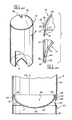
- a typical tank used in electrical type of water heater is shown in Figures l and 2.
- the tank l0 consists of a cylindrical side wall l2 with a first or bottom end l4 and a second or top end l6. The ends of the tank are welded to the cylindrical side wall to seal the tank and provide a compartment in which water is heated and stored as hot water. It is understood that the water inlet and apertures for electrical heating elements, as provided in the side wall l2, are not shown. Usually the hot water is taken from the top of the hot water heater via the outlet l8.
- the assembly of the hot water heater of the prior art device is normally accomplished by welding the end l6 to the side wall l2.
- the top end l6 has a peripheral end portion 20 which is fitted within the side wall upper end portion 22.
- the top end l6 is welded to the side wall end portion 22 by a fillet weld 24 which connects the upper edge 26 to the outer side wall 28 of the end l6.
- a bottom open-ended tank is therefore provided where the tank interior with the end l6 in place is coated with a corrosion inhibiting coating.
- the tank interior is coated with a glazing slurry which is commonly used in the art and consists of finely ground essentially ceramic powder suspended in water.
- the coating is applied to all internal surfaces including the interior concave surface 30 of the end l6 and also about the joint area 32 interior of the tank along with the tank side wall interior surface 34.
- the coating is wiped off the bottom edge 36 as well as a marginal interior portion of the tank side wall.
- the coated tank is then passed through a drier to remove water from the glazing slurry, and placed into a glazing furnace which operates normally at a temperature of about l600°F. This results in a smooth corrosion resistant coating on the tank interior.
- the bottom end l4 which has a convex interior surface is cleaned and glazed in a similar manner to the tank shell assembly.
- the glazing coating is wiped off in area 38 so as to be adjacent the cleaned end portion 36 of the side wall.
- the bottom l4 is inserted within the tank.
- the coating on the interior surface 40 of the tank bottom abuts the coating on the interior surface 34 of the side wall.
- a weld 42 is applied between surfaces 36 and 38.
- the weld 42 is sufficiently remote from the area generally designated 44, which is the juncture of the coatings on interior surfaces 34 and 40, that the heat from the welding process does not degrade the coatings. Normally such welding is carried out by a type of submerged-arc process.
- the provision of "plus" end at the bottom of the tank is a desired embodiment of the invention.
- the welding would be on the tank bottom portion in a area which is coated.
- the heat from the weld would travel directly through the tank bottom wall portion thereby degrading the ceramic coating.
- non-ceramic coatings such as polymeric coatings which include various suitable polyamides; for example Nylon II (trademark). Such degradation of the coating can result in its destruction and loss of corrosion inhibiting properties.
- a connection is provided for either end of the tank cylindrical side wall which can constitute either the top or bottom of the tank when in use.
- the cylindrical tank side wall l2 has fitted to its bottom end portion 36 a "plus" bottom end 46.
- the end 46 has a concave interior surface 48 which extends outwardly of the interior of the tank.
- the concave interior surface 48 has a semi-ellipsoidal shape.
- the end may be torispherical in shape as defined in ASME Boiler and Pressure Vessel Code, Section VIII, Division l, l977 Edition. Due to essentially constant material thickness the exterior surface 52 of the end 46 approximates the same shape.
- a connecting device generally designated 54 having an annular boby portion is used.
- the connecting device 54 is secured to the peripheral edge portion 56 of the exterior of the end 46. Such connection may be by welding or other suitable securing means.
- the interior surface 34 of the tank Prior to assembly of the end 46 to the cylindrical side wall l2 of the tank, the interior surface 34 of the tank is coated as well as the interior surface 48 and the exterior portion of the connecting means 54. Any excess applied coating in region 57, which is to be subsequently welded to the tank wall is wiped off. The tank interior end is also wiped off to leave opposing uncoated surfaces for welding.
- the end portion 46 is then inserted into the end 36 of the cylindrical side wall where the coatings on the connecting means 54 and on the interior surface 34 of the tank overlap and contact one another to seal the tank end.
- the connecting means is then welded to the end 36 by a fillet weld 58.
- the connecting device 54 is arranged to control the temperature to which the juncture of the overlapped coatings is heated by the process of welding the connecting means to the end 36. Such control on temperature is exercised by predetermining the extent to which the connecting device 54 spaces the fillet weld 58 from the juncture of the overlapped coati ng and also from the coating on the interior surface of the end and tank side wall.
- the connecting device 54 conducts heat from the welding region of weld 58 towards the juncture of the coatings. By trial and error, the extent to which the connecting device spaces the weld from the juncture of the coatings can provide a control on the temperature to which the coatings are heated.
- the temperature may be desired to control the temperature to an extent which minimizes or avoids any effect of welding heat on the coatings at the juncture.
- the stand 60 has a inwardly stepped portion 62 which is secured to the interior surface 64 of the connecting device.
- the stand has a peripheral bottom edge 66 which extends below the lowermost portion 68 of the end 46 to act as the support feet for the hot water tank when it is stood upright for use.
- the coating for the connecting device 54 for the end 46 and also for the interior 34 of the tank side wall l2 is shown in more detail in Figure 4.
- the connecting device 54 comprises an annular skirt portion having exterior surface 76 which is welded at 74 to the exterior surface 56 of the end portion.
- the skirt extends outwardly of the end portion and is stepped in area 84 to facilitate insertion of the end 46 into the tank.
- the coating 70 as applied to the interior surface 34 may be of a fired ceramic composition or of some polymeric composition, such as "Nylon".
- a slurry including ceramic particles is coated onto the interior surface 34 of the tank side wall.
- the lower circumferential end portion of the shell interior 72 does not include coating material hence this area is left uncoated after the tank side wall has been dried and fired.
- the end 46 and the connecting device 54 also have the slurried ceramic coating applied thereto over the entire interior surface 48 of the end, and overlapping the welded area 74 which includes the connection of the connecting device 54 to the external edge portion 56 of the end.
- the exterior surface 76 of the connecting device is also coated with the slurried material to provide thereby an essentially continuous coating 78.
- the lower portion 80 is left uncoated to provide an uncoated peripheral area 80 about the perimeter of the connecting device 54.
- the coatings which have been applied to the tank side wall interior surface and to the end 46, are then glazed, cured or fused.
- the end is then inserted into the tank end until the coated surfaces 70 and 78 contact in the region designated 82 on the connecting device exterior surface 76 and also on the lower portion of the coating 70 of the tank side wall.
- Such contacting of the coatings forms a seal about the periphery of the tank bottom end to prevent water leakage and thereby form effectively a continuous coating from the side wall onto the end 46.
- a significant circumferential band of contact area is provided for the contacting coatings.
- Such band area of contact ensures a seal about the peripheral juncture of coatings, because of the band height over which contact between the coatings can be established. If there is difficulty in providing a seal about the peripheral junctu re of the coatings, as discussed, it is possible by way of the connecting device to control the temperature to which the juncture of coatings is heated to fuse coatings in that area without totally degrading the coatings and losing any potential for a seal at this juncture. This is particularly applicable when the coatings are of a polymeric material, such as "Nylon" which can be fused when heated to the proper temperatures. It is appreciated that a sealant, such as an epoxy coating or gasket, may be applied to the juncture before welding. The heat of welding is then controlled by the connecting device to ensure that the epoxy sealant or gasket is not degraded.
- a sealant such as an epoxy coating or gasket
- the end portion is now in a position to be secured to the tank side wall l2.
- the connecting device 54 extends a sufficient distance outwardly of the juncture 82 of the coatings such that when the uncoated portion 80 is welded to the uncoated portion 72 of the tank side wall, the heat of the welding does not in any way degrade the non-corrosive characteristic of the coatings at least in the area of juncture 82 and inwardly thereof.
- Such connecting device 54 serves to space the welded area away from the coating not only on the connecting device 54 but also on the interior surface of the end 46 such that when the weld is completed a continuous coating remains on the bottom surface and side wall area of the tank.
- the welding which may be used to connect the connecting device 54 to the outer peripheral edge portion 56 of the end is done before the coating is applied to the end and connecting device hence the heat of the weld of that connection has no effect on the subsequent coating process.
- the coating overlaps the seamed area and any weld which may be present to coat and protect that area from corrosion by the contained liquid which is normally water.
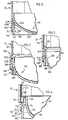
- the end 46 has a concave interior surface 86 which may be of the ellipsoidal, torispherical or hemispherical configuration as shown in Figure 3.
- the connecting device 54 includes the annular skirt portion 88 which extends outwardly of the interior of the tank. According to this embodiment the skirt portion 88 is a continuation of the wall portion 90 of the end as provided for by a reverse bend 92.
- the end 46 as fabricated from an essentially constant material thickness of steel is coated prior to insertion within the tank side wall l2 which has a coating on its interior surface 34. The coatings are such to form a juncture in the region 94 which effectively forms a seal about the bottom of the tank.
- Uncoated portions of the tank side wall in region 72 and 96 of the skirt exterior are provided so that a fillet weld 98 may be used to connect the end 46 to the tank side wall l2.
- the skirt of the connecting device 54 extends outwardly of the tank interior a sufficient distance so as to locate the fillet weld 98 at a region where the heat of the weld does not degrade the non-corrosive properties of the coating at least in the area of juncture 94 about the perimeter of the connecting device 54.
- FIG. 6 another embodiment is shown for the end 46 of the hot water tank for installation and connection to the tank side wall l2.
- the end 46 has a concave interior surface l00.
- the connecting device 54 comprises a skirt portion l02 having its upper end which is angled towards the bottom portion l04 of the end 46.
- a fillet weld at l06 connects the angle portion l08 of the skirt to the end 46.
- the assembly of the connector device 54 and the end 46 are coated in the manner similarly used in coating the other embodiments.
- the interior surface 34 of the side wall is coated, such that when the end 46 is inserted within the tank side wall the coatings contact and form a seal in the juncture region ll0.
- the uncoated portions of the tank end 72 and the connector skirt portion ll2 are connected by fillet weld ll4, the heat of which does not affect the coatings in the region ll0.
- Figure 7 is an alternative to that of Figure 6, where an arrangement is provided which permits the use of an end 46 which is the same as the other end used in connecting to the top portion of the tank side wall in accordance with the technique shown in Figure 2.
- the side wall l2 is stepped in region ll6.
- the connecting device 54 is a skirt portion ll8 which is welded at l20 to the peripheral edge portion l22 of the end 46.
- the end 46 with the connecting device 54 is coated independently of the side wall interior surface 34. In coating the end portion 46 the coating covers the seam area which includes the weld l20. After the end 46 is inserted in the tank end portion, the end is secured by way of a weld l24.
- the skirt ll8 extends sufficiently outwardly of the tank so as to locate the weld l24 a sufficient distance from the region l26 about which the coatings on the interior surface 34 of the tank and on the connecting device ll8 contact one another.
- the heat of weld from welding l24 does not degrade coatings in this area or interior thereof including the coating on the interior l28 of the end 46.
- FIG. 8 Another arrangement is provided in Figure 8 for connecting the end portion 46 to the tank side wall.
- the connecting device 54 includes a skirt portion l30 which is welded at seam l32 to the peripheral edge l34 of the end 46. The welded assembly is then curved inwardly to the extent shown in Figure 8 to provide for a lead in portion in inserting the end 46 within the tank side wall l2.
- the tank side wall l2 is provided with the coating 70 in the manner discussed with respect to Figure 4, the tank end 46 with connecting device 54 is coated with a coating l36 which extends over the seam area l32 and downwardly of the outer wall portion l38 of the skirt l30.
- a fairly close tolerance fit is provided between the uncoated portion of the outer surface l38 of the skirt l30 and the corresponding uncoated portion 72 of the tank side wall.
- the weld l40 is located a sufficient distance from the juncture l4l of the coating so as to not degrade same.
- the skirt l30 spaces the weld l40 from the coating l36 on the interior of the end 46.
- connection of the tank side wall to a "plus" end, bottom or top which has an internal diameter at its circumferential portion greater than the external diameter of the tank shell.
- This type of connection is shown in Figure 9, wherein the tank side wall l2 has the connecting device 54 secured at a first portion l42 to the exterior l44 of the tank side wall.
- the inner surface 34 of the tank is coated with the corrosion inhibiting coating including the connection area l46 and remaining exposed external surface l48 of the connecting device 54.
- the "plus" end which may be the bottom 46, has a coating on its interior surface 48 which overlaps the coating on surface l48 of the connecting device in the region l50.
- the second portion l52 of the connecting device is fillet welded at l54 to the end 46 to complete the assembly of the end to the tank side wall.
- the connecting device 54 spaces the fillet weld l54 a suffici ent distance from the overlapped region l50 to control the temperature to which the overlapped region of coatings is heated during the welding operation.
- FIG. l0 An alternative stand assembly for the hot water tank is provided in Figure l0.
- the end 46 is assembled to the tank side wall l2 in accordance with the structure generally shown in Figure 8.
- a foaming material such as urethane foam
- a prefabricated foamed base l56 is provided which receives the shape of the end 46.
- a shell assembly l58 may be assembled around the base and the tank leaving a cavity l60 between the tank exterior l58 and the tank side wall l2 and also about the top portion (not shown).
- a foam material is introduced into the cavity l60 to fill the cavity with an insulating foam material and solidify the structure once the foam urethane composition has set.
- This provides for a quick assembly technique for the hot water tank construction where the shell l58 including a platform l62 is now complete and ready for use where the platform includes projecting feet portions l64.
- the material thickness of the tank end compared to the thickness of the tank side wall for resisting stresses created by pressures within the tank are well understood in pressure tank design. This permits the use of thinner materials in the tank ends to considerably reduce the amount of material used in manufacturing the tanks knowing that the tank end can be designed to accommodate a predetermined stress.
- the material thicknesses for the tank top is usually l.6 times the tank side thickness and for the bottom "minus" head the thickness usually averages more than l.9 times th e tank side wall thickness.
- both ends may be of a thickness less than the tank side wall thickness. This results in significant material savings, to upwards of 28%, and considerably reduces failures of the tank in the region of the joint of tank top to side wall.
- the design provides for a significant glazing energy saving which can be realized in the range of l0 to 30% depending upon the shape for the tank ends.
- Another form of energy saving can be realized due to the overall reduction in tank surface area for the volume of water contained. Due to the reduced tank surface area, there is less heat loss so that less energy is required to maintain the water at the desired temperature.
- the method is conducted in the manner described where the significant advantage with one of the embodiments of the invention is that the tank side wall may be coated independently of the end portions.
- the interior of the side wall can be inspected for flaws before the ends are connected to the tank side wall.
- the threads of the outlet l8 can be independently inspected. This is particularly important when coatings of ceramic slurry are applied to the tank interior.
- the effectiveness of the coating can be inspected particularly about the seaming area of the connecting device.
Landscapes
- Engineering & Computer Science (AREA)
- Physics & Mathematics (AREA)
- Thermal Sciences (AREA)
- Chemical & Material Sciences (AREA)
- Combustion & Propulsion (AREA)
- Mechanical Engineering (AREA)
- General Engineering & Computer Science (AREA)
- Filling Or Discharging Of Gas Storage Vessels (AREA)
- Heat-Pump Type And Storage Water Heaters (AREA)
Applications Claiming Priority (2)
| Application Number | Priority Date | Filing Date | Title |
|---|---|---|---|
| CA000508818A CA1261770A (fr) | 1986-05-09 | 1986-05-09 | Cuve sous pression pour agent corrosif |
| CA508818 | 1986-05-09 |
Publications (2)
| Publication Number | Publication Date |
|---|---|
| EP0244946A2 true EP0244946A2 (fr) | 1987-11-11 |
| EP0244946A3 EP0244946A3 (fr) | 1988-04-20 |
Family
ID=4133112
Family Applications (1)
| Application Number | Title | Priority Date | Filing Date |
|---|---|---|---|
| EP87302867A Withdrawn EP0244946A3 (fr) | 1986-05-09 | 1987-04-02 | Construction d'un réservoir sous pression pour milieu corrosif |
Country Status (5)
| Country | Link |
|---|---|
| EP (1) | EP0244946A3 (fr) |
| JP (1) | JPS6322389A (fr) |
| CN (1) | CN87103389A (fr) |
| AU (1) | AU7098287A (fr) |
| CA (1) | CA1261770A (fr) |
Cited By (2)
| Publication number | Priority date | Publication date | Assignee | Title |
|---|---|---|---|---|
| GB2284657A (en) * | 1993-11-20 | 1995-06-14 | Imi Range Ltd | Storage vessels |
| CN102133958A (zh) * | 2011-01-17 | 2011-07-27 | 江阴东大新材料研究院 | 在钢质封闭容器内表面制备完整防腐涂层方法 |
Families Citing this family (2)
| Publication number | Priority date | Publication date | Assignee | Title |
|---|---|---|---|---|
| CN108622560A (zh) * | 2017-03-20 | 2018-10-09 | 中集集团集装箱控股有限公司 | 底部成品模块、分片组装式集装箱及其运输方法 |
| CN111998529B (zh) * | 2019-05-27 | 2024-09-20 | 艾欧史密斯(中国)热水器有限公司 | 储水容器、电热水器以及热水器水箱的制造方法 |
Family Cites Families (3)
| Publication number | Priority date | Publication date | Assignee | Title |
|---|---|---|---|---|
| US2263021A (en) * | 1938-06-24 | 1941-11-18 | Smith Corp A O | Domestic hot water tank |
| US2354532A (en) * | 1941-08-22 | 1944-07-25 | Smith Corp A O | Hot water tank construction |
| CA1264621A (fr) * | 1984-03-30 | 1990-01-23 | Otto Z. Vago | Chauffe-eau, et sa fabrication |
-
1986
- 1986-05-09 CA CA000508818A patent/CA1261770A/fr not_active Expired
-
1987
- 1987-04-02 AU AU70982/87A patent/AU7098287A/en not_active Abandoned
- 1987-04-02 EP EP87302867A patent/EP0244946A3/fr not_active Withdrawn
- 1987-04-30 JP JP62104852A patent/JPS6322389A/ja active Pending
- 1987-05-05 CN CN198787103389A patent/CN87103389A/zh active Pending
Cited By (2)
| Publication number | Priority date | Publication date | Assignee | Title |
|---|---|---|---|---|
| GB2284657A (en) * | 1993-11-20 | 1995-06-14 | Imi Range Ltd | Storage vessels |
| CN102133958A (zh) * | 2011-01-17 | 2011-07-27 | 江阴东大新材料研究院 | 在钢质封闭容器内表面制备完整防腐涂层方法 |
Also Published As
| Publication number | Publication date |
|---|---|
| JPS6322389A (ja) | 1988-01-29 |
| CA1261770A (fr) | 1989-09-26 |
| EP0244946A3 (fr) | 1988-04-20 |
| CN87103389A (zh) | 1987-12-30 |
| AU7098287A (en) | 1987-11-12 |
Similar Documents
| Publication | Publication Date | Title |
|---|---|---|
| US7287663B2 (en) | Lined pressure vessel and connector therefor | |
| US4131226A (en) | Sulfur electrode container construction and method of manufacture | |
| US4655359A (en) | Pressure tank construction for corrosive medium | |
| US2263021A (en) | Domestic hot water tank | |
| NZ225472A (en) | Wound fibre-thermoplastics pressure vessel with interposed bonded metal end caps | |
| US4907569A (en) | Water heater with skirt ring dam | |
| EP0244946A2 (fr) | Construction d'un réservoir sous pression pour milieu corrosif | |
| US4879801A (en) | Cathodically protected water heater | |
| CA1322981C (fr) | Cuve isolee a la mousse et methode de fabrication correspondante | |
| US4783896A (en) | Method of making cathodically protected water heater | |
| US2384324A (en) | Method of making hot-water tanks | |
| EP0395080B1 (fr) | Cuve de réacteur | |
| US5046638A (en) | Seamless pressure vessel with recessed indentation | |
| US5501012A (en) | Tank lining method | |
| CA2249344C (fr) | Procede de securite pour un materiel sous pression en contact avec des fluides corrosifs | |
| US2354532A (en) | Hot water tank construction | |
| US4838208A (en) | Cathodically protected water heater | |
| EP0337357B1 (fr) | Construction d'un réservoir et méthode de fabrication | |
| US4600139A (en) | Method of making corrosion-resistant end plate of cladding type for high pressure vessel | |
| US4113600A (en) | Flue pipe anode ring for water heater | |
| US5364012A (en) | Method of producing metal encapsulated plastic tank systems | |
| US5336523A (en) | Method of coating and testing a tank | |
| CA1308973C (fr) | Chauffe-eau a protection cathodique | |
| US4969420A (en) | Magnesium pressure vessel water tank | |
| EP0156228B1 (fr) | Construction d'un réchauffeur d'eau et procédé de fabrication |
Legal Events
| Date | Code | Title | Description |
|---|---|---|---|
| PUAI | Public reference made under article 153(3) epc to a published international application that has entered the european phase |
Free format text: ORIGINAL CODE: 0009012 |
|
| AK | Designated contracting states |
Kind code of ref document: A2 Designated state(s): AT BE CH DE ES FR GB GR IT LI LU NL SE |
|
| PUAL | Search report despatched |
Free format text: ORIGINAL CODE: 0009013 |
|
| AK | Designated contracting states |
Kind code of ref document: A3 Designated state(s): AT BE CH DE ES FR GB GR IT LI LU NL SE |
|
| STAA | Information on the status of an ep patent application or granted ep patent |
Free format text: STATUS: THE APPLICATION IS DEEMED TO BE WITHDRAWN |
|
| 18D | Application deemed to be withdrawn |
Effective date: 19881021 |
|
| RIN1 | Information on inventor provided before grant (corrected) |
Inventor name: FAIRGRIEVE, DONALD F. |