EP0244789A2 - Device for the measurement of light scattering in strongly scattering disperse media - Google Patents
Device for the measurement of light scattering in strongly scattering disperse media Download PDFInfo
- Publication number
- EP0244789A2 EP0244789A2 EP19870106383 EP87106383A EP0244789A2 EP 0244789 A2 EP0244789 A2 EP 0244789A2 EP 19870106383 EP19870106383 EP 19870106383 EP 87106383 A EP87106383 A EP 87106383A EP 0244789 A2 EP0244789 A2 EP 0244789A2
- Authority
- EP
- European Patent Office
- Prior art keywords
- light
- scattering
- cuvette
- photomultiplier
- measuring
- Prior art date
- Legal status (The legal status is an assumption and is not a legal conclusion. Google has not performed a legal analysis and makes no representation as to the accuracy of the status listed.)
- Withdrawn
Links
- 238000000149 argon plasma sintering Methods 0.000 title claims description 9
- 238000005259 measurement Methods 0.000 title abstract description 10
- 239000011521 glass Substances 0.000 claims description 9
- 230000003287 optical effect Effects 0.000 claims description 5
- 238000011144 upstream manufacturing Methods 0.000 claims 1
- 238000000034 method Methods 0.000 abstract description 4
- 238000004581 coalescence Methods 0.000 description 10
- 239000010779 crude oil Substances 0.000 description 7
- 239000000839 emulsion Substances 0.000 description 6
- XLYOFNOQVPJJNP-UHFFFAOYSA-N water Substances O XLYOFNOQVPJJNP-UHFFFAOYSA-N 0.000 description 4
- WSFSSNUMVMOOMR-UHFFFAOYSA-N Formaldehyde Chemical compound O=C WSFSSNUMVMOOMR-UHFFFAOYSA-N 0.000 description 3
- 239000007788 liquid Substances 0.000 description 3
- CTQNGGLPUBDAKN-UHFFFAOYSA-N O-Xylene Chemical compound CC1=CC=CC=C1C CTQNGGLPUBDAKN-UHFFFAOYSA-N 0.000 description 2
- FAPWRFPIFSIZLT-UHFFFAOYSA-M Sodium chloride Chemical compound [Na+].[Cl-] FAPWRFPIFSIZLT-UHFFFAOYSA-M 0.000 description 2
- 230000005540 biological transmission Effects 0.000 description 2
- 230000000694 effects Effects 0.000 description 2
- 239000003921 oil Substances 0.000 description 2
- 239000008096 xylene Substances 0.000 description 2
- IAYPIBMASNFSPL-UHFFFAOYSA-N Ethylene oxide Chemical compound C1CO1 IAYPIBMASNFSPL-UHFFFAOYSA-N 0.000 description 1
- RVGRUAULSDPKGF-UHFFFAOYSA-N Poloxamer Chemical compound C1CO1.CC1CO1 RVGRUAULSDPKGF-UHFFFAOYSA-N 0.000 description 1
- GOOHAUXETOMSMM-UHFFFAOYSA-N Propylene oxide Chemical compound CC1CO1 GOOHAUXETOMSMM-UHFFFAOYSA-N 0.000 description 1
- 238000001816 cooling Methods 0.000 description 1
- 239000000835 fiber Substances 0.000 description 1
- 238000010438 heat treatment Methods 0.000 description 1
- 230000031700 light absorption Effects 0.000 description 1
- 239000013307 optical fiber Substances 0.000 description 1
- 239000002245 particle Substances 0.000 description 1
- 239000003208 petroleum Substances 0.000 description 1
- 229920000642 polymer Polymers 0.000 description 1
- 239000011347 resin Substances 0.000 description 1
- 229920005989 resin Polymers 0.000 description 1
- 239000011780 sodium chloride Substances 0.000 description 1
- 238000002834 transmittance Methods 0.000 description 1
Images


Classifications
-
- G—PHYSICS
- G01—MEASURING; TESTING
- G01N—INVESTIGATING OR ANALYSING MATERIALS BY DETERMINING THEIR CHEMICAL OR PHYSICAL PROPERTIES
- G01N21/00—Investigating or analysing materials by the use of optical means, i.e. using sub-millimetre waves, infrared, visible or ultraviolet light
- G01N21/17—Systems in which incident light is modified in accordance with the properties of the material investigated
- G01N21/47—Scattering, i.e. diffuse reflection
- G01N21/49—Scattering, i.e. diffuse reflection within a body or fluid
- G01N21/51—Scattering, i.e. diffuse reflection within a body or fluid inside a container, e.g. in an ampoule
-
- G—PHYSICS
- G01—MEASURING; TESTING
- G01N—INVESTIGATING OR ANALYSING MATERIALS BY DETERMINING THEIR CHEMICAL OR PHYSICAL PROPERTIES
- G01N33/00—Investigating or analysing materials by specific methods not covered by groups G01N1/00 - G01N31/00
- G01N33/26—Oils; Viscous liquids; Paints; Inks
- G01N33/28—Oils, i.e. hydrocarbon liquids
- G01N33/2823—Raw oil, drilling fluid or polyphasic mixtures
-
- G—PHYSICS
- G01—MEASURING; TESTING
- G01N—INVESTIGATING OR ANALYSING MATERIALS BY DETERMINING THEIR CHEMICAL OR PHYSICAL PROPERTIES
- G01N15/00—Investigating characteristics of particles; Investigating permeability, pore-volume or surface-area of porous materials
- G01N2015/0023—Investigating dispersion of liquids
- G01N2015/003—Investigating dispersion of liquids in liquids, e.g. emulsion
-
- G—PHYSICS
- G01—MEASURING; TESTING
- G01N—INVESTIGATING OR ANALYSING MATERIALS BY DETERMINING THEIR CHEMICAL OR PHYSICAL PROPERTIES
- G01N21/00—Investigating or analysing materials by the use of optical means, i.e. using sub-millimetre waves, infrared, visible or ultraviolet light
- G01N21/17—Systems in which incident light is modified in accordance with the properties of the material investigated
- G01N21/47—Scattering, i.e. diffuse reflection
- G01N2021/4704—Angular selective
- G01N2021/4709—Backscatter
-
- G—PHYSICS
- G01—MEASURING; TESTING
- G01N—INVESTIGATING OR ANALYSING MATERIALS BY DETERMINING THEIR CHEMICAL OR PHYSICAL PROPERTIES
- G01N21/00—Investigating or analysing materials by the use of optical means, i.e. using sub-millimetre waves, infrared, visible or ultraviolet light
- G01N21/17—Systems in which incident light is modified in accordance with the properties of the material investigated
- G01N21/47—Scattering, i.e. diffuse reflection
- G01N21/49—Scattering, i.e. diffuse reflection within a body or fluid
- G01N21/53—Scattering, i.e. diffuse reflection within a body or fluid within a flowing fluid, e.g. smoke
- G01N21/534—Scattering, i.e. diffuse reflection within a body or fluid within a flowing fluid, e.g. smoke by measuring transmission alone, i.e. determining opacity
-
- G—PHYSICS
- G01—MEASURING; TESTING
- G01N—INVESTIGATING OR ANALYSING MATERIALS BY DETERMINING THEIR CHEMICAL OR PHYSICAL PROPERTIES
- G01N2201/00—Features of devices classified in G01N21/00
- G01N2201/08—Optical fibres; light guides
- G01N2201/0806—Light rod
-
- G—PHYSICS
- G01—MEASURING; TESTING
- G01N—INVESTIGATING OR ANALYSING MATERIALS BY DETERMINING THEIR CHEMICAL OR PHYSICAL PROPERTIES
- G01N33/00—Investigating or analysing materials by specific methods not covered by groups G01N1/00 - G01N31/00
- G01N33/26—Oils; Viscous liquids; Paints; Inks
- G01N33/28—Oils, i.e. hydrocarbon liquids
Definitions
- FIG. 1 A device suitable for carrying out this measurement is shown schematically in FIG. 1. It essentially consists of a glass cuvette (1), a light source (2) and a light detector (3). Light guides (4) and (5) extend from the light source and the light detector, the ends of which rest on two opposite surfaces of the cuvette. The ends of the light guides face each other exactly.
- FIG. 2 A preferred embodiment for this is shown in FIG. 2 posed.
- the glass cuvette (1) is connected via the pump (6) to a storage vessel (7) in which the emulsion to be examined is located and into which the splitter to be examined can be placed.
- This storage vessel is expediently kept at a constant temperature by heating and cooling devices (not shown here) and by means of a thermostat.
- the storage vessel is also provided with a stirrer.
- a light guide (4) which starts from the light source (2), here a He-Ne laser with a power of 5 milli-watts.
- a second light guide (5) which leads to a photomultiplier (3) which functions as a light detector.
- the cuvette itself has a thickness of approximately 0.3 to 3 mm, preferably 1 mm.
- An interference filter (8) is expediently located between the cuvette and the photomultiplier, by means of which an influence of extraneous light is to be avoided. If necessary, this interference filter can also be combined with a gray filter if the intensity of the light emerging from the cuvette is too great for the light detector.
- the combination of chopper (9) and lock-in amplifier (10) also serves to suppress the extraneous light, the chopper being arranged between the laser (2) and the glass cuvette (1) and the lock-in amplifier at the output of the photomultiplier.
- the measurement signal obtained at the lock-in amplifier is evaluated by a computer (11) and recorder (12).
- FIGS. 3 and 3a Another embodiment for a suitable measuring cell is shown in FIGS. 3 and 3a. It consists of a conically closed glass vessel (1a) with two circular, horizontally opposite openings (13) and (14), two cylindrical holders (15) and (16) embedded in these openings, each with an optical fiber in its axis ( Wear 4) or (5), the the two opposite ends of these brackets are suitably rigidly bridged so that the ends of the two light guides are exactly opposite.
- the opposite ends of the two brackets are most simply rigidly connected to one another by one or more fixed webs (17) or in some other way, so that the two ends of the light guides are firmly fixed in position at the desired distance from one another. This distance between the two light guides should be approx. 0.3 to 3 mm.
- the two holders for the light guides are held in the openings (13) and (14) by screwed caps (18) and (19).
- the two openings (13) and (14) are preferably arranged as shown in FIG. 3a, ie the central axis of the openings (13) and (14) is shifted somewhat laterally on the horizontal sectional plane, so that space remains for one from above stirrer inserted into the measuring cell.
- the rest of the arrangement of the apparatus is the same as described above in FIG. 2, ie the cuvette described there, together with the storage vessel and pump for the liquid to be measured, is exchanged for the measuring cell described in FIG. 3.
- I is the measured value of the investigated disperse system
- Io is the measured value in a transparent liquid, e.g. B. water
- l is the light path in the disperse medium.
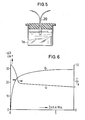
- FIG. 5 A suitable embodiment is shown in FIG. 5. It consists of a glass vessel (1a) with a lid in which the reflection light guide (20) is mounted. The vessel is stirred by a magnetic stirrer. The rest of the arrangement of the apparatus is the same as that described above in FIG. 2, ie the cuvette described there together with the storage vessel, pump and light guide is exchanged for the measuring vessel described in FIG. 5. The light intensity I ⁇ is measured. The light intensity before adding the demulsifier is called Io ⁇ . The extent of the coalescence can be estimated from the time course of the I ⁇ / Io ⁇ ratio.
- Curve a shows the measured values for the measurement of the light scattering by means of the reflection light guide
- curve b shows the values for the change in the light transmission, as they are obtained with a measuring cell according to FIG.
- an increase in light transmission correlates with a decrease in backscattered light. It can be seen that both measuring arrangements can be used to investigate the change in light scatter due to coalescence.
Landscapes
- Chemical & Material Sciences (AREA)
- Health & Medical Sciences (AREA)
- Life Sciences & Earth Sciences (AREA)
- Biochemistry (AREA)
- Engineering & Computer Science (AREA)
- Pathology (AREA)
- Immunology (AREA)
- General Physics & Mathematics (AREA)
- General Health & Medical Sciences (AREA)
- Physics & Mathematics (AREA)
- Analytical Chemistry (AREA)
- Oil, Petroleum & Natural Gas (AREA)
- Medicinal Chemistry (AREA)
- Food Science & Technology (AREA)
- General Chemical & Material Sciences (AREA)
- Chemical Kinetics & Catalysis (AREA)
- Investigating Or Analysing Materials By Optical Means (AREA)
- Optical Measuring Cells (AREA)
Abstract
Description
Für schwach streuende Flüssigkeiten sind Lichtstreumethoden sowohl theoretisch als auch apparativ sehr weit entwickelt. Sie ermöglichen Aussagen über die Größe und Form der dispergierten Partikel. Für die Vermessung von stark trüben Systemen sind dagegen in der Literatur nur wenige Arbeiten zu finden. Besondere Bedeutung hat die Messung der Lichtstreuung bei den stark trüben Rohölen, die Wasser-in-Öl Emulsionen darstellen. Bei herkömmlichen Messungen der Lichtstreuung bzw. Trübung verursacht die starke Lichtabsorption noch große Schwierigkeiten. Bei der Aufbereitung von Rohölen werden diese Emulsionen durch Zugabe eines sogenannten Spalters oder Demulgators gebrochen und so die Ölphase von der Wasserphase getrennt. Dieser Vorgang wird durch eine Koaleszenz der Wassertröpfchen eingeleitet und für die Bestimmung der Effektivität der verschiedenen Rohöl-Spalter istr es von Bedeutung, diese Koaleszenz in Rohölen nach Zugabe eines Spalters zu untersuchen.For weakly scattering liquids, light scattering methods are very well developed, both theoretically and in terms of equipment. They allow statements about the size and shape of the dispersed particles. On the other hand, only a few works can be found in the literature for the measurement of very cloudy systems. The measurement of light scattering is particularly important for the very cloudy crude oils, which are water-in-oil emulsions. With conventional measurements of light scattering or turbidity, the strong light absorption still causes great difficulties. When crude oils are processed, these emulsions are broken by adding a so-called splitter or demulsifier, thus separating the oil phase from the water phase. This process is initiated by a coalescence of the water droplets and to determine the effectiveness of the various crude oil splitters it is important to examine this coalescence in crude oils after adding a splitter.
Es wurde nun eine Vorrichtung gefunden, die es gestattet, solche Koaleszenzvorgänge in stark streuenden dispersen Systemen, insbesondere in Rohölemulsionen, mit Hilfe der Lichtstreuung zu untersuchen.A device has now been found which allows such coalescence processes in strongly scattering disperse systems, in particular in crude oil emulsions, to be investigated with the aid of light scattering.
Eine zur Durchführung dieser Messung geeignete Vorrichtung ist schematisch in Figur 1 dargestellt. Sie besteht im wesentlichen aus einer Küvette aus Glas (1), einer Lichtquelle (2) und einem Lichtdetektor (3). Von der Lichtquelle und dem Lichtdetektor gehen Lichtleiter (4) und (5) aus, deren Enden auf zwei gegenüberliegenden Flächen der Küvette aufliegen. Die Enden der Lichtleiter stehen sich genau gegenüber.A device suitable for carrying out this measurement is shown schematically in FIG. 1. It essentially consists of a glass cuvette (1), a light source (2) and a light detector (3). Light guides (4) and (5) extend from the light source and the light detector, the ends of which rest on two opposite surfaces of the cuvette. The ends of the light guides face each other exactly.
Eine bevorzugte Ausführungsform hierzu ist in Figur 2 dar gestellt. Die Glasküvette (1) ist über die Pumpe (6) mit einem Vorratsgefäß (7) verbunden, in dem sich die zu untersuchende Emulsion befindet und in das der zu untersuchende Spalter gegeben werden kann. Zweckmäßigerweise wird dieses Vorratsgefäß durch hier nicht dargestellte Heiz- und Kühlvorrichtungen und mittels eines Thermostats auf konstanter Temperatur gehalten. Außerdem ist das Vorratsgefäß noch mit einem Rührer versehen. Auf der einen Seite der Küvette (1) liegt das Ende eines Lichtleiters (4) auf, der von der Lichtquelle (2), hier ein He-Ne-Laser mit einer Leistung von 5 milli-Watt, ausgeht. Auf der gegenüberliegenden Seite der Küvette, genau gegenüber dem Endpunkt des von der Lichtquelle ausgehenden Lichtleiters liegt das Ende eines zweiten Lichtleiters (5) auf, der zu einem Photomultiplier (3) führt, der als Lichtdetektor fungiert. Die Küvette selbst hat eine Dicke von ca. 0,3 bis 3 mm, vorzugsweise 1 mm. Zweckmäßigerweise befindet sich zwischen Küvette und Photomultiplier ein Interferenzfilter (8), durch das ein Einfluß von Fremdlicht vermieden werden soll. Gegebenenfalls kann man diesen Interferenzfilter auch mit einem Graufilter kombinieren, wenn die Intersität des aus der Küvette austretenden Lichts zu groß ist für den Lichtdetektor. Der Unterdrückung des Fremdlichts dient auch die Kombination von Chopper (9) und Lock-in Verstärker (10), wobei der Chopper zwischen Laser (2) und Glasküvette (1) und der Lock-in Verstärker am Ausgang des Photomultipliers angeordnet ist. Das am Lock-in Verstärker erhaltene Meßsignal wird durch einen Rechner (11) und Schreiber (12) ausgewertet.A preferred embodiment for this is shown in FIG. 2 posed. The glass cuvette (1) is connected via the pump (6) to a storage vessel (7) in which the emulsion to be examined is located and into which the splitter to be examined can be placed. This storage vessel is expediently kept at a constant temperature by heating and cooling devices (not shown here) and by means of a thermostat. In addition, the storage vessel is also provided with a stirrer. On one side of the cuvette (1) lies the end of a light guide (4) which starts from the light source (2), here a He-Ne laser with a power of 5 milli-watts. On the opposite side of the cuvette, exactly opposite the end point of the light guide emanating from the light source, there is the end of a second light guide (5) which leads to a photomultiplier (3) which functions as a light detector. The cuvette itself has a thickness of approximately 0.3 to 3 mm, preferably 1 mm. An interference filter (8) is expediently located between the cuvette and the photomultiplier, by means of which an influence of extraneous light is to be avoided. If necessary, this interference filter can also be combined with a gray filter if the intensity of the light emerging from the cuvette is too great for the light detector. The combination of chopper (9) and lock-in amplifier (10) also serves to suppress the extraneous light, the chopper being arranged between the laser (2) and the glass cuvette (1) and the lock-in amplifier at the output of the photomultiplier. The measurement signal obtained at the lock-in amplifier is evaluated by a computer (11) and recorder (12).
Eine andere Ausführungsform für eine geeignete Meßzelle ist in Figur 3 und 3a dargestellt. Sie besteht aus einem unter konisch geschlossenen Glasgefäß (1a) mit zwei kreisförmigen, sich horizontal gegenüberliegenden Öffnungen (13) und (14), zwei in diesen Öffnungen eingelagerten zylinderförmigen Halterungen (15) und (16), die jeweils in ihrer Achse einen Lichtleiter (4) bzw. (5) tragen, wobei die beiden sich gegenüberliegenden Enden dieser Halterungen in geeigneter Weise starr überbrückt sind, so daß die Enden der beiden Lichtleiter genau gegenüberstehen. Die sich gegenüberliegenden Enden der beiden Halterungen sind am einfachsten durch ein oder mehrere fest montierte Stege (17) oder auf andere Weise starr miteinander verbunden, damit die beiden Enden der Lichtleiter im gewünschten Abstand voneinander fest in ihrer Position fixiert werden. Dieser Abstand der beiden Lichtleiter soll ca. 0,3 bis 3 mm betragen. Die beiden Halterungen für die Lichtleiter werden in den Öffnungen (13) und (14) durch aufgeschraubte Kappen (18) und (19) festgehalten. Die beiden Öffnungen (13) und (14) sind vorzugsweise so angeordnet, wie aus Figur 3a hervorgeht, d.h. die Mittelachse der Öffnungen (13) und (14) ist auf der horizontalen Schnittebene etwas seitlich verschoben, so daß Raum bleibt für einen von oben in die Meßzelle eingeführten Rührer. Die übrige Anordnung der Apparaur ist die gleiche wie oben bei Figur 2 beschrieben, d.h. die dort beschriebene Küvette mitsamt dem Vorratsgefäß und Pumpe für die zu messende Flüssigkeit wird gegen die in Figur 3 beschriebene Meßzelle ausgetauscht.Another embodiment for a suitable measuring cell is shown in FIGS. 3 and 3a. It consists of a conically closed glass vessel (1a) with two circular, horizontally opposite openings (13) and (14), two cylindrical holders (15) and (16) embedded in these openings, each with an optical fiber in its axis ( Wear 4) or (5), the the two opposite ends of these brackets are suitably rigidly bridged so that the ends of the two light guides are exactly opposite. The opposite ends of the two brackets are most simply rigidly connected to one another by one or more fixed webs (17) or in some other way, so that the two ends of the light guides are firmly fixed in position at the desired distance from one another. This distance between the two light guides should be approx. 0.3 to 3 mm. The two holders for the light guides are held in the openings (13) and (14) by screwed caps (18) and (19). The two openings (13) and (14) are preferably arranged as shown in FIG. 3a, ie the central axis of the openings (13) and (14) is shifted somewhat laterally on the horizontal sectional plane, so that space remains for one from above stirrer inserted into the measuring cell. The rest of the arrangement of the apparatus is the same as described above in FIG. 2, ie the cuvette described there, together with the storage vessel and pump for the liquid to be measured, is exchanged for the measuring cell described in FIG. 3.
Bei all diesen Anordnungen wird das in die Meßzelle eingestrahlte Licht in dem dispersen Medium gestreut und aus der Abschwächung des Meßsignals wird die effektive optische Dichte D gemäß der Formel D = log ![]()
![]()
Man kann die Lichtstreuung auch über das rückwärts ge streute Licht messen. Dies geschieht zweckmäßigerweise mit einem Reflexlichtleiter, dessen Sender- und Empfängerfasern statistisch gemischt sind. Eine geeignete Ausführungsform ist in Figur 5 dargestellt. Sie besteht aus einem Glasgefäß (1a) mit einem Deckel, in dem der Reflexlichtleiter (20) montiert ist. Das Gefäß wird durch einen Magnetrührer gerührt. Die übrige Anordnung der Apparatur ist die gleiche wie oben bei Figur 2 beschrieben, d.h. die dort beschriebene Küvette mitsamt dem Vorratsgefäß, Pumpe und Lichtleiter wird gegen das in Figur 5 beschriebene Meßgefäß ausgetauscht. Gemessen wird die Lichtintensität Iʹ. Die Lichtintensität vor Zugabe des Demulgators wird mit Ioʹ bezeichnet. Das Ausmaß der Koaleszenz kann durch den zeitlichen Verlauf des Verhältnisses Iʹ/Ioʹ abgeschätzt werden.You can also use the backward light scattering measure scattered light. This is expediently done with a reflection light guide, the transmitter and receiver fibers of which are statistically mixed. A suitable embodiment is shown in FIG. 5. It consists of a glass vessel (1a) with a lid in which the reflection light guide (20) is mounted. The vessel is stirred by a magnetic stirrer. The rest of the arrangement of the apparatus is the same as that described above in FIG. 2, ie the cuvette described there together with the storage vessel, pump and light guide is exchanged for the measuring vessel described in FIG. 5. The light intensity Iʹ is measured. The light intensity before adding the demulsifier is called Ioʹ. The extent of the coalescence can be estimated from the time course of the Iʹ / Ioʹ ratio.
In einer Apparatur wie in Figur 2 dargestellt, wurde die Koaleszenzwirkung unterschiedlicher Mengen eines Propylenoxid-Ethylenoxid-Blockpolymers auf der Basis eines Propylenoxids mit einem Molgewicht von 2000, umgesetzt mit 38 % Ethylenoxid, bei einer Emulsion bestehend aus 82 % Rohöl aus Norddeutschland und 18 % Wasser untersucht. Die Temperatur betrug 40°C. Der Demulgator wurde als verdünnte Lösung in Xylol zu der Zeit t = 0 zudosiert. Wie in Fig. 4 zu sehen, zeigt sich schon nach wenigen Sekunden eine Zunahme der Lichtdurchlässigkeit bzw. eine Abnahme der effektiven optischen Dichte -ΔD infolge der Koaleszenz. Mit zunehmenden Mengen an Demulgator beobachtet man eine stärkere Koaleszenz.In an apparatus as shown in Figure 2, the coalescence effect of different amounts of a propylene oxide-ethylene oxide block polymer based on a propylene oxide with a molecular weight of 2000, reacted with 38% ethylene oxide, in an emulsion consisting of 82% crude oil from northern Germany and 18% Examined water. The temperature was 40 ° C. The demulsifier was metered in as a dilute solution in xylene at the time t = 0. As can be seen in FIG. 4, an increase in the light transmittance or a decrease in the effective optical density -ΔD due to the coalescence can be seen after only a few seconds. With increasing amounts of demulsifier a stronger coalescence is observed.
Die Untersuchung der Koaleszenz durch Messung des rückwärts gerichteten Lichts und durch Lichtabschwächung wurden verglichen. Für die Messungen der Lichtabschwächung wurde eine Meßzelle wie in Figur 3 benutzt, für die Messungen aus rückwärts gestreutem Licht eine Anordnung wie in Figur 5 benutzt, Die Emulsion bestand aus gleichen Anteilen wasserfreiem süddeutschem Rohöl und 0,5 % NaCl-Lösung. Der Demulgator war ein oxethyliertes Alkylphenolformaldehydharz; es wurden 40 ppm des Demulgators als verdünnte Lösung in Xylol zudosiert. Die Ergebnisse sind in Figur 6 dargestellt. Kurve a zeigt die Meßwerte für die Messung der Lichtstreuung mittels des Reflexlichtleiters, Kurve b zeigt die Werte, für die Änderung der Lichtdeurchlässigkeit, wie sie mit einer Meßzelle nach Figur 3 erhalten werden. Wie erwartet korreliert eine Zunahme der Lichtdurchlässigkeit mit einer Abnahme des rückwärts gestreuten Lichtes. Man sieht, daß beide Meßanordnungen benutzt werden können, um die Änderung der Lichtstreuung infolge Koaleszenz zu untersuchen.The study of coalescence by measuring backward light and by light attenuation were compared. For measurements of light attenuation a measuring cell as in FIG. 3 was used, for the measurements from backscattered light an arrangement as in FIG. 5 was used. The emulsion consisted of equal parts of anhydrous southern German crude oil and 0.5% NaCl solution. The demulsifier was an ethoxylated alkylphenol formaldehyde resin; 40 ppm of the demulsifier were metered in as a dilute solution in xylene. The results are shown in Figure 6. Curve a shows the measured values for the measurement of the light scattering by means of the reflection light guide, curve b shows the values for the change in the light transmission, as they are obtained with a measuring cell according to FIG. As expected, an increase in light transmission correlates with a decrease in backscattered light. It can be seen that both measuring arrangements can be used to investigate the change in light scatter due to coalescence.
Claims (4)
Applications Claiming Priority (2)
| Application Number | Priority Date | Filing Date | Title |
|---|---|---|---|
| DE3615222 | 1986-05-06 | ||
| DE19863615222 DE3615222A1 (en) | 1986-05-06 | 1986-05-06 | DEVICE FOR MEASURING THE LIGHT DISTRIBUTION IN STRONG DISTRIBUTING SYSTEMS |
Publications (1)
| Publication Number | Publication Date |
|---|---|
| EP0244789A2 true EP0244789A2 (en) | 1987-11-11 |
Family
ID=6300233
Family Applications (1)
| Application Number | Title | Priority Date | Filing Date |
|---|---|---|---|
| EP19870106383 Withdrawn EP0244789A2 (en) | 1986-05-06 | 1987-05-02 | Device for the measurement of light scattering in strongly scattering disperse media |
Country Status (2)
| Country | Link |
|---|---|
| EP (1) | EP0244789A2 (en) |
| DE (1) | DE3615222A1 (en) |
Cited By (1)
| Publication number | Priority date | Publication date | Assignee | Title |
|---|---|---|---|---|
| FR2643147A1 (en) * | 1989-02-14 | 1990-08-17 | Malifaud Pierre | Method for spectrophotometric analysis of a fluid, in particular in a dangerous area using a cell with an integrated high-energy source, and optical device making use thereof |
Families Citing this family (1)
| Publication number | Priority date | Publication date | Assignee | Title |
|---|---|---|---|---|
| DE19717287C1 (en) * | 1997-04-24 | 1998-10-01 | Hydac Filtertechnik Gmbh | Arrangement for measuring the turbidity of a fluid |
-
1986
- 1986-05-06 DE DE19863615222 patent/DE3615222A1/en not_active Withdrawn
-
1987
- 1987-05-02 EP EP19870106383 patent/EP0244789A2/en not_active Withdrawn
Cited By (1)
| Publication number | Priority date | Publication date | Assignee | Title |
|---|---|---|---|---|
| FR2643147A1 (en) * | 1989-02-14 | 1990-08-17 | Malifaud Pierre | Method for spectrophotometric analysis of a fluid, in particular in a dangerous area using a cell with an integrated high-energy source, and optical device making use thereof |
Also Published As
| Publication number | Publication date |
|---|---|
| DE3615222A1 (en) | 1987-11-12 |
Similar Documents
| Publication | Publication Date | Title |
|---|---|---|
| DE3103476C2 (en) | ||
| DE69116041T2 (en) | Apparatus and method for detecting gas present in a downhole liquid flow | |
| DE3688380T2 (en) | METHOD FOR MEASURING THE LIGHT ABSORPTION CAPACITY OF A LIQUID MEDIUM. | |
| DE68927097T2 (en) | DIFFERENTIAL REFRACTOMETER | |
| DE69228550T2 (en) | MEASURING METHOD AND DEVICE | |
| DE69012837T2 (en) | MEASURING DEVICE. | |
| DE2446032A1 (en) | METHOD AND DEVICE FOR DETERMINING SUBMICROMETRICALLY SIZED PARTICLES | |
| EP0144713A2 (en) | Device for optically measuring concentration of substances | |
| DE2907000A1 (en) | NEPHELOMETER | |
| DE2537712A1 (en) | DEVICE FOR MEASURING THE CONCENTRATION OF PARTICULARS IN A LIQUID | |
| DE112008003610T5 (en) | Pass-fail tool to test the level of contamination by particles in a fluid | |
| DE2621217C2 (en) | ||
| DE69026448T2 (en) | Improvement in weakened total reflection spectroscopy | |
| DE4031320A1 (en) | Optical body fluid or tissue examination device - evaluates intensity or spectral variation between incident and diffused light | |
| EP0244789A2 (en) | Device for the measurement of light scattering in strongly scattering disperse media | |
| DE3324606A1 (en) | Apparatus for measuring and determining the nitrate content of liquids | |
| DE3706458C2 (en) | ||
| EP3136083B1 (en) | Method and device for determining a substance or the concentration of a substance in a fluid medium | |
| DE3319922C2 (en) | ||
| CH442805A (en) | Method and device for measuring and registering the absorption of electromagnetic radiation | |
| DE3212219A1 (en) | FLUORESCENCE SPECTROPHOTOMETER | |
| DE3821543C2 (en) | ||
| DE19755589A1 (en) | Measurement apparatus for 3-dimensional cross correlation techniques for exact determination of hydrodynamic diameter of particles suspended in fluid and of scattering cross-section | |
| DE3024061A1 (en) | REFRACTOMETER | |
| DE19631423B4 (en) | Method for spatially resolved substance detection |
Legal Events
| Date | Code | Title | Description |
|---|---|---|---|
| PUAI | Public reference made under article 153(3) epc to a published international application that has entered the european phase |
Free format text: ORIGINAL CODE: 0009012 |
|
| AK | Designated contracting states |
Kind code of ref document: A2 Designated state(s): BE CH DE FR GB LI NL |
|
| STAA | Information on the status of an ep patent application or granted ep patent |
Free format text: STATUS: THE APPLICATION HAS BEEN WITHDRAWN |
|
| 18W | Application withdrawn |
Withdrawal date: 19890613 |
|
| R18W | Application withdrawn (corrected) |
Effective date: 19890613 |
|
| GBT | Gb: translation of ep patent filed (gb section 77(6)(a)/1977) | ||
| GBT | Gb: translation of ep patent filed (gb section 77(6)(a)/1977) |
Free format text: FOR 0244789 READ 0224789 IN JOURNAL 5247 PAGE 3574 |
|
| RIN1 | Information on inventor provided before grant (corrected) |
Inventor name: MILLER, DENNIS, DR. |