EP0244779B1 - Adaptive depolarization interference compensator - Google Patents
Adaptive depolarization interference compensator Download PDFInfo
- Publication number
- EP0244779B1 EP0244779B1 EP87106326A EP87106326A EP0244779B1 EP 0244779 B1 EP0244779 B1 EP 0244779B1 EP 87106326 A EP87106326 A EP 87106326A EP 87106326 A EP87106326 A EP 87106326A EP 0244779 B1 EP0244779 B1 EP 0244779B1
- Authority
- EP
- European Patent Office
- Prior art keywords
- signal
- polarisation
- interference
- polarization
- transversal
- Prior art date
- Legal status (The legal status is an assumption and is not a legal conclusion. Google has not performed a legal analysis and makes no representation as to the accuracy of the status listed.)
- Expired - Lifetime
Links
Images


Classifications
-
- H—ELECTRICITY
- H04—ELECTRIC COMMUNICATION TECHNIQUE
- H04B—TRANSMISSION
- H04B7/00—Radio transmission systems, i.e. using radiation field
- H04B7/002—Reducing depolarization effects
Definitions
- the invention relates to an adaptive depolarization interference compensator for digital radio relay systems with multi-stage quadrature amplitude modulation (QAM) with synchronous channel operation of the orthogonally polarized signals which is not necessarily synchronous with regard to clock and / or carrier frequency using transversal filters with devices for decoupling signals from the receiving branch one polarization and coupling into the reception path of the other polarization, with a quadrature demodulator arranged in the reception branch of the two receivers with the same or with synchronized separate local oscillators for the differently polarized signals for its two signal components (I and Q channel) and also a canceller , which consists of two complex transversal filters for the two polarization directions, each of which is supplied with an IF received signal of polarization on the input side, and the output side in the Receiving branch of the other polarization are coupled.
- QAM quadrature amplitude modulation
- both polarization directions vertical and horizontal
- both orthogonal polarization directions and co-channel operation the bandwidth efficiency increases by about Factor 2.
- the susceptibility to interference due to depolarization effects increases significantly. Depolarization occurs when there is rain, snow and multipath propagation.
- frequency-selective depolarization occurs in cooperation with the antenna characteristics for both polarization directions, especially in the case of deep dispersive fading.
- the main effects for depolarization depend on propagation conditions, which are of course time-varying.
- cancellers consisting of crosswise arranged adaptive phase rotators with an AGC are provided between the two receiving channels. This reduces the coupling of the two channels caused by depolarization.
- This arrangement can be implemented in the RF range, IF range or baseband. The effect of frequency selective depolarization is only limited. An arrangement of this kind is known from the essay "A decision-directed network for dual-polarization crosstalk cancellation" by William J. Weber, published in ICC79, 40.4.1 to 40.4.7.
- a compensator of the type described in the opening paragraph is known from IEEE International Conference on Communications, Proceedings, Volume 3, May 1984, pages 1442-1446.
- a compensator of a similar design is known from IEEE International Conference on Communications, Proceedings, Volume 3, June 1981, pages 46.3.1 - 46.3.5.
- transversal filters are used as cancellers either in the IF level or in the baseband. These are so-called baud-spaced transversal filters, ie the runtime between two successive taps is one symbol period.
- baud-spaced transversal filters ie the runtime between two successive taps is one symbol period.
- cancellers are not particularly suitable for non-synchronous clocks in the data streams of both polarization directions.
- the transversal filter is essentially set using two algorithms, namely the zero-forcing algorithm and the minimum mean square error algorithm (MMSE). Both algorithms work with samples of the multistage baseband signals. This also shows that the setting of the filter depends on the clock phase. The clock of the interfering signal must be used in each case to set the cancel quadripole in order to achieve a stable setting of the coefficients.
- the zero-forcing algorithm brings about an exact match of the compensation signal with the interference signal at many sampling times corresponding to the filter length (number of coefficients).
- the MMSE algorithm leads to a minimal mean square error between the compensation and interference signal at all sampling times. In the case of asynchronous clock cycles, however, the sampling time of the interference signal generally does not match the sampling time of the useful signal.
- the sampling values in the symbol clock interval do not meet the sampling theorem with realizable Nyquist pulse shaping.
- the canceller is set according to the zero-forcing algorithm, which can be seen at the zeros of the residual interference according to the filter length.
- the residual interference between the sampling times is relatively large.
- the invention has for its object to provide an adaptive depolarization interference compensator with which, even with asynchronous co-channel operation, ie also between the sampling times of the differently polarized signals, good compensation of depolarization effects is achieved.
- FIG. 1 shows a radio relay system with an adaptive compensator in a simplified representation.
- transmitters 1, 2 for the vertical polarization and the horizontal polarization are arranged on the transmission side on which no synchronization of the carriers is assumed.
- the associated receivers (Receiver Rx) on the receiving side are labeled 3 and 4.
- the RF local oscillators of the receivers 3, 4 must be synchronized. As shown in the exemplary embodiment shown, this can also be achieved in that a common local oscillator 5 is provided for both receivers 3, 4. Due to depolarization effects, interference occurs in the radio field one polarization into the received signal of the other polarization. This is shown in the figure by the intersecting arrows labeled S HV and S VH , which means that signal parts of the horizontal polarization reach the vertical polarization reception path and vice versa.
- reception filters 6.7 and quadrature demodulators 8.14 follow, each of which is connected to a local oscillator VCO 9.15.
- the demodulators 8, 14 are each followed in the reception path of the individual signals (I and Q channel) by a complex baseband transversal filter 10, 11 and 16, 17 provided for equalization, which on the output side is connected to a summing element 12, 13 and 18 , 19 are connected.
- the baseband transversal filters are not absolutely necessary.
- the actual canceller is shown in the center of the picture between the two reception branches with the quadrature demodulators 8, 14 and baseband transversal filters 10, 11 and 16, 17, which consists of two quadrature demodulators 20, 23 for the two polarization directions, each of which receives a polarization reception signal on the input side and the IF carrier of the respective other polarization is fed, as well as from each of a complex transversal filter (I and Q channel) 21, 22 and 24.25 in the signal paths after the two quadrature demodulators 20.23, the output side in the receiving branch of the each other polarization are coupled.
- the output of the relevant transversal filters 21, 22 and 24, 25 is connected to the corresponding summing element 12, 13 and 18, 19 in the relevant reception branches.
- the summation elements 12, 13 and 18, 19 can also immediately follow up with an upstream runtime compensation (compensates for signal runtime through the transversal filter of the Canceller) the quadrature demodulators 8, 14 can be arranged.
- the transit time between the taps of the transversal filters 21, 22 and 24.25 corresponds at most to half the reciprocal of the frequency of the highest spectral component of the baseband signal (fulfillment of the sampling theorem).
- a rational ratio m / n is advantageously chosen, which delivers a shorter or the same runtime.
- m and n are integers.
- the value m / n 2 was chosen. Further details on the setting of the transverse filters 21, 22 and 24, 25 provided for the compensation are given in the further description of the figures below.
- FIG. 2 shows the structure of a complex T / 2 transversal filter which, for the sake of simplicity, is drawn as a symmetrical 5-tap transversal filter in a parallel-in-serial-out structure.
- This transversal filter with the inputs x I and x Q and the outputs y I and y Q is a detailed illustration of the transversal filter 21, 22 in FIG. 1, the connection terminals of which are provided with the corresponding designations.
- Such a complex arrangement, provided for a QAM system, with an I and a Q channel contains equalizers of identical design in both channels.
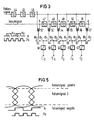
- FIG. 3 shows a partial representation, ie 1/4 of the overall arrangement for a 5-tap transversal filter.
- An error signal and a main signal are required for the correlation, the error signal being obtained from the sampling of the disturbed received signal at the frequency corresponding to the reciprocal of the delay of a delay element in the transversal filter of the Canceller, and the main signal being a signal representing the interfering transmission sequence, which is derived from the Received signal of the other polarization is derived (a circuit for deriving these signals is shown in Fig. 6).
- the error signal and gas main signal are time-shifted via a delay element 44 ...
- the changeover switches are switched in the rhythm of half the symbol period, that is to say with the double clock frequency 2f S , so that they are applied to adjacent integrators during clock phases of the same length ⁇ 1 and ⁇ 2.
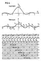
- FIG. 4 shows the mode of operation of the circuit described above, the principle of the correlator being shown for the sake of simplicity only for the single-channel case.
- an error signal is recorded with the sample values e-6; e-5, e-4 ... eo ... e4, e5, e6 at times -3T to + 3T.
- the transmission sequence of the main signal is delivered to the correlator at the speed of the symbol clock f S , but the error samples are supplied with the double symbol clock 2f S.
- This is shown graphically in the diagrams below. Below this, the samples at various taps of the correlator are drawn in the diagrams a to g, the individual letters a to g of the diagrams being assigned to the correspondingly labeled taps in the correlator according to FIG. 3. It is clear from these time diagrams of the correlator that two error samples reach the same multiplier during a symbol period, which cause the filter setting for two adjacent coefficients of the T / 2 transversal filter. This means that the results of the multiplier with the double symbol clock must be connected to the corresponding inputs of the integrators.
- the error signal can be determined in the manner shown in FIG. 5 using the example of a 16 QAM signal.
- Two thresholds are formed for determining the error signal, which are based on the two highest-level signal values, i.e. the largest or outermost positive and negative amplitude level. The following applies: if the sampled signal is greater than the upper threshold, then the error contribution is positive; if the sample is smaller than the most negative level, the error contribution is negative. However, if the sample lies in between, the error contribution is zero, which leads to no correlation information.
- This evaluation of the sampled values has the advantage over a single threshold in the middle that, in the case of synchronous data streams, the one scan of the error bit, which coincides with the center of the eye of the disturbed useful signal, also provides correlation information for small disturbances.
- the main signal that causes the depolarization disturbances is now important for the correlation.
- This signal is already available, but it has been demodulated with another carrier with regard to the error samples.
- the signal causing the depolarization disturbance with the complex differential pointer is therefore used for the correlation multiplied the carrier frequencies of the two polarizations.
- the main signal required for the correlation can then be obtained by sampling.
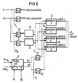
- a circuit which carries out the derivation of the error signal and the aforementioned multiplication of the main signal, that is to say generates the input signals for correlator control, is shown for one side of the canceller in FIG. 6. This circuit eliminates interference in the H channel in the V channel.
- signal parts are decoupled from the I and Q channels of the vertically polarized signal, and are passed via an A / D converter 69, 70 to error signal evaluations 71, 72, the outputs of which each have two correlators 73, 75 and 74, 76 of the type described in Figures 4 and 7 are connected. Furthermore, signal parts of the I and Q channels of the horizontally polarized signal are fed to a multiplier 77 and multiplied in this by the difference rotary pointer of the carrier frequencies f VCOH and f VCOV of the non-synchronous carriers of the two polarizations.
- the output signals HI ⁇ and HQ ⁇ of the multiplier 77 reach the second input of the correlators 73, 74 and 75, 76 via A / D converters 78, 79.
- These correlators provide the setting variables for the actuators a, b, c and d im Transversal filter according to Figure 2. This is indicated by the designation "control" on the corresponding arrows in Figures 2 and 6.
- the multiplication can of course also take place after the A / D converters.
- FIG. 8 shows, as already explained above, diagrams of the interference signal, the compensation signal and the remaining interference for a simple baseband model with selective depolarization interference for a canceller, consisting of a 7-tap baud-spaced transversal filter.
- a canceller whose transversal filter has a running time between the taps of for example, have half a symbol period (T / 2).
- T / 2 half a symbol period
Abstract
Description
Die Erfindung bezieht sich auf einen adaptiven Depolarisations-Interferenz-Kompensator für digitale Richtfunksysteme mit vielstufiger Quadraturamplitudenmodulation (QAM) bei hinsichtlich Takt- und/oder Trägerfrequenz nicht notwendigerweise synchronem Gleichkanalbetrieb der orthogonal polarisierten Signale unter Verwendung von Transversalfiltern mit Einrichtungen zur Auskopplung von Signalen aus dem Empfangszweig der einen Polarisation und Einkopplung in den Empfangsweg der jeweils anderen Polarisation, mit im Empfangszweig der beiden Empfänger mit demselben oder mit aufeinander synchronisierten getrennten Lokaloszillatoren für die unterschiedlich polarisierten Signale angeordnetem Quadraturdemodulator für seine beiden Signalanteile (I- und Q-Kanal) und ferner einem Canceller, der aus zwei komplexen Transversalfiltern für die beiden Polarisationsrichtungen besteht, denen eingangsseitig jeweils ein ZF-Empfangssignal einer Polarisation zugeführt wird, und die ausgangsseitig in den Empfangszweig der jeweils anderen Polarisation eingekoppelt werden.The invention relates to an adaptive depolarization interference compensator for digital radio relay systems with multi-stage quadrature amplitude modulation (QAM) with synchronous channel operation of the orthogonally polarized signals which is not necessarily synchronous with regard to clock and / or carrier frequency using transversal filters with devices for decoupling signals from the receiving branch one polarization and coupling into the reception path of the other polarization, with a quadrature demodulator arranged in the reception branch of the two receivers with the same or with synchronized separate local oscillators for the differently polarized signals for its two signal components (I and Q channel) and also a canceller , which consists of two complex transversal filters for the two polarization directions, each of which is supplied with an IF received signal of polarization on the input side, and the output side in the Receiving branch of the other polarization are coupled.
Zur Erhöhung der Bandbreiteneffizienz bei Digitalrichtfunksystemen mit vielstufiger Quadraturamplitudenmodulation (16 QAM, 64 QAM, ...) bietet es sich an, in einem Kanal gleichzeitig beide Polarisationsrichtungen zu benutzen. Die bislang übliche Nutzung beider Polarisationsrichtungen (vertikal und horizontal) beschränkt sich darauf, benachbarte Kanäle orthogonal polarisiert auszusenden, um durch die Polarisationsentkopplung die Nachbarkanalstörungen soweit zu reduzieren, daß zumindest eine teilweise Überlappung von Nachbarspektren möglich ist. Durch die Nutzung beider orthogonaler Polarisationsrichtungen und Gleichkanalbetrieb erhöht sich die Bandbreiteneffizienz etwa um den Faktor 2. Jedoch wird die Störanfälligkeit durch Depolarisationseffekte wesentlich größer. Depolarisation tritt u.a. bei Regen, Schnee und Mehrwegeausbreitung auf. Bei Mehrwegeausbreitung tritt im Zusammenwirken mit den Antennencharakteristiken für beide Polarisationsrichtungen vor allem bei tiefem dispersiven Fading frequenzselektive Depolarisation auf. Die Haupteffekte für die Depolarisation sind von Ausbreitungsbedingungen abhängig, die natürlich zeitvariant sind.To increase the bandwidth efficiency in digital radio relay systems with multi-stage quadrature amplitude modulation (16 QAM, 64 QAM, ...) it makes sense to use both polarization directions in one channel at the same time. The usual use of both polarization directions (vertical and horizontal) is limited to transmitting neighboring channels orthogonally polarized in order to reduce the adjacent channel interference by the polarization decoupling to such an extent that at least a partial overlap of neighboring spectra is possible. By using both orthogonal polarization directions and co-channel operation, the bandwidth efficiency increases by about
Zur Kompensation solcher Depolarisationseffekte sind sog. Canceller aus kreuzweise angeordneten adaptiven Phasendrehern mit einer AGC zwischen den beiden Empfangskanälen vorgesehen. Dadurch wird die durch Depolarisation hervorgerufene Verkopplung beider Kanäle reduziert. Diese Anordnung kann im RF-Bereich, ZF-Bereich oder Basisband realisiert werden. Die Wirkung bei frequenzselektiver Depolarisation ist allerdings nur begrenzt. Eine Anordnung dieser Art ist durch den Aufsatz "A decision-directed network for dual-polarization crosstalk cancellation" von William J. Weber, erschienen in ICC79, 40.4.1 bis 40.4.7, bekannt.To compensate for such depolarization effects, so-called cancellers consisting of crosswise arranged adaptive phase rotators with an AGC are provided between the two receiving channels. This reduces the coupling of the two channels caused by depolarization. This arrangement can be implemented in the RF range, IF range or baseband. The effect of frequency selective depolarization is only limited. An arrangement of this kind is known from the essay "A decision-directed network for dual-polarization crosstalk cancellation" by William J. Weber, published in ICC79, 40.4.1 to 40.4.7.
Ein Kompensator der eingangs beschriebenen Art ist aus IEEE International Conference on Communications, Proceedings, Band 3, Mai 1984, Seiten 1442 - 1446 bekannt. Aus IEEE International Conference on Communications, Proceedings, Band 3, Juni 1981, Seiten 46.3.1 - 46.3.5 ist ein ähnlich aufgebauter Kompensator bekannt.A compensator of the type described in the opening paragraph is known from IEEE International Conference on Communications, Proceedings,
Für eine bessere Kompensation der frequenzselektiven Depolarisation werden Transversalfilter als Canceller entweder in der ZF-Ebene oder im Basisband verwendet. Dabei handelt es sich um sog. Baudspaced-Transversalfilter, d.h. die Laufzeit zwischen zwei aufeinanderfolgenden Abgriffen beträgt eine Symbolperiode. Solche Canceller sind jedoch vor allem bei nicht synchronen Takten der Datenströme beider Polarisationsrichtungen wenig geeignet.For better compensation of frequency-selective depolarization, transversal filters are used as cancellers either in the IF level or in the baseband. These are so-called baud-spaced transversal filters, ie the runtime between two successive taps is one symbol period. However, such cancellers are not particularly suitable for non-synchronous clocks in the data streams of both polarization directions.
Die Einstellung der Transversalfilter erfolgt im wesentlichen durch zwei Algorithmen, nämlich den Zero-Forcing-Algorithmus und den Minimum-Mean-Square-Error-Algorithmus (MMSE). Beide Algorithmen arbeiten mit Abtastwerten der mehrstufigen Basisbandsignale. Damit ist auch ersichtlich, daß die Einstellung der Filter abhängig von der Taktphase ist. Für die Einstellung des Cancelvierpols muß jeweils der Takt des störenden Signals verwendet werden, um eine stabile Einstellung der Koeffizienten zu erreichen. Der Zero-Forcing-Algorithmus bewirkt eine genaue Übereinstimmung des Kompensationssignals mit dem Störsignal an entsprechend der Filterlänge (Koeffizientenanzahl) vielen Abtastzeitpunkten. Der MMSE-Algorithmus führt zu einem minimalen mittleren quadratischen Fehler zwischen Kompensations- und Störsignal zu allen Abtastzeitpunkten. Bei asynchronen Takten stimmt nun aber der Abtastzeitpunkt des Störsignals im allgemeinen nicht mit dem Abtastzeitpunkt des Nutzsignals überein. Bei einem Baudspaced-Transversalfilter erfüllen also die Abtastwerte im Symboltaktabstand bei realisierbarer Nyquist-Pulsformung nicht das Abtasttheorem. Damit ist die Übereinstimmung des Kompensations- mit dem Störsignal außerhalb der für die Gewinnung der Stellspannungen benutzten Abtastzeitpunkte nicht sehr gut (vgl. hierzu Figur 8, in der für ein einfaches Basisbandmodell mit selektiver Depolarisationsstörung in einem ersten Diagramm das Störsignal und das Kompensationssignal und in einem zweiten Diagramm die übriggebliebene Reststörung für einen Canceller, bestehend aus einem 7Tap-Baudspaced-Transversalfilter, dargestellt ist). Der Canceller ist hierbei nach dem Zero-Forcing-Algorithmus eingestellt, was ersichtlich ist an den Nullstellen der Reststörung entsprechend der Filterlänge. Zwischen den Abtastzeitpunkten ist die Reststörung relativ groß.The transversal filter is essentially set using two algorithms, namely the zero-forcing algorithm and the minimum mean square error algorithm (MMSE). Both algorithms work with samples of the multistage baseband signals. This also shows that the setting of the filter depends on the clock phase. The clock of the interfering signal must be used in each case to set the cancel quadripole in order to achieve a stable setting of the coefficients. The zero-forcing algorithm brings about an exact match of the compensation signal with the interference signal at many sampling times corresponding to the filter length (number of coefficients). The MMSE algorithm leads to a minimal mean square error between the compensation and interference signal at all sampling times. In the case of asynchronous clock cycles, however, the sampling time of the interference signal generally does not match the sampling time of the useful signal. In the case of a baud-spaced transversal filter, the sampling values in the symbol clock interval do not meet the sampling theorem with realizable Nyquist pulse shaping. This means that the agreement of the compensation signal with the interference signal outside the sampling times used to obtain the control voltages is not very good (see FIG. 8, in which, for a simple baseband model with selective depolarization interference, the interference signal and the compensation signal in a first diagram and in one second diagram shows the residual interference for a canceller consisting of a 7-tap baud-spaced transversal filter). The canceller is set according to the zero-forcing algorithm, which can be seen at the zeros of the residual interference according to the filter length. The residual interference between the sampling times is relatively large.
Der Erfindung liegt die Aufgabe zugrunde, einen adaptiven Depolarisations-Interferenz-Kompensator zu schaffen, mit dem auch bei asynchronem Gleichkanalbetrieb, d.h. also auch zwichen den Abtastzeitpunkten der unterschiedlich polarisierten Signale eine gute Kompensation von Depolarisationseffekten erreicht wird.The invention has for its object to provide an adaptive depolarization interference compensator with which, even with asynchronous co-channel operation, ie also between the sampling times of the differently polarized signals, good compensation of depolarization effects is achieved.
Diese Aufgabe wird gemäß der Erfindung in der Weise gelöst, daß bei einem Kompensator der eingangs beschriebenen Art den komplexen Transversalfiltern jeweils ein Quadraturdemodulator vorgeschaltet ist, dem der ZF-Träger der jeweils anderen Polarisation zugeführt wird, daß die Laufzeit zwischen den Abgriffen des Transversalfilters maximal dem halben Kehrwert der Frequenz der höchsten Spektralkomponente des Basisbandsignals fg entspricht (Erfüllung des Abtasttheorems) mit einem vorgzugsweise solchen rationalen Verhältnis m/n, das eine kleinere oder gleiche Laufzeit als ![]()
![]()
![]()
![]()
Vorteilhafte Ausgestaltungen und Weiterbildungen des Erfindungsgegenstandes sind in den Unteransprüchen angegeben.Advantageous refinements and developments of the subject matter of the invention are specified in the subclaims.
Nachstehend wird die Erfindung anhand von in der Zeichnung dargestellten Ausführungsbeispielen näher erläutert.The invention is explained in more detail below on the basis of exemplary embodiments illustrated in the drawing.
Es zeigen
Figur 1- einen adaptiven Kompensator ohne Korrelationsteil im Blockschaltbild,
Figur 2- ein komplexes T/2-Transversalfilter im Blockschaltbild,
Figur 3- einen Korrelator für ein 5Tap-T/2-Transversalfilter in einer Teildarstellung im Blockschaltbild,
- Figur 4
- in einer grafischen Darstellung den Verlauf von Hauptsignal und Fehlersignal mit den zugehörigen Taktphasen,
- Figur 5
- eine grafische Darstellung zur Erläuterung der Gewinnung des Fehlersignals,
- Figur 6
- eine Einrichtung zur Ableitung von Hauptsignal und Fehlersignal mit angeschlossenen Korrelatoren,
- Figur 7
- eine weitere Ausführungsform eines Korrelators für ein 5Tap-T/2-Transversalfilter und
Figur 8 und 9- in Diagrammen das Störsignal, Kompensationssignal und die Reststörung bei Verwendung eines baudspaced Transversalfilters bzw. T/2-Transversalfilters (Zero Forcing-Algorithmus).
- Figure 1
- an adaptive compensator without a correlation part in the block diagram,
- Figure 2
- a complex T / 2 transversal filter in the block diagram,
- Figure 3
- a correlator for a 5-tap T / 2 transversal filter in a partial representation in the block diagram,
- Figure 4
- the course of the main signal and error signal with the associated clock phases in a graphic representation,
- Figure 5
- a graphic representation to explain the extraction of the error signal,
- Figure 6
- a device for deriving the main signal and error signal with connected correlators,
- Figure 7
- a further embodiment of a correlator for a 5Tap-T / 2 transversal filter and
- Figures 8 and 9
- in diagrams the interference signal, compensation signal and the residual interference when using a baudspaced transversal filter or T / 2 transversal filter (zero forcing algorithm).
Figur 1 zeigt ein Richtfunksystem mit adaptivem Kompensator in vereinfachter Darstellung. Dabei sind auf der Sendeseite, auf der keine Synchronisation der Träger angenommen ist, Sender 1, 2 (Transceiver Tx) für die vertikale Polarisation und die horizontale Polarisation angeordnet. Die zugehörigen Empfänger (Receiver Rx) auf der Empfangsseite sind mit 3 und 4 bezeichnet. Die RF-Lokaloszillatoren der Empfänger 3, 4 müssen synchronisiert sein. Dies kann, wie im dargestellten Ausführungsbeispiel gezeigt, auch dadurch realisiert sein, daß für beide Empfänger 3,4 ein gemeinsamer Lokaloszillator 5 vorgesehen ist. Aufgrund von Depolarisationseffekten gelangen im Funkfeld Störanteile der einen Polarisation in das Empfangssignal der anderen Polarisation. Dies ist in der Figur durch die sich kreuzenden Pfeile mit der Bezeichnung SHV und SVH wiedergegeben, was bedeutet, daß Signalteile der horizontalen Polarisation in den Empfangsweg der vertikalen Polarisation gelangen und umgekehrt.FIG. 1 shows a radio relay system with an adaptive compensator in a simplified representation. In this case,
Nach den Empfängern 3,4 folgen Empfangsfilter 6,7 und Quadraturdemodulatoren 8,14, die jeweils mit einem Lokaloszillator VCO 9,15 verbunden sind. Den Demodulatoren 8,14 schließt sich im Empfangsweg der einzelnen Signale (I- und Q-Kanal) jeweils ein zur Entzerrung vorgesehenes komplexes Basisband-Transversalfilter 10,11 bzw. 16,17 an, die ausgangsseitig an ein Summierglied 12,13 bzw. 18,19 angeschlossen sind. Die Basisband-Transversalfilter sind dabei jedoch nicht zwingend erforderlich.After the receivers 3.4, reception filters 6.7 and quadrature demodulators 8.14 follow, each of which is connected to a local oscillator VCO 9.15. The
In der Bildmitte zwischen den beiden Empfangszweigen mit den Quadraturdemodulatoren 8,14 und Basisband-Transversalfiltern 10,11 und 16,17 ist der eigentliche Canceller dargestellt, der aus zwei Quadraturdemodulatoren 20,23 für die beiden Polarisationsrichtungen besteht, denen eingangsseitig jeweils ein Empfangssignal einer Polarisation und der ZF-Träger der jeweils anderen Polarisation zugeführt wird, sowie aus jeweils einem komplexen Transversalfilter (I- und Q-Kanal) 21, 22 und 24,25 in den Signalwegen nach den beiden Quadraturdemodulatoren 20,23, die ausgangsseitig in den Empfangszweig der jeweils anderen Polarisation eingekoppelt werden. Hierfür ist der Ausgang der betreffenden Transversalfilter 21,22 und 24,25 mit dem endsprechenden Summierglied 12,13 bzw. 18, 19 in den betreffenden Empfangszweigen verbunden. Die Summierglieder 12,13 bzw. 18,19 können auch mit einem vorgeschalteten Laufzeitausgleich (gleicht Signallaufzeit durch das Transversalfilter des Cancellers aus) unmittelbar nach den Quadraturdemodulatoren 8,14 angeordnet sein. Die Laufzeit zwischen den Abgriffen der Transversalfilter 21,22 und 24,25 entspricht maximal dem halben Kehrwert der Frequenz der höchsten Spektralkomponente des Basisbandsignals (Erfüllung des Abtasttheorems). Hierbei ist vorteilhafterweise ein rationales Verhältnis m/n gewählt, das eine kleinere oder gleiche Laufzeit liefert. m und n sind hierbei ganze Zahlen. In den Ausführungsbeispielen wurde der Wert m/n=2 gewählt. Nähere Angaben über die Einstellung der für die Kompensation vorgesehenen Transversalfilter 21,22 und 24,25 werden in den nachfolgenden weiteren Figurenbeschreibungen gemacht.The actual canceller is shown in the center of the picture between the two reception branches with the
Figur 2 zeigt die Struktur eines komplexen T/2-Transversalfilters, das der Einfachheit halber als symmetrisches 5Tap-Transversalfilter in Parallel-In-Serial-Out-Struktur gezeichnet ist. Dieses Transversalfilter mit den Eingängen xI und xQ und den Ausgängen yI und yQ ist eine Detaildarstellung der Transversalfilter 21,22 in Figur 1, deren Anschlußklemmen mit den entsprechenden Bezeichnungen versehen sind. Eine solche, für ein QAM-System vorgesehene komplexe Anordnung mit einem I- und einem Q-Kanal enthält in beiden Kanälen gleichartig ausgebildete Entzerrer. Da hierbei eine Kompensation von Übersprechen von einem auf den anderen Kanal vorzunehmen ist, sind in jedem Kanal jeweils zwei Koeffizienten a,b bzw. c,d gleicher Ordnung vorgesehen, die über ein Summierglied miteinander verbunden sind. Der Teil der Schaltung, der die Erzeugung der Einstellgrößen (Koeffizienten) für die Einstellglieder betrifft, wird nachstehend näher erläutert. Es ist lediglich durch Pfeile rechts in der Figur 2 angedeutet, daß den Einstellgliedern von einem Korrelator kommende Stellspannungen zugeführt werden. Die Entzerrer im I- und Q-Kanal sind gleichartig ausgebildet, so daß es zum Verständnis der Schaltung ausreicht, den Aufbau eines Entzerrers zu beschreiben. So sind im I-Kanal die Einstellglieder a₂...a-2 und b₂...b-2 mit ihrem jeweils zugehörigen Summierglied 31...35 eingangsseitig parallel zueinander angeordnet, während die Ausgänge an eine Serienschaltung von Verzögerungs- und Summiergliedern (Verzögerungszeit T/2) 36-43 geführt sind.FIG. 2 shows the structure of a complex T / 2 transversal filter which, for the sake of simplicity, is drawn as a symmetrical 5-tap transversal filter in a parallel-in-serial-out structure. This transversal filter with the inputs x I and x Q and the outputs y I and y Q is a detailed illustration of the
Die adaptive Einstellung dieser Transversalfilter erfolgt mittels eines speziell ausgebildeten Korrelators, von dem Figur 3 eine Teildarstellung, d.h. 1/4 der Gesamtanordnung für ein 5Tap-Transversalfilter zeigt. Für die Korrelation sind ein Fehlersignal und ein Hauptsignal erforderlich, wobei das Fehlersignal aus der Abtastung des gestörten Empfangssignals mit der dem Kehrwert der Laufzeit eines Verzögerungsgliedes im Transversalfilter des Cancellers entsprechenden Frequenz gewonnen wird und das Hauptsignal ein die störende Sendefolge repräsentierendes Signal ist, das aus dem Empfangssignal der anderen Polarisation abgeleitet wird (eine Schaltung zur Ableitung dieser Signale zeigt Fig. 6). Das Fehlersignal und Gas Hauptsignal werden über Laufzeitglieder 44...51, die in ihrer Laufzeit denen im Transversalfilter entsprechen (im Ausführungsbeispiel also T/2), zeitverschoben einer Kette von aus Multiplizierern 52...57 und Integratoren 58...62 bestehenden Korrelatoren zugeführt, wobei im Signalweg des Multiplikationsergebnisses (wie in Fig. 3 dargestellt) eine Umschalteinrichtung 63...68 vorgesehen ist. Bei dem allgemeinen Verhältnis m/n der Abtastfrequenz bei der Gewinnung des Fehlersignals zum Takt des Störsignals werden durch die Umschaltung die während der Zeit n x Symbolperiode des Störsignals (=m x Periode des Abtasttaktes des Fehlersignals) unterschiedliche Multiplikationsergebnisse auf die entsprechenden Integratoren geschaltet. Deren Ausgangssignale liefern die Koeffizienteneinstellung. Bei der im Ausführungsbeispiel gewählten Laufzeit von T/2 werden die Umschalter im Rhythmus der halben Symbolperiode, also mit der doppelten Taktfrequenz 2fS umgeschaltet, so daß sie während jeweils gleichlanger Taktphasen φ₁ und φ₂ an benachbarten Integratoren anliegen.The adaptive setting of these transversal filters takes place by means of a specially designed correlator, of which FIG. 3 shows a partial representation,
Die Wirkungsweise der vorstehend beschriebenen Schaltung ist in einer grafischen Darstellung in Figur 4 gezeigt, wobei der Einfachheit halber das Prinzip des Korrelators nur für den einkanaligen Fall wiedergegeben ist. Ein erstes Diagramm in Figur 4 zeigt den Verlauf des Hauptsignals, das zum Zeitpunkt t=0 den Maximalwert ĥ₀ aufweist und bei symmetrischem Verlauf Nulldurchgänge bei -3T, -2T; -1T, +1T und +2T, +3T aufweist. Darunter ist in gleicher grafischer Darstellung ein Fehlersignal aufgezeichnet mit den Abtastwerten e-6; e-5, e-4...eo...e4,e5,e6 zu den Zeitpunkten -3T bis +3T. Die Sendefolge des Hauptsignals wird mit der Geschwindigkeit des Symboltaktes fS an den Korrelator geliefert, die Fehlerabtastwerte jedoch mit dem doppelten Symboltakt 2fS. Dies ist in den darunterliegenden Diagrammen grafisch dargestellt. Unterhalb dieser sind in den Diagrammen a bis g die Abtastwerte an verschiedenen Abgriffen des Korrelators eingezeichnet, wobei die einzelnen Buchstaben a bis g der Diagramme den entsprechend bezeichneten Abgriffen beim Korrelator gemäß Figur 3 zugeordnet sind. Aus diesen Zeitdiagrammen des Korrelators wird deutlich, daß während einer Symbolperiode zwei Fehlerabtastwerte an denselben Multiplizierer gelangen, die für zwei benachbarte Koeffizienten des T/2-Transversalfilters die Filtereinstellung bewirken. Das heißt also, daß die Ergebnisse des Multiplizierers mit dem doppelten Symboltakt an die entsprechenden Eingänge der Integratoren geschaltet werden müssen.The mode of operation of the circuit described above is shown in a graphic representation in FIG. 4, the principle of the correlator being shown for the sake of simplicity only for the single-channel case. A first diagram in FIG. 4 shows the course of the main signal, which has the maximum value ĥ₀ at time t = 0 and, with a symmetrical course, zero crossings at -3T, -2T; -1T, + 1T and + 2T, + 3T. Below this, in the same graphic representation, an error signal is recorded with the sample values e-6; e-5, e-4 ... eo ... e4, e5, e6 at times -3T to + 3T. The transmission sequence of the main signal is delivered to the correlator at the speed of the symbol clock f S , but the error samples are supplied with the double symbol clock 2f S. This is shown graphically in the diagrams below. Below this, the samples at various taps of the correlator are drawn in the diagrams a to g, the individual letters a to g of the diagrams being assigned to the correspondingly labeled taps in the correlator according to FIG. 3. It is clear from these time diagrams of the correlator that two error samples reach the same multiplier during a symbol period, which cause the filter setting for two adjacent coefficients of the T / 2 transversal filter. This means that the results of the multiplier with the double symbol clock must be connected to the corresponding inputs of the integrators.
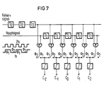
Bei den in der Praxis üblichen hohen Datenraten wird ein möglichst einfacher Korrelator verwendet. Es wird nur das Vorzeichen des Hauptsignals (1 Bit) und das Vorzeichen des Fehlersignals (1 Bit) verwendet, so daß sich der Multiplizierer zu einem EX-OR-GATE (Exclusiv-ODER-Gatter, Mod 2 Multiplikation) vereinfacht. Ein solcher Korrelator mit einem EX-OR-GATE als Multiplizierer ist in Figur 7 dargestellt, wobei auch hier der Einfachheit halber lediglich ein Viertel der Gesamtanordnung wiedergegeben ist wie bei der entsprechenden Korrelatoranordnung in Figur 3. In ihrem übrigen Aufbau stimmen beide Korrelatoren überein, so daß eine nähere Beschreibung der Anordnung nach Figur 7 nicht erforderlich ist.With the high data rates that are common in practice, the simplest possible correlator is used. Only the sign of the main signal (1 bit) and the sign of the error signal (1 bit) are used, so that the multiplier becomes an EX-OR-GATE (exclusive OR gate,
Die Bestimmung des Fehlersignals kann dabei in der Weise erfolgen, wie dies in Figur 5 am Beispiel eines 16 QAM-Signals wiedergegeben ist. Es werden zwei Schwellen zur Ermittlung des Fehlersignals gebildet, die auf den beiden höchststufigen Signalwerten, d.h. der größten bzw. äußersten positiven und negativen Amplitudenstufe liegen. Dabei gilt folgendes: ist das abgetastete Signal größer als die obere Schwelle, dann ist der Fehlerbeitrag positiv; ist der Abtastwert kleiner als die negativste Stufe, dann ist der Fehlerbeitrag negativ. Liegt der Abtastwert jedoch dazwischen, dann ist der Fehlerbeitrag Null, was zu keiner Korrelationsinformation führt. Diese Auswertung der Abtastwerte hat den Vorteil gegenüber einer einzigen Schwelle in der Mitte, daß bei synchronen Datenströmen die eine Abtastung des Fehlerbits, die mit ihrem Augenmittelpunkt des gestörten Nutzsignals zusammenfällt, bei kleinen Störungen auch eine Korrelationsinformation liefert.The error signal can be determined in the manner shown in FIG. 5 using the example of a 16 QAM signal. Two thresholds are formed for determining the error signal, which are based on the two highest-level signal values, i.e. the largest or outermost positive and negative amplitude level. The following applies: if the sampled signal is greater than the upper threshold, then the error contribution is positive; if the sample is smaller than the most negative level, the error contribution is negative. However, if the sample lies in between, the error contribution is zero, which leads to no correlation information. This evaluation of the sampled values has the advantage over a single threshold in the middle that, in the case of synchronous data streams, the one scan of the error bit, which coincides with the center of the eye of the disturbed useful signal, also provides correlation information for small disturbances.
Für die Korrelation ist jetzt noch das Hauptsignal wichtig, das die Depolarisationsstörungen verursacht. Dieses Signal liegt bereits vor, allerdings ist es bezüglich der Fehlerabtastwerte mit einem anderen Träger demoduliert worden. Für die Korrelation wird daher das die Depolarisationsstörung verursachende Signal mit dem komplexen Differenzdrehzeiger der Trägerfrequenzen der beiden Polarisationen multipliziert. Danach kann das für die Korrelation benötigte Hauptsignal durch Abtastung gewonnen werden. Eine Schaltung, die die Ableitung des Fehlersignals und die genannte Multiplikation des Hauptsignals durchführt, also die Eingangssignale zur Korrelatorsteuerung erzeugt, ist für eine Seite des Cancellers in Figur 6 dargestellt. Mit dieser Schaltung werden Störungen des H-Kanals im V-Kanal beseitigt. Dafür werden aus dem I- und Q-Kanal des vertikal polarisierten Signals Signalteile ausgekoppelt und über jeweils einen A/D-Wandler 69,70 auf Fehlersignal-Auswertungen 71,72 gegeben, deren Ausgänge mit jeweils zwei Korrelatoren 73, 75 bzw. 74, 76 der in Figur 4 und 7 beschriebenen Art verbunden sind. Ferner werden Signalteile des I- und Q-Kanals des horizontal polarisierten Signals auf einen Multiplizierer 77 gegeben und in diesem mit dem Differenzdrehzeiger der Trägerfrequenzen fVCOH und fVCOV der nicht synchronen Träger der beiden Polarisation multipliziert. Die Ausgangssignale HIʹ und HQʹ des Multiplizierers 77 gelangen über A/D-Wandler 78,79 an den jeweils zweiten Eingang der Korrelatoren 73,74 bzw. 75, 76. Diese Korrelatoren liefern die Einstellgrößen für die Stellglieder a,b,c und d im Transversalfilter gemäß Figur 2. Dies ist durch die Bezeichnung "control" an den entsprechenden Pfeilen in den Figuren 2 und 6 kenntlich gemacht. Die Multiplikation kann natürlich auch nach den A/D-Wandlern erfolgen.The main signal that causes the depolarization disturbances is now important for the correlation. This signal is already available, but it has been demodulated with another carrier with regard to the error samples. The signal causing the depolarization disturbance with the complex differential pointer is therefore used for the correlation multiplied the carrier frequencies of the two polarizations. The main signal required for the correlation can then be obtained by sampling. A circuit which carries out the derivation of the error signal and the aforementioned multiplication of the main signal, that is to say generates the input signals for correlator control, is shown for one side of the canceller in FIG. 6. This circuit eliminates interference in the H channel in the V channel. For this purpose, signal parts are decoupled from the I and Q channels of the vertically polarized signal, and are passed via an A /
Figur 8 zeigt, wie vorstehend bereits ausgeführt, Diagramme des Störsignals, des Kompensationssignals und der übriggebliebenen Reststörung für ein einfaches Basisbandmodell mit selektiver Depolarisationsstörung für einen Canceller, bestehend aus einem 7Tap-Baudspaced-Transversalfilter. In Gegenüberstellung hierzu sind darunterliegend in Figur 9 entsprechende Diagramme dargestellt für die erfindungsgemäße Anordnung mit einem Canceller, dessen Transversalfilter eine Laufzeit zwischen den Abgriffen von beispielsweise einer halben Symbolperiode (T/2) aufweisen. Damit läßt sich das Abtasttheorem erfüllen und, wie aus Figur 9 ersichtlich, ist die Übereinstimmung von Störsignal und Kompensationssignal zu allen Zeitpunkten wesentlich besser als bei den entsprechenden Diagrammen nach Figur 8. Die übriggebliebene Reststörung ist mit diesem Canceller, der ebenfalls nach dem Zero-Forcing-Algorithmus eingestellt ist, deutlich besser.FIG. 8 shows, as already explained above, diagrams of the interference signal, the compensation signal and the remaining interference for a simple baseband model with selective depolarization interference for a canceller, consisting of a 7-tap baud-spaced transversal filter. In contrast to this, corresponding diagrams are shown below in FIG. 9 for the arrangement according to the invention with a canceller, whose transversal filter has a running time between the taps of for example, have half a symbol period (T / 2). The sampling theorem can thus be fulfilled and, as can be seen from FIG. 9, the interference signal and the compensation signal match at all points in time much better than in the corresponding diagrams according to FIG. 8. The remaining interference is with this canceller, which is also after zero-forcing Algorithm is set significantly better.
Claims (5)
- Adaptive depolarisation interference compensator for digital radio relay systems using multilevel quadrature amplitude modulation (QAM) with same-channel operation of the orthogonally polarised signals, which are not necessarily synchronous with the clock frequency and/or carrier frequency, making use of transversal filters with devices for coupling out signals from the receiving arm of one polarisation and coupling in signals into the receiving path of the other polarisation in each case, comprising a quadrature demodulator, arranged in the receiving arm of the two receivers, which use the same local oscillator or separate local oscillators that are synchronised with respect to one another, for the differently polarised signals, for its two signal components (I and Q channel), and furthermore a canceller, which consists of two complex transversal filters for the two polarisation directions, to which an IF received signal of one polarisation is supplied at the input in each case, and which are coupled at the output into the receiving arm, of the respective other polarisation, characterised in that a quadrature demodulator to which the IF carrier of the respective other polarisation is supplied is connected upstream of the complex transversal filters in each case, in that the delay time between the taps of the transversal filter corresponds at most to half the reciprocal value of the frequency of the highest spectral component of the baseband signal fg (fulfilment of the sampling theorem) preferably with such a rational ratio m/n which supplies a delay time shorter than or equal to

- Compensator according to Claim 1, characterised in that the main signal and the error signal are supplied via delay elements (44...51), which correspond in their delay time to those in the transversal filter, in a time-shifted fashion to a chain of correlators consisting of multipliers (52...57) and integrators (58...62), there being provided in the signal path of the multiplication result a switch-over device (63...68), which switches the multiplication results, which differ during the time n · symbol period of the interference signal (=m · period of the sample clock of the error signal), to the corresponding integrators whose output signals supply the coefficient setting.
- Compensator according to Claim 1 or 2, characterised in that the complex multiplication for deriving the main signal is performed preceding A/D converters (72, 73) arranged in the signal path or thereafter in an appropriately analog or digital manner.
- Compensator according to one of Claims 1 to 3, characterised in that amplitude-quantised sample values are used for the main signal and error signal, preferably a 1-bit quantisation, whose multipliers that are required in the correlators are implemented by an EXOR (exclusive-OR gate, mod 2 multiplication).
- Compensator according to Claim 4, characterised in that in order to obtain the error signal use is made of two thresholds which correspond to the largest or most extreme amplitude levels (positive and negative) of the baseband signal, an error signal sample value above the positive threshold making a positive contribution to the correlation, an error signal sample value below the negative threshold making a negative contribution to the correlation, and an error signal sample value within the two thresholds making no contribution to the correlation.
Priority Applications (1)
| Application Number | Priority Date | Filing Date | Title |
|---|---|---|---|
| AT87106326T ATE64802T1 (en) | 1986-05-06 | 1987-04-30 | ADAPTIVE DEPOLARISATION INTERFERENCE COMPENSATOR. |
Applications Claiming Priority (2)
| Application Number | Priority Date | Filing Date | Title |
|---|---|---|---|
| DE3615314 | 1986-05-06 | ||
| DE3615314 | 1986-05-06 |
Publications (2)
| Publication Number | Publication Date |
|---|---|
| EP0244779A1 EP0244779A1 (en) | 1987-11-11 |
| EP0244779B1 true EP0244779B1 (en) | 1991-06-26 |
Family
ID=6300286
Family Applications (1)
| Application Number | Title | Priority Date | Filing Date |
|---|---|---|---|
| EP87106326A Expired - Lifetime EP0244779B1 (en) | 1986-05-06 | 1987-04-30 | Adaptive depolarization interference compensator |
Country Status (7)
| Country | Link |
|---|---|
| US (1) | US4757319A (en) |
| EP (1) | EP0244779B1 (en) |
| AT (1) | ATE64802T1 (en) |
| AU (1) | AU587123B2 (en) |
| BR (1) | BR8702277A (en) |
| DE (1) | DE3770989D1 (en) |
| ES (1) | ES2022829B3 (en) |
Families Citing this family (23)
| Publication number | Priority date | Publication date | Assignee | Title |
|---|---|---|---|---|
| FR2609224B1 (en) * | 1986-12-30 | 1989-04-07 | Thomson Csf | DEVICE AND METHOD FOR TRANSMITTING AND / OR ACQUIRING DATA USING TWO CROSS POLARIZATIONS OF AN ELECTROMAGNETIC WAVE AND MAGNETIC RECORDING DEVICE |
| FR2615291B1 (en) * | 1987-05-15 | 1989-07-13 | Thomson Csf | METHOD FOR TESTING OPERATION OF A RADAR INFORMATION DISPLAY DEVICE AND IMPLEMENTATION OF THIS METHOD |
| JPS6477235A (en) * | 1987-09-18 | 1989-03-23 | Fujitsu Ltd | Compensating device for interference between cross-polarized waves |
| CA1310709C (en) * | 1989-06-26 | 1992-11-24 | Simon Haykin | Adaptive interference canceller |
| CA2022050C (en) * | 1989-07-27 | 1993-03-23 | Toru Matsuura | Cross-polarization interference cancellation system capable of stably carrying out operation |
| US5068668A (en) * | 1989-09-06 | 1991-11-26 | Hughes Aircraft Company | Adaptive polarization combining system |
| EP0418781B1 (en) * | 1989-09-18 | 1995-12-13 | Nec Corporation | Dual polarization transmission system |
| JP2536207B2 (en) * | 1990-01-23 | 1996-09-18 | 日本電気株式会社 | Interference compensator |
| DE4032067A1 (en) * | 1990-10-10 | 1992-04-16 | Standard Elektrik Lorenz Ag | MANAGEMENT DEVICE FOR COMPENSATING Crosstalk |
| IT1258807B (en) * | 1992-01-22 | 1996-02-29 | Alcatel Italia | METHOD AND SYSTEM FOR THE SYNCHRONIZATION OF MUTUALLY INTERFERING SIGNALS IN NUMERICAL RADIO TRANSMISSIONS WITH FREQUENCY REUSE |
| US5315620A (en) * | 1992-05-01 | 1994-05-24 | Grumman Aerospace Corporation | Arrangement for correction of synchronous demodulator quadrature phase errors |
| US5533063A (en) * | 1994-01-31 | 1996-07-02 | The Regents Of The University Of California | Method and apparatus for multipath channel shaping |
| US5701591A (en) * | 1995-04-07 | 1997-12-23 | Telecommunications Equipment Corporation | Multi-function interactive communications system with circularly/elliptically polarized signal transmission and reception |
| EP0777341B1 (en) * | 1995-11-30 | 2002-02-13 | Loral Aerospace Corporation | Adaptive cross-polarization equalizer |
| US6122334A (en) * | 1997-06-10 | 2000-09-19 | Hughes; Robbin D. | Pilot signal detection filter for a wireless communication device |
| US6233435B1 (en) * | 1997-10-14 | 2001-05-15 | Telecommunications Equipment Corporation | Multi-function interactive communications system with circularly/elliptically polarized signal transmission and reception |
| US6404810B1 (en) * | 1999-04-12 | 2002-06-11 | Level One Communications, Inc. | Activation method in data transceivers |
| DE19926658A1 (en) * | 1999-06-11 | 2000-12-14 | Bosch Gmbh Robert | Receiver for two orthogonally polarized signals |
| US6977973B1 (en) | 2001-10-05 | 2005-12-20 | Raytheon Company | System and method for decoding manchester data |
| ITMI20020371A1 (en) | 2002-02-26 | 2003-08-26 | Cit Alcatel | SYNCHRONIZATION AND CANCELLATION OF TWO OR MORE INTERFERING SIGNALS IN RADIO TRANSMISSIONS WITH FREQUENCY REUSE |
| JP5061400B2 (en) * | 2008-01-09 | 2012-10-31 | 富士フイルム株式会社 | Optical device |
| US8707138B2 (en) * | 2009-05-28 | 2014-04-22 | Xieon Networks S.A.R.L. | Method and arrangement for blind demultiplexing a polarisation diversity multiplex signal |
| US8154451B2 (en) * | 2009-09-13 | 2012-04-10 | Robert Mitchell Zimmerman | Adaptive use of polarization as a means of increased wireless channel capacity |
Family Cites Families (16)
| Publication number | Priority date | Publication date | Assignee | Title |
|---|---|---|---|---|
| US3155965A (en) * | 1961-04-28 | 1964-11-03 | Raytheon Co | Feed-through nulling system |
| US3735266A (en) * | 1971-12-20 | 1973-05-22 | Bell Telephone Labor Inc | Method and apparatus for reducing crosstalk on cross-polarized communication links |
| JPS51115717A (en) * | 1975-03-03 | 1976-10-12 | Nec Corp | Cross polarized wave compensating method |
| US4053882A (en) * | 1976-02-23 | 1977-10-11 | The United States Of America As Represented By The Secretary Of The Air Force | Polarization radar method and system |
| JPS5953738B2 (en) * | 1979-06-05 | 1984-12-26 | ケイディディ株式会社 | Crossed polarization compensation method |
| US4293945A (en) * | 1979-08-29 | 1981-10-06 | Communications Satellite Corporation | Multichannel correlation receiver for determining depolarization of signals along signal propagation paths |
| US4283795A (en) * | 1979-10-03 | 1981-08-11 | Bell Telephone Laboratories, Incorporated | Adaptive cross-polarization interference cancellation arrangements |
| US4466132A (en) * | 1981-04-15 | 1984-08-14 | Nippon Electric Co., Ltd. | Cross-polarization crosstalk elimination circuit |
| US4479258A (en) * | 1981-09-30 | 1984-10-23 | Nippon Electric Co., Ltd. | Cross-polarization crosstalk canceller |
| US4438530A (en) * | 1982-06-14 | 1984-03-20 | Bell Telephone Laboratories, Incorporated | Adaptive cross-polarization interference cancellation system |
| US4561067A (en) * | 1982-06-23 | 1985-12-24 | British Telecommunications | Multi-channel cross-talk interference reduction circuit using modulation-multiplying-demodulation correlator |
| DE3390057T1 (en) * | 1982-06-24 | 1984-07-12 | Rca Corp., Princeton, N.J. | Method and arrangement for correcting cross-polarization errors |
| CA1215430A (en) * | 1982-12-20 | 1986-12-16 | Toshihiko Ryu | Cross-polarization distortion canceller for use in digital radio communication receiver |
| US4577330A (en) * | 1984-04-19 | 1986-03-18 | At&T Bell Laboratories | Cross-polarization interference cancellation arrangement for digital radio channels |
| US4606054A (en) * | 1985-02-21 | 1986-08-12 | At&T Bell Laboratories | Cross-polarization interference cancellation |
| US4631734A (en) * | 1985-03-21 | 1986-12-23 | At&T Bell Laboratories | Cross-polarization canceler/equalizer |
-
1987
- 1987-04-30 ES ES87106326T patent/ES2022829B3/en not_active Expired - Lifetime
- 1987-04-30 EP EP87106326A patent/EP0244779B1/en not_active Expired - Lifetime
- 1987-04-30 DE DE8787106326T patent/DE3770989D1/en not_active Expired - Lifetime
- 1987-04-30 AT AT87106326T patent/ATE64802T1/en not_active IP Right Cessation
- 1987-05-04 US US07/045,476 patent/US4757319A/en not_active Expired - Lifetime
- 1987-05-05 BR BR8702277A patent/BR8702277A/en not_active IP Right Cessation
- 1987-05-05 AU AU72494/87A patent/AU587123B2/en not_active Ceased
Also Published As
| Publication number | Publication date |
|---|---|
| ES2022829B3 (en) | 1991-12-16 |
| ATE64802T1 (en) | 1991-07-15 |
| AU7249487A (en) | 1987-11-12 |
| AU587123B2 (en) | 1989-08-03 |
| EP0244779A1 (en) | 1987-11-11 |
| DE3770989D1 (en) | 1991-08-01 |
| US4757319A (en) | 1988-07-12 |
| BR8702277A (en) | 1988-02-17 |
Similar Documents
| Publication | Publication Date | Title |
|---|---|---|
| EP0244779B1 (en) | Adaptive depolarization interference compensator | |
| DE3604849C2 (en) | Device and method for canceling cross polarization disturbances | |
| DE2727242C3 (en) | Circuit arrangement for simultaneous two-way data transmission via two-wire connections | |
| DE2740123C2 (en) | Echo cancellation arrangement for a digital data transmission system | |
| DE2735945C2 (en) | Circuit arrangement for the carrier synchronization of coherent phase demodulators | |
| DE2214398C3 (en) | Method and arrangement for quickly obtaining the initial convergence of the gain settings in a transversal equalizer | |
| DE69533170T2 (en) | MESSAGE TRANSMISSION SYSTEM WITH ORTHOGONAL CODEMULTIPLEX AND MULTI-CARRYING MODULATION | |
| DE2309167C2 (en) | Method and circuit arrangement for correcting an electrical transmission signal corrupted by phase tremors | |
| EP0208982B1 (en) | Digital branch filter for a data receiver | |
| EP1540858B1 (en) | Method for the transmission of polarisation multiplexed optical signals | |
| DE3713367A1 (en) | CHANNEL ASSESSMENT AND DETECTION IN DIGITAL COMMUNICATION SYSTEMS | |
| DE3737006A1 (en) | CANCELLATION ARRANGEMENT FOR CROSS-POLARIZATION MALFUNCTIONS IN A ROOM DIVERSITY RADIO SYSTEM | |
| DE2503595A1 (en) | DATA RECEIVER FOR SYNCHRONOUS SQUARE AMPLITUDE MODULATED DATA SIGNALS | |
| DE3223408A1 (en) | COMMUNITY ANTENNA ARRANGEMENT FOR RECEIVING AND DISTRIBUTING TELEVISION AND DIGITAL AUDIO SIGNALS | |
| DE3590158T1 (en) | Method for obtaining time and frequency synchronization in modems that uses known symbols (as non-data) as part of their normally transmitted data format | |
| DE4229573A1 (en) | RADIO RECEIVER AND TRANSMITTER WITH DIVERSITY | |
| DE3005196A1 (en) | RECEIVING DEVICE FOR DIGITAL SIGNALS | |
| DE1762010B2 (en) | Method and circuit for the transmission of digital data via a transmission link composed in particular of telephone lines | |
| DE2216350A1 (en) | Numerical filter and digital data transmission system with this filter | |
| DE2317597B2 (en) | Method and circuit arrangement for equalizing a signal afflicted with linear distortions after transmission by means of phase modulation before demodulation | |
| DE4405817C2 (en) | Automatic equalizer | |
| EP0179393B1 (en) | Intermediate frequency transversal equalizer | |
| DE2141484A1 (en) | Transmission system and this includes the transmitter and receiver for transmitting synchronous pulse signals | |
| DE2653970C2 (en) | Message transmission method | |
| DE3730399A1 (en) | Method and device for transmitting a digital signal |
Legal Events
| Date | Code | Title | Description |
|---|---|---|---|
| PUAI | Public reference made under article 153(3) epc to a published international application that has entered the european phase |
Free format text: ORIGINAL CODE: 0009012 |
|
| AK | Designated contracting states |
Kind code of ref document: A1 Designated state(s): AT BE CH DE ES FR GB GR IT LI NL SE |
|
| 17P | Request for examination filed |
Effective date: 19880309 |
|
| 17Q | First examination report despatched |
Effective date: 19900322 |
|
| GRAA | (expected) grant |
Free format text: ORIGINAL CODE: 0009210 |
|
| AK | Designated contracting states |
Kind code of ref document: B1 Designated state(s): AT CH DE ES GB IT LI NL |
|
| REF | Corresponds to: |
Ref document number: 64802 Country of ref document: AT Date of ref document: 19910715 Kind code of ref document: T |
|
| REF | Corresponds to: |
Ref document number: 3770989 Country of ref document: DE Date of ref document: 19910801 |
|
| ITF | It: translation for a ep patent filed |
Owner name: STUDIO JAUMANN |
|
| GBT | Gb: translation of ep patent filed (gb section 77(6)(a)/1977) | ||
| EN | Fr: translation not filed | ||
| PLBE | No opposition filed within time limit |
Free format text: ORIGINAL CODE: 0009261 |
|
| STAA | Information on the status of an ep patent application or granted ep patent |
Free format text: STATUS: NO OPPOSITION FILED WITHIN TIME LIMIT |
|
| 26N | No opposition filed | ||
| PGFP | Annual fee paid to national office [announced via postgrant information from national office to epo] |
Ref country code: ES Payment date: 19950405 Year of fee payment: 9 |
|
| PGFP | Annual fee paid to national office [announced via postgrant information from national office to epo] |
Ref country code: AT Payment date: 19960327 Year of fee payment: 10 |
|
| PG25 | Lapsed in a contracting state [announced via postgrant information from national office to epo] |
Ref country code: ES Free format text: LAPSE BECAUSE OF NON-PAYMENT OF DUE FEES Effective date: 19960503 |
|
| PGFP | Annual fee paid to national office [announced via postgrant information from national office to epo] |
Ref country code: GB Payment date: 19970321 Year of fee payment: 11 |
|
| PGFP | Annual fee paid to national office [announced via postgrant information from national office to epo] |
Ref country code: NL Payment date: 19970428 Year of fee payment: 11 |
|
| PG25 | Lapsed in a contracting state [announced via postgrant information from national office to epo] |
Ref country code: AT Effective date: 19970430 |
|
| PGFP | Annual fee paid to national office [announced via postgrant information from national office to epo] |
Ref country code: CH Payment date: 19970715 Year of fee payment: 11 |
|
| PG25 | Lapsed in a contracting state [announced via postgrant information from national office to epo] |
Ref country code: LI Free format text: LAPSE BECAUSE OF NON-PAYMENT OF DUE FEES Effective date: 19980430 Ref country code: GB Free format text: LAPSE BECAUSE OF NON-PAYMENT OF DUE FEES Effective date: 19980430 Ref country code: CH Free format text: LAPSE BECAUSE OF NON-PAYMENT OF DUE FEES Effective date: 19980430 |
|
| PG25 | Lapsed in a contracting state [announced via postgrant information from national office to epo] |
Ref country code: NL Free format text: LAPSE BECAUSE OF NON-PAYMENT OF DUE FEES Effective date: 19981101 |
|
| REG | Reference to a national code |
Ref country code: CH Ref legal event code: PL |
|
| GBPC | Gb: european patent ceased through non-payment of renewal fee |
Effective date: 19980430 |
|
| NLV4 | Nl: lapsed or anulled due to non-payment of the annual fee |
Effective date: 19981101 |
|
| REG | Reference to a national code |
Ref country code: ES Ref legal event code: FD2A Effective date: 19990301 |
|
| PGFP | Annual fee paid to national office [announced via postgrant information from national office to epo] |
Ref country code: IT Payment date: 20060430 Year of fee payment: 20 |
|
| PGFP | Annual fee paid to national office [announced via postgrant information from national office to epo] |
Ref country code: DE Payment date: 20060619 Year of fee payment: 20 |