EP0244592B1 - Sicherheitseinrichtung, verwendbar für die Aktivierung von Streuminen - Google Patents
Sicherheitseinrichtung, verwendbar für die Aktivierung von Streuminen Download PDFInfo
- Publication number
- EP0244592B1 EP0244592B1 EP87103254A EP87103254A EP0244592B1 EP 0244592 B1 EP0244592 B1 EP 0244592B1 EP 87103254 A EP87103254 A EP 87103254A EP 87103254 A EP87103254 A EP 87103254A EP 0244592 B1 EP0244592 B1 EP 0244592B1
- Authority
- EP
- European Patent Office
- Prior art keywords
- fact
- cover
- mine
- pin
- bottom wall
- Prior art date
- Legal status (The legal status is an assumption and is not a legal conclusion. Google has not performed a legal analysis and makes no representation as to the accuracy of the status listed.)
- Expired - Lifetime
Links
Images


Classifications
-
- F—MECHANICAL ENGINEERING; LIGHTING; HEATING; WEAPONS; BLASTING
- F42—AMMUNITION; BLASTING
- F42B—EXPLOSIVE CHARGES, e.g. FOR BLASTING, FIREWORKS, AMMUNITION
- F42B23/00—Land mines ; Land torpedoes
- F42B23/24—Details
-
- F—MECHANICAL ENGINEERING; LIGHTING; HEATING; WEAPONS; BLASTING
- F42—AMMUNITION; BLASTING
- F42B—EXPLOSIVE CHARGES, e.g. FOR BLASTING, FIREWORKS, AMMUNITION
- F42B12/00—Projectiles, missiles or mines characterised by the warhead, the intended effect, or the material
- F42B12/02—Projectiles, missiles or mines characterised by the warhead, the intended effect, or the material characterised by the warhead or the intended effect
- F42B12/36—Projectiles, missiles or mines characterised by the warhead, the intended effect, or the material characterised by the warhead or the intended effect for dispensing materials; for producing chemical or physical reaction; for signalling ; for transmitting information
- F42B12/56—Projectiles, missiles or mines characterised by the warhead, the intended effect, or the material characterised by the warhead or the intended effect for dispensing materials; for producing chemical or physical reaction; for signalling ; for transmitting information for dispensing discrete solid bodies
- F42B12/58—Cluster or cargo ammunition, i.e. projectiles containing one or more submissiles
- F42B12/62—Cluster or cargo ammunition, i.e. projectiles containing one or more submissiles the submissiles being ejected parallel to the longitudinal axis of the projectile
Definitions
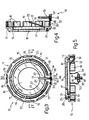
- a mine essentially of known type is indicated generally with the reference numeral 1, which from the structural point of view has a body 2 constituted by two frusto-conical portions 3, 4 respectively joined at their larger bases the diameters of which are identical.
- a dome 6 extends axially and in a central position from the portion 4, which dome acts as a sensor element of the mine 1 which, if pressed, controls the explosion of the mine itself.
- This latter further has, within its portion 4, a radial socket through which it is possible to intercept and lock the arming mechanism (not illustrated) of the mine itself.
- This spring 12 has, finally, in a median zone of its portion 21, a deformed portion 27 in the form of a hump able to establish an interference in a transverse sense with the opposite walls of the groove 20 (see Figure 3) in such a way as to obtain a precise and constant positioning of the spring 12 with respect to this groove and therefore with respect to the cover 11.
- the launching tube 50 has a side wall 51 which is closed at one end by means of a plug 52 and at the other end by an expulsion device 53 of known type.
- the plug 52 is fixed internally to the wall 51 of the tube 5 by means of a plurality of gripper teeth 54 which engage an annular groove 55 formed on the inside of the said wall 51.
- the cover 52 has an annular seat 56 which receives an annular seal 57 interposed between the plug 52 and the facing inner surface of the wall 51.
Landscapes
- Engineering & Computer Science (AREA)
- General Engineering & Computer Science (AREA)
- Chemical & Material Sciences (AREA)
- Combustion & Propulsion (AREA)
- Snaps, Bayonet Connections, Set Pins, And Snap Rings (AREA)
- Pretreatment Of Seeds And Plants (AREA)
- Disintegrating Or Milling (AREA)
- Respiratory Apparatuses And Protective Means (AREA)
- Arc Welding In General (AREA)
- Carbon And Carbon Compounds (AREA)
- Solid-Sorbent Or Filter-Aiding Compositions (AREA)
- Earth Drilling (AREA)
Claims (14)
Priority Applications (1)
| Application Number | Priority Date | Filing Date | Title |
|---|---|---|---|
| AT87103254T ATE57434T1 (de) | 1986-03-25 | 1987-03-06 | Sicherheitseinrichtung, verwendbar fuer die aktivierung von streuminen. |
Applications Claiming Priority (2)
| Application Number | Priority Date | Filing Date | Title |
|---|---|---|---|
| IT5318386U | 1986-03-25 | ||
| IT8653183U IT207899Z2 (it) | 1986-03-25 | 1986-03-25 | Dispositivo di sicurezza utilizzabile per l attivazione di mine semina bili |
Publications (2)
| Publication Number | Publication Date |
|---|---|
| EP0244592A1 EP0244592A1 (de) | 1987-11-11 |
| EP0244592B1 true EP0244592B1 (de) | 1990-10-10 |
Family
ID=11280639
Family Applications (1)
| Application Number | Title | Priority Date | Filing Date |
|---|---|---|---|
| EP87103254A Expired - Lifetime EP0244592B1 (de) | 1986-03-25 | 1987-03-06 | Sicherheitseinrichtung, verwendbar für die Aktivierung von Streuminen |
Country Status (6)
| Country | Link |
|---|---|
| EP (1) | EP0244592B1 (de) |
| AT (1) | ATE57434T1 (de) |
| DE (1) | DE3765453D1 (de) |
| ES (1) | ES2017946B3 (de) |
| GR (1) | GR3001166T3 (de) |
| IT (1) | IT207899Z2 (de) |
Cited By (1)
| Publication number | Priority date | Publication date | Assignee | Title |
|---|---|---|---|---|
| PL444564A1 (pl) * | 2023-04-24 | 2024-10-28 | Wojskowy Instytut Techniki Inżynieryjnej Im. Profesora Józefa Kosackiego | Mechanizm do usuwania zawleczek zabezpieczeń transportowych |
Family Cites Families (3)
| Publication number | Priority date | Publication date | Assignee | Title |
|---|---|---|---|---|
| DE2428340C3 (de) * | 1974-06-12 | 1978-10-05 | Fa. Diehl, 8500 Nuernberg | Übersprengsicherer Zug- und Druckzünder |
| IE44663B1 (en) * | 1976-04-23 | 1982-02-10 | Redon Trust | Non-magnetic anti-personell war-mine |
| FR2547911B1 (fr) * | 1983-06-27 | 1985-12-13 | Lacroix E Tous Artifices | Mine antichar dispersable a positionnement automatique |
-
1986
- 1986-03-25 IT IT8653183U patent/IT207899Z2/it active
-
1987
- 1987-03-06 AT AT87103254T patent/ATE57434T1/de not_active IP Right Cessation
- 1987-03-06 EP EP87103254A patent/EP0244592B1/de not_active Expired - Lifetime
- 1987-03-06 ES ES87103254T patent/ES2017946B3/es not_active Expired - Lifetime
- 1987-03-06 DE DE8787103254T patent/DE3765453D1/de not_active Expired - Fee Related
-
1990
- 1990-12-05 GR GR90401036T patent/GR3001166T3/el unknown
Cited By (1)
| Publication number | Priority date | Publication date | Assignee | Title |
|---|---|---|---|---|
| PL444564A1 (pl) * | 2023-04-24 | 2024-10-28 | Wojskowy Instytut Techniki Inżynieryjnej Im. Profesora Józefa Kosackiego | Mechanizm do usuwania zawleczek zabezpieczeń transportowych |
Also Published As
| Publication number | Publication date |
|---|---|
| EP0244592A1 (de) | 1987-11-11 |
| ATE57434T1 (de) | 1990-10-15 |
| ES2017946B3 (es) | 1991-03-16 |
| GR3001166T3 (en) | 1992-06-30 |
| IT8653183V0 (it) | 1986-03-25 |
| IT207899Z2 (it) | 1988-02-22 |
| DE3765453D1 (de) | 1990-11-15 |
Similar Documents
| Publication | Publication Date | Title |
|---|---|---|
| US4132147A (en) | Store retention and release mechanism | |
| US4289073A (en) | Warhead with a plurality of slave missiles | |
| US4850280A (en) | Propelling cage projectile arrangement | |
| CA2114735A1 (en) | Missile | |
| JPS6347756Y2 (de) | ||
| US4044684A (en) | Aerosol projectile for lachrymating material | |
| US4134328A (en) | Device for a missile | |
| EP0244592B1 (de) | Sicherheitseinrichtung, verwendbar für die Aktivierung von Streuminen | |
| US5549047A (en) | Submunition fuse with a nondelay self-destruct firing device | |
| US4628821A (en) | Acceleration actuated kinetic energy penetrator retainer | |
| EP1185836B1 (de) | Verriegelungs- und verschiebevorrichtung in einer rakete | |
| US4697765A (en) | Parachute reefing/release device | |
| US5684267A (en) | Resupply projectile | |
| US3985079A (en) | Self-destruct fuze for spinning artillery projectile | |
| US4028886A (en) | Passive chamber wall fragmenter | |
| US5345874A (en) | Automatic ejection system for trip-wire type mines | |
| US3534613A (en) | Sampling apparatus | |
| GB2024920A (en) | Ejectable coupling | |
| US4667600A (en) | Safe/arm explosive transfer mechanism | |
| US3678859A (en) | Two stage impact fuze | |
| US4658725A (en) | Fuse for a small bomb | |
| US4632010A (en) | AIRBOC chaff deployment system | |
| US4109577A (en) | Device for bottom unit for projectile | |
| US4063514A (en) | Grenade fuze | |
| US4726297A (en) | Submunition ejection system |
Legal Events
| Date | Code | Title | Description |
|---|---|---|---|
| PUAI | Public reference made under article 153(3) epc to a published international application that has entered the european phase |
Free format text: ORIGINAL CODE: 0009012 |
|
| AK | Designated contracting states |
Kind code of ref document: A1 Designated state(s): AT BE DE ES FR GB GR SE |
|
| 17P | Request for examination filed |
Effective date: 19880421 |
|
| 17Q | First examination report despatched |
Effective date: 19890329 |
|
| GRAA | (expected) grant |
Free format text: ORIGINAL CODE: 0009210 |
|
| AK | Designated contracting states |
Kind code of ref document: B1 Designated state(s): AT BE DE ES FR GB GR SE |
|
| PG25 | Lapsed in a contracting state [announced via postgrant information from national office to epo] |
Ref country code: SE Effective date: 19901010 Ref country code: BE Effective date: 19901010 Ref country code: AT Effective date: 19901010 |
|
| REF | Corresponds to: |
Ref document number: 57434 Country of ref document: AT Date of ref document: 19901015 Kind code of ref document: T |
|
| ET | Fr: translation filed | ||
| REF | Corresponds to: |
Ref document number: 3765453 Country of ref document: DE Date of ref document: 19901115 |
|
| PLBE | No opposition filed within time limit |
Free format text: ORIGINAL CODE: 0009261 |
|
| STAA | Information on the status of an ep patent application or granted ep patent |
Free format text: STATUS: NO OPPOSITION FILED WITHIN TIME LIMIT |
|
| REG | Reference to a national code |
Ref country code: GR Ref legal event code: FG4A Free format text: 3001166 |
|
| 26N | No opposition filed | ||
| PGFP | Annual fee paid to national office [announced via postgrant information from national office to epo] |
Ref country code: GB Payment date: 19930301 Year of fee payment: 7 |
|
| PGFP | Annual fee paid to national office [announced via postgrant information from national office to epo] |
Ref country code: FR Payment date: 19930312 Year of fee payment: 7 |
|
| PGFP | Annual fee paid to national office [announced via postgrant information from national office to epo] |
Ref country code: ES Payment date: 19930316 Year of fee payment: 7 |
|
| PGFP | Annual fee paid to national office [announced via postgrant information from national office to epo] |
Ref country code: GR Payment date: 19930331 Year of fee payment: 7 |
|
| PGFP | Annual fee paid to national office [announced via postgrant information from national office to epo] |
Ref country code: DE Payment date: 19930422 Year of fee payment: 7 |
|
| PG25 | Lapsed in a contracting state [announced via postgrant information from national office to epo] |
Ref country code: GB Effective date: 19940306 |
|
| PG25 | Lapsed in a contracting state [announced via postgrant information from national office to epo] |
Ref country code: ES Free format text: LAPSE BECAUSE OF THE APPLICANT RENOUNCES Effective date: 19940307 |
|
| PG25 | Lapsed in a contracting state [announced via postgrant information from national office to epo] |
Ref country code: GR Free format text: THE PATENT HAS BEEN ANNULLED BY A DECISION OF A NATIONAL AUTHORITY Effective date: 19940930 |
|
| GBPC | Gb: european patent ceased through non-payment of renewal fee |
Effective date: 19940306 |
|
| PG25 | Lapsed in a contracting state [announced via postgrant information from national office to epo] |
Ref country code: FR Effective date: 19941130 |
|
| PG25 | Lapsed in a contracting state [announced via postgrant information from national office to epo] |
Ref country code: DE Effective date: 19941201 |
|
| REG | Reference to a national code |
Ref country code: FR Ref legal event code: ST |
|
| REG | Reference to a national code |
Ref country code: GR Ref legal event code: MM2A Free format text: 3001166 |
|
| REG | Reference to a national code |
Ref country code: ES Ref legal event code: FD2A Effective date: 19991007 |