EP0244484A1 - Transfer apparatus for plate type materials - Google Patents
Transfer apparatus for plate type materials Download PDFInfo
- Publication number
- EP0244484A1 EP0244484A1 EP85905104A EP85905104A EP0244484A1 EP 0244484 A1 EP0244484 A1 EP 0244484A1 EP 85905104 A EP85905104 A EP 85905104A EP 85905104 A EP85905104 A EP 85905104A EP 0244484 A1 EP0244484 A1 EP 0244484A1
- Authority
- EP
- European Patent Office
- Prior art keywords
- plate type
- conveyor
- type material
- speed
- died
- Prior art date
- Legal status (The legal status is an assumption and is not a legal conclusion. Google has not performed a legal analysis and makes no representation as to the accuracy of the status listed.)
- Withdrawn
Links
Images


Classifications
-
- B—PERFORMING OPERATIONS; TRANSPORTING
- B65—CONVEYING; PACKING; STORING; HANDLING THIN OR FILAMENTARY MATERIAL
- B65H—HANDLING THIN OR FILAMENTARY MATERIAL, e.g. SHEETS, WEBS, CABLES
- B65H5/00—Feeding articles separated from piles; Feeding articles to machines
- B65H5/34—Varying the phase of feed relative to the receiving machine
-
- B—PERFORMING OPERATIONS; TRANSPORTING
- B65—CONVEYING; PACKING; STORING; HANDLING THIN OR FILAMENTARY MATERIAL
- B65H—HANDLING THIN OR FILAMENTARY MATERIAL, e.g. SHEETS, WEBS, CABLES
- B65H43/00—Use of control, checking, or safety devices, e.g. automatic devices comprising an element for sensing a variable
-
- B—PERFORMING OPERATIONS; TRANSPORTING
- B65—CONVEYING; PACKING; STORING; HANDLING THIN OR FILAMENTARY MATERIAL
- B65H—HANDLING THIN OR FILAMENTARY MATERIAL, e.g. SHEETS, WEBS, CABLES
- B65H2701/00—Handled material; Storage means
- B65H2701/10—Handled articles or webs
- B65H2701/17—Nature of material
- B65H2701/176—Cardboard
- B65H2701/1762—Corrugated
Definitions
- the present invention relates to a conveyor system for carrying planar objects by way of a conveyor belt and the like.
- Corrugated cardboard boxes have been designed with a variety of sizes, shapes and in a variety of multicolor printings these days, and in coping with such designs, there have been presented a variety of functions of the machine for manufacturing the corrugated cardboard boxes, accordingly. Now, referring to the conventional construction of the corrugated cardboard box manufacturing machine with reference to FIGS.
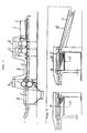
- a blank board supply station 1 a first printing machine 2, a second printing machine 3, printing cylinders 4, a transfer conveyor 5, a rotary die cutting station 6, a anvil cylinder 7, a die-cut cylinder 8, a die element 9, a board delivery conveyor (a scrap conveyor; a conveyor for a planar object) 10, a sheet of corrugated board 11, a died board 11' (through the single-cutting process), a died board 11" (through the double-cutting process), a stacker-conveyor 12, a counter-stacker 13, a board stopper 14, a spacing 16, a lifter 17, and a counting photoelectric tube 18, wherein a sheet of corrugated cardboard 11 is fed for printing by the board supply station 1 with such a rate of delivery of a sheet per single rotation of the printing cylinders 4 in the printing machines 2, 3, thereafter is delivered outwardly by the transfer conveyor 5 for having the printing ink put in the surface of a carboard 11 dried up, and then is died to a shape of cardboard box by way
- the die element 9 comprises a cutting knife edge or the like implanted around the circumferential surface of a curved veneer board of a specified thickness, which is to be mounted onto the die-cut cylinder 8 by using bolts, and is adapted to cut and die a sheet of carboard 11 to be fed from the foregoing step into the nip with the anvil cylinder 7, which is wrapped with a layer of urethane rubber or the like for making the cutting easier and preventing the wear of cutting edge, with a predetermined timing of cuting and dieing.
- the delivery conveyor (scrap conveyor) 10 is formed by a plurality of such carrier members as V-shaped belts or ropes having a circular section in an attempt to promote the dropping of chippings and cuttings from the product at the area where there is provided a specific means such as an air blower or a vibrator, and is constructed in a duplex structure for carrying the died board 11' in a sandwiched relationship over to a stacker-conveyor 12. There is provided a suction equipment in the stacker-conveyor 12.
- the cardboard stopper 14 is designed shiftable back and forth by way of a hydraulic cylinder or the like in accordance with a given width of the died board 11' as schematically shown in FIGS. 1 and 2.
- the cardboard box manufacturing machine is of the type that a sheet of cardboard 11 may be set either for one-piece cutting or for longitudinal double-piece cutting according to the size of a box to be died by using the die element 9 of the rotary die cutter 6.
- FIG. 3(111) shows the case of the single-piece cutting process
- FIG. 4(111) shows the longitudinal double-piece cutting
- FIG. 4(IV) shows the four-piece cutting process (double-cuttings in the transversal and longitudinal ways making four pieces of boards), respectively.
- the die element 9 is to be set in the circumferential surface of the die cut cylinder 8, with a single-piece or double-piece cutting knife element implanted in working position in accordance with the size of a product box to be manufactured, and with a spacing 16.
- This spacing 16 is provided for the reduction of conveying speed in consideration of a too great shock to be given to the died cardboard 11' when hit against the cardboard stopper 14, which is taken in the following manner; when a series of died cardboards 11' after being died by the die cut cylinder 8 are stacked upon the lifter 17 by using the stacker-conveyor 12, as the carrying speed of the stacker-conveyor 12 will, when the single-piece cutting is conducted (FIG.
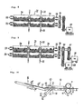
- FIG. 6 Shown in FIG. 6 are an anvil cylinder 7, a die-cut cylinder 8, a die element 9, a sheet delivery conveyor (scrap conveyor) 10, a died sheet (through the double-piece cutting process) 11", a stacker-conveyor 12, a counter-stacker 13, a spacing 16, an photoelectric tube 32, and a sandwiching roll section 31, and shown in FIG. 8 are sandwich (rubber) roll elements 34, 34, a bearing 35, gears 36, and a DC (variable speed) motor 37.
- FIG. 5 is a schematic diagram showing a series of died sheets 1 through 6 before delvered from the sandwich roll elements 34, 34, in which L depicts the circumferential length of the die-cut cylinder 8. Also in FIG.
- FIG. 8 there is shown a timing chart showing the changes of rotating speed of the sandwich roll elements 34, 34.
- the sandwich roll elements 34, 34 shown in FIG. 8 are fixed in operative position on a single roll shaft 33 disposed with a given gap, and are arranged opposedly to respectively form a pair of rolls in the sandwiching roll section 31.
- Each of these sandwich roll elements 34 is formed with a layer of soft rubber sheet in its circumference so that it may not squeeze and crush the corrugated cardboard sheets while passing therethrough, and also may be worked with slitting.
- the upper and lower roll shafts 33 are held rotatably by using the bearings 35 and operatively in such a manner that the cardboard sheet may be carried in a sandwiching manner by the engagement of the sandwich roll elements 34, 34, and on one sides of these roll shafts 33 there are fitted the gears 36 meshing with each other at the ratio of 1:1.
- any change in the rotating speed of the sandwich roll elements 34, 34 may be accomplished by detecting the current edge position of a cardboard sheet to be fed at or near the central portion of the upper and lower sandwich roll elements 34, 34, and by feeding thus-obtained signal into the DC motor 37, and thus changing the rotating speed of the DC motor 37, accordingly.
- the sheets 1, 2; 3, 4; 5, 6 depicts respectively the state of sheets fed from the blank cardboard supply station 1, or in other words the state that these sheets are disposed in a discrete relationship with each other.
- the spaces between the sheets 2 and 3, and between @ and 6 represent a difference in the circumferential length of the die cut cylinder 8 and the overall extension of the died sheets 1 and 2.
- ⁇ l represents a small gap produced between each of the adjacent died sheets.
- the rotating speed (the circumferential speed of the roll surface) V 3 of the sandwich roll element 34 (or the rotating speed of the DC motor 37), which may be known by detecting the timing that the edge of the died cardboard 11' passes by using the photoelectric tube 32, is changed as shown in the timing chart of FIG. 7.
- FIG. 7 shows the relationship between the timing of detecting the passage of the died cardboard 11' by the photoelectric tube 32 (that is, the case that the gap between the adjacent sheets is detected is defined to be the light receiving state, while the case that a sheet is detected being defined to be the light blocking state.) and the current rotating speed of the sandwich roll element 34.
- the driving speed of the upper and lower sandwich roll elements 34, 34 is increased or reduced with the same speed rate in proportion to the rotating speed V 2 of the die cut cylinder 8.
- FIG. 9 shows another embodiment of the invention wherein the rotating speed of the sandwich roll element 34 is changed by shifting a first electromagnetic clutch 40, etc. incorporated or installed otherwise in a motor 38 and a pulley and a second electromagnetic clutch 41, etc. incorporated or installed otherwise in a second motor 39 and a pulley, with which embodiment there is attainable an equivalent effect and function to that of the previous embodiment.
- FIG. 10 shows a further embodiment of the invention, wherein the sandwich roll elements and the speed change device are replaced with a conveyor belt 44, a conveyor roll 45 and a motor 42, with which there is also attainable an equivalent effect and function to that of the embodiment described hereinbefore.
Landscapes
- Engineering & Computer Science (AREA)
- Mechanical Engineering (AREA)
- Separation, Sorting, Adjustment, Or Bending Of Sheets To Be Conveyed (AREA)
- Delivering By Means Of Belts And Rollers (AREA)
Abstract
Description
- The present invention relates to a conveyor system for carrying planar objects by way of a conveyor belt and the like.
- Corrugated cardboard boxes have been designed with a variety of sizes, shapes and in a variety of multicolor printings these days, and in coping with such designs, there have been presented a variety of functions of the machine for manufacturing the corrugated cardboard boxes, accordingly. Now, referring to the conventional construction of the corrugated cardboard box manufacturing machine with reference to FIGS. 1 through 4, there are shown provided a blank
board supply station 1, afirst printing machine 2, asecond printing machine 3,printing cylinders 4, atransfer conveyor 5, a rotarydie cutting station 6, aanvil cylinder 7, a die-cutcylinder 8, adie element 9, a board delivery conveyor (a scrap conveyor; a conveyor for a planar object) 10, a sheet ofcorrugated board 11, a died board 11' (through the single-cutting process), a diedboard 11" (through the double-cutting process), a stacker-conveyor 12, acounter-stacker 13, a board stopper 14, aspacing 16, alifter 17, and a counting photoelectric tube 18, wherein a sheet ofcorrugated cardboard 11 is fed for printing by theboard supply station 1 with such a rate of delivery of a sheet per single rotation of theprinting cylinders 4 in theprinting machines transfer conveyor 5 for having the printing ink put in the surface of acarboard 11 dried up, and then is died to a shape of cardboard box by way of therotary die cutter 6. Thedie element 9 comprises a cutting knife edge or the like implanted around the circumferential surface of a curved veneer board of a specified thickness, which is to be mounted onto the die-cutcylinder 8 by using bolts, and is adapted to cut and die a sheet ofcarboard 11 to be fed from the foregoing step into the nip with theanvil cylinder 7, which is wrapped with a layer of urethane rubber or the like for making the cutting easier and preventing the wear of cutting edge, with a predetermined timing of cuting and dieing. The delivery conveyor (scrap conveyor) 10 is formed by a plurality of such carrier members as V-shaped belts or ropes having a circular section in an attempt to promote the dropping of chippings and cuttings from the product at the area where there is provided a specific means such as an air blower or a vibrator, and is constructed in a duplex structure for carrying the died board 11' in a sandwiched relationship over to a stacker-conveyor 12. There is provided a suction equipment in the stacker-conveyor 12. which is adapted to attract by sucking and deliver the died cardboard 11' at a slow speed in the attempt to reduce a impact shock of the board against thecardboard stopper 14 provided in thecounter-stacker 13 when hit, thus obviating a possibility of damages and/or irregular stacking of the cardboards from occurring when stacked upon thelifter 17. Also, thecardboard stopper 14 is designed shiftable back and forth by way of a hydraulic cylinder or the like in accordance with a given width of the died board 11' as schematically shown in FIGS. 1 and 2. - The cardboard box manufacturing machine is of the type that a sheet of
cardboard 11 may be set either for one-piece cutting or for longitudinal double-piece cutting according to the size of a box to be died by using thedie element 9 of therotary die cutter 6. FIG. 3(111) shows the case of the single-piece cutting process, FIG. 4(111) shows the longitudinal double-piece cutting, and FIG. 4(IV) shows the four-piece cutting process (double-cuttings in the transversal and longitudinal ways making four pieces of boards), respectively. The dieelement 9 is to be set in the circumferential surface of thedie cut cylinder 8, with a single-piece or double-piece cutting knife element implanted in working position in accordance with the size of a product box to be manufactured, and with aspacing 16. Thisspacing 16 is provided for the reduction of conveying speed in consideration of a too great shock to be given to the died cardboard 11' when hit against thecardboard stopper 14, which is taken in the following manner; when a series of died cardboards 11' after being died by the die cutcylinder 8 are stacked upon thelifter 17 by using the stacker-conveyor 12, as the carrying speed of the stacker-conveyor 12 will, when the single-piece cutting is conducted (FIG. 3(111)), bring a too large shock on the died sheet 11' when hit against thecardboard stopper 14, if V1V2 (the circumferential speed of the
die cut cylinder 8 and the carrying speed of thedelivery conveyor 10 are V2, and the carrying speed of the stacker-conveyor 12 is V1 , as shown in FIG. 3(I)), the speed V1 of the stacker-conveyor 12 is then reduced by using thespacing 16 as shown in FIG. 3(II) to:
conveyor 12 is reduced down to V = V2 ×ℓ/L as shownin FIG. 4(II), since thesheet 11" died for the double-cutting process is cut to the shape in which the foregoing piece and the following piece are left connected with each other by the die cutter, it would not be feasible to have normal cutting operation as these diedsheets 11" may come to overlap one upon the other, and consequently, the carrying speed V1 of the stacker-conveyor 12 is forcibly made V1V2 as shown in FIG. 4(1) (identical with FIG. 3(1)), then resulting in such undesirable problems that the leading edges of the diedsheet 11" would be damaged by a too large shock load when hit against thecardboard stopper 14 in stacking, or the diedsheets 11" would be stacked irregularly. - In consideration of the problems noted above, it is an object of the present invention to provide an improved conveyor system for planar objects which can obviate such a possibility of damages to be received while being stacked or an inconvenience of irregular stacking in the step following the die-cutting process.
- In the conveyor system according to the present invention, there are provided a detecting device adapted to detect the current end position of a planar object fed from the preceding step, a delivery member adapted to deliver the planar object while having it sandwiched therebetween, and a speed change device adapted to change the delivery speed of the delivery member in accordance with the timing of the following step on the basis of the signal from the detecting device, and as the conveying speed of the following stacker-conveyor can be made as slow as VI = 2ℓ/L even with the died sheet processed in the double-piece cutting operation, there is attained such advantageous effects as avoiding the risk of damaged rendered at the leading edge of a died sheet or the inconveniences of irregular stacking while being stacked upon the stacker-conveyor in the following step, accordingly.
- In addition, there are required only such simple delivery members as two small-diametered sandwiching rolls to be driven for the delivery of the processed sheets, which would have a relatively small inertia value GDr and therefore require a relatively small capacity driving motor, thus contributing to the curtailment of cost, and which is proven to be adaptable to the double-sheet cutting operation and so useful in the application to the general purpose machine for manufacturing the corrugated cardboard boxes.
- The present invention will now be described taking the reference to preferred embodiments thereof shown in the accompanying drawings.
-
- FIG. 5 is a schematic diagram illustrating the mutual relationship of a series of planar objects aligned on the delivery to the delivery member according to the present invention;
- FIG. 6 is a side elevational view showing a preferred embodiment of the conveyor system for the planar objects according to the present invention;
- FIG. 7 is an illustrative diagram for depicting the function of the conveyor system;
- FIG. 8 is a front elevational view showing the speed change device and parts relative thereto of the conveyor system;
- FIG. 9 is a front elevational view showing the same speed change device and parts relative thereto by way of another embodiment; and
- FIG. 10 is a general side elevational view showing the delivery member construction by way of another embodiment.
- Shown in FIG. 6 are an
anvil cylinder 7, a die-cutcylinder 8, adie element 9, a sheet delivery conveyor (scrap conveyor) 10, a died sheet (through the double-piece cutting process) 11", a stacker-conveyor 12, acounter-stacker 13, aspacing 16, anphotoelectric tube 32, and asandwiching roll section 31, and shown in FIG. 8 are sandwich (rubber)roll elements bearing 35,gears 36, and a DC (variable speed)motor 37. Also, FIG. 5 is a schematic diagram showing a series of diedsheets ① through ⑥ before delvered from thesandwich roll elements cylinder 8. Also in FIG. 7 there is shown a timing chart showing the changes of rotating speed of thesandwich roll elements sandwich roll elements single roll shaft 33 disposed with a given gap, and are arranged opposedly to respectively form a pair of rolls in thesandwiching roll section 31. Each of thesesandwich roll elements 34 is formed with a layer of soft rubber sheet in its circumference so that it may not squeeze and crush the corrugated cardboard sheets while passing therethrough, and also may be worked with slitting. The upper andlower roll shafts 33 are held rotatably by using thebearings 35 and operatively in such a manner that the cardboard sheet may be carried in a sandwiching manner by the engagement of thesandwich roll elements roll shafts 33 there are fitted thegears 36 meshing with each other at the ratio of 1:1. On the extension of one end of theroll shaft 33 there is installed a pulley, which is connected operatively to another pulley on theDC motor 37 by using a V-shaped belt or the like; with this arrangement, any change in the rotating speed of thesandwich roll elements sandwich roll elements DC motor 37, and thus changing the rotating speed of theDC motor 37, accordingly. - Next, referring to the operation of the
delivery conveyor 10 according to FIG. 5 which shows the state before the died cardboard 11' reaches thesandwich roll elements 34, thesheets cardboard supply station 1, or in other words the state that these sheets are disposed in a discrete relationship with each other. The spaces between thesheets die cut cylinder 8 and the overall extension of the diedsheets ① and ②. △ℓ represents a small gap produced between each of the adjacent died sheets. The rotating speed (the circumferential speed of the roll surface) V 3 of the sandwich roll element 34 (or the rotating speed of the DC motor 37), which may be known by detecting the timing that the edge of the died cardboard 11' passes by using thephotoelectric tube 32, is changed as shown in the timing chart of FIG. 7. FIG. 7 shows the relationship between the timing of detecting the passage of the died cardboard 11' by the photoelectric tube 32 (that is, the case that the gap between the adjacent sheets is detected is defined to be the light receiving state, while the case that a sheet is detected being defined to be the light blocking state.) and the current rotating speed of thesandwich roll element 34. Thesandwich roll element 34 is driven at the rate V3 = V2 while thesheet ① passes thephotoelectric tube 32, and then, upon the blocking of thephotoelectric tube 32 by the leading edge of thesheet ②, is reduced down to V3 = Vi , or the level of 2ℓ/L x V2 . Thereafter, thephotoelectric tube 32 functions to detect the gap between thesheets sandwich roll element 34 are again driven with an increased speed of V3 = V2 . With the repetition of such operation, a series of died cardboard 11' may be delivered on the stacker-conveyor 12 at a generally equal interval of △ℓ' one after another, accordingly. The driving speed of the upper and lowersandwich roll elements die cut cylinder 8. - FIG. 9 shows another embodiment of the invention wherein the rotating speed of the
sandwich roll element 34 is changed by shifting a first electromagnetic clutch 40, etc. incorporated or installed otherwise in amotor 38 and a pulley and a secondelectromagnetic clutch 41, etc. incorporated or installed otherwise in asecond motor 39 and a pulley, with which embodiment there is attainable an equivalent effect and function to that of the previous embodiment. - FIG. 10 shows a further embodiment of the invention, wherein the sandwich roll elements and the speed change device are replaced with a
conveyor belt 44, aconveyor roll 45 and amotor 42, with which there is also attainable an equivalent effect and function to that of the embodiment described hereinbefore.
Claims (1)
Applications Claiming Priority (1)
| Application Number | Priority Date | Filing Date | Title |
|---|---|---|---|
| PCT/JP1985/000559 WO1987002341A1 (en) | 1985-10-09 | 1985-10-09 | Transfer apparatus for plate type materials |
Publications (2)
| Publication Number | Publication Date |
|---|---|
| EP0244484A1 true EP0244484A1 (en) | 1987-11-11 |
| EP0244484A4 EP0244484A4 (en) | 1988-03-21 |
Family
ID=13846589
Family Applications (1)
| Application Number | Title | Priority Date | Filing Date |
|---|---|---|---|
| EP19850905104 Withdrawn EP0244484A4 (en) | 1985-10-09 | 1985-10-09 | Transfer apparatus for plate type materials. |
Country Status (2)
| Country | Link |
|---|---|
| EP (1) | EP0244484A4 (en) |
| WO (1) | WO1987002341A1 (en) |
Cited By (4)
| Publication number | Priority date | Publication date | Assignee | Title |
|---|---|---|---|---|
| EP0357818A1 (en) * | 1988-09-07 | 1990-03-14 | International Business Machines Corporation | Method for controlling two interrelated transport means and machine thus controlled, especially a personal banking machine |
| WO1994005582A1 (en) * | 1992-08-28 | 1994-03-17 | The General Electric Company P.L.C. | Speed control for document handling system |
| EP0731046A3 (en) * | 1995-03-07 | 1997-04-09 | Brehmer Buchbindereimaschinen | Device for synchronising sheet feeding |
| WO1997035795A1 (en) * | 1996-03-23 | 1997-10-02 | De La Rue Giori S.A. | Method and devices for conveyance of sheets |
Family Cites Families (2)
| Publication number | Priority date | Publication date | Assignee | Title |
|---|---|---|---|---|
| JPS50124362A (en) * | 1974-03-09 | 1975-09-30 | ||
| US4451027A (en) * | 1980-01-09 | 1984-05-29 | Burroughs Corp. | Constant spacing document feeder |
-
1985
- 1985-10-09 WO PCT/JP1985/000559 patent/WO1987002341A1/en not_active Ceased
- 1985-10-09 EP EP19850905104 patent/EP0244484A4/en not_active Withdrawn
Cited By (7)
| Publication number | Priority date | Publication date | Assignee | Title |
|---|---|---|---|---|
| EP0357818A1 (en) * | 1988-09-07 | 1990-03-14 | International Business Machines Corporation | Method for controlling two interrelated transport means and machine thus controlled, especially a personal banking machine |
| WO1994005582A1 (en) * | 1992-08-28 | 1994-03-17 | The General Electric Company P.L.C. | Speed control for document handling system |
| AU674536B2 (en) * | 1992-08-28 | 1997-01-02 | Videojet Systems International, Inc. | Speed control for document handling system |
| EP0731046A3 (en) * | 1995-03-07 | 1997-04-09 | Brehmer Buchbindereimaschinen | Device for synchronising sheet feeding |
| WO1997035795A1 (en) * | 1996-03-23 | 1997-10-02 | De La Rue Giori S.A. | Method and devices for conveyance of sheets |
| US6182959B1 (en) | 1996-03-23 | 2001-02-06 | De La Rue Giori S.A. | Method and devices for conveyance of sheets |
| CN1081592C (en) * | 1996-03-23 | 2002-03-27 | 吉奥里大街公司 | Method and device for conveyance of sheets |
Also Published As
| Publication number | Publication date |
|---|---|
| EP0244484A4 (en) | 1988-03-21 |
| WO1987002341A1 (en) | 1987-04-23 |
Similar Documents
| Publication | Publication Date | Title |
|---|---|---|
| US4863154A (en) | Conveyor system for planar objects | |
| US5006042A (en) | Apparatus for feeding boards or sheets from a stack | |
| EP0879203B1 (en) | Apparatus of accumulating sheets for a booklet | |
| US5228373A (en) | Method and apparatus using electrostatic charges to temporarily hold packets of paper | |
| EP0522408A1 (en) | Folding machine, particularly for signatures | |
| US4391596A (en) | Folder | |
| US3884102A (en) | Three knife trimming machine | |
| US3280679A (en) | Screw pile and batch delivery | |
| US4145039A (en) | Method and apparatus for conveying sheets of corrugated cardboard or similar material through a processing machine | |
| CN211137360U (en) | Automatic paper cutting device of stock form for paperboard production | |
| US3672551A (en) | Burster with interrupted drive | |
| JP3691609B2 (en) | Slitting mechanism of card cutter | |
| EP0244484A1 (en) | Transfer apparatus for plate type materials | |
| CN110722636A (en) | Automatic die-cutting machine for packaging boxes | |
| US3889863A (en) | Stripping machine | |
| AU5310598A (en) | Label stacker for a rotary machine/apparatus | |
| WO2013125349A1 (en) | Slotter, sheet grooving method, and carton former | |
| CA2270626A1 (en) | Method and apparatus for separating 2-up sheets | |
| CN111792434B (en) | Multi-link chain paper handling mechanism | |
| CN211250322U (en) | Automatic die-cutting machine for packaging boxes | |
| US4863421A (en) | Folding apparatus | |
| CN223213511U (en) | Production equipment for producing single carbonless copy printing paper by using coiled material | |
| CN220428553U (en) | Printing die-cutting paper jam preventing product device | |
| US20030127486A1 (en) | Conveyor unit | |
| EP0427244B1 (en) | Rotary drum type cutting apparatus |
Legal Events
| Date | Code | Title | Description |
|---|---|---|---|
| PUAI | Public reference made under article 153(3) epc to a published international application that has entered the european phase |
Free format text: ORIGINAL CODE: 0009012 |
|
| 17P | Request for examination filed |
Effective date: 19860205 |
|
| AK | Designated contracting states |
Kind code of ref document: A1 Designated state(s): CH DE FR GB LI |
|
| EL | Fr: translation of claims filed | ||
| A4 | Supplementary search report drawn up and despatched |
Effective date: 19880321 |
|
| 17Q | First examination report despatched |
Effective date: 19880926 |
|
| STAA | Information on the status of an ep patent application or granted ep patent |
Free format text: STATUS: THE APPLICATION IS DEEMED TO BE WITHDRAWN |
|
| 18D | Application deemed to be withdrawn |
Effective date: 19890607 |
|
| RIN1 | Information on inventor provided before grant (corrected) |
Inventor name: HIRAKAWA, TADASHIMIHARA MACHINERY WORKS Inventor name: YANO, TADASHIMIHARA MACHINERY WORKS |