EP0244483B1 - Mustererkennungssystem - Google Patents
Mustererkennungssystem Download PDFInfo
- Publication number
- EP0244483B1 EP0244483B1 EP87900750A EP87900750A EP0244483B1 EP 0244483 B1 EP0244483 B1 EP 0244483B1 EP 87900750 A EP87900750 A EP 87900750A EP 87900750 A EP87900750 A EP 87900750A EP 0244483 B1 EP0244483 B1 EP 0244483B1
- Authority
- EP
- European Patent Office
- Prior art keywords
- pattern
- elements
- input
- category
- expected
- Prior art date
- Legal status (The legal status is an assumption and is not a legal conclusion. Google has not performed a legal analysis and makes no representation as to the accuracy of the status listed.)
- Expired
Links
Images


Classifications
-
- G—PHYSICS
- G06—COMPUTING OR CALCULATING; COUNTING
- G06F—ELECTRIC DIGITAL DATA PROCESSING
- G06F18/00—Pattern recognition
- G06F18/20—Analysing
- G06F18/23—Clustering techniques
- G06F18/232—Non-hierarchical techniques
- G06F18/2321—Non-hierarchical techniques using statistics or function optimisation, e.g. modelling of probability density functions
- G06F18/23211—Non-hierarchical techniques using statistics or function optimisation, e.g. modelling of probability density functions with adaptive number of clusters
Definitions
- the present invention as defined in claims 1 and 16 is based on development of the initial Grossberg theories into an operable machine architecture.
- a network called an adaptive resonance theory (ART) architecture, for adaptive pattern recognition is described herein.
- the architecture self-organizes and self-stablizes its recognition codes in response to arbitrary orderings of arbitrarily many and arbitrarily complex input patterns. Top-down attentional and matching mechanisms are critical in self-stablizing the code learning process.
- the architecture embodies a self-adjusting parallel search scheme which updates itself adaptivley to maintain its efficiency as the learning process unfolds. After learning self-stabiiizes, the search process is automatically disengaged. Thereafter input patterns directly access their recognition codes without any search. Thus recognition time does not grow as a function of code complexity.
- a novel input pattern can directly access a category if it shares invariant properties with the set of familiar exemplars of that category.
- the architecture possesses a context-sensitive self-scaling property which enables its emergent critical feature patterns to form. They detect and remember statistically predictive configurations of featural elements which are derived from the set of all input patterns that are ever experienced.
- a new nonlinear matching law (the 2/3 Rule) and new nonlinear associative laws (the Weber Law Rule, the Associative Decay Rule, and the Template Learning Rule) are needed to achieve these properties. All the rules describe emergent properties of parallel network interactions.
- the architecture circumvents the noise, saturation, capacity, orthogonality, and linear predictability constraints that limit the codes which can be stably learned by alternative recognition models.
- An ART system can be primed to reject all input patterns that are not consistent with its prototype without undergoing any search or further learning.
- a plurality of input elements of an input pattern are applied to a self-organizing pattern recognition system.
- the input elements may be processed through an adaptive filter which individually weights the elements relative to each of a plurality of categories.
- Each category is available to learn patterns derived from input patterns with the elimination of noise.
- the adaptive filter provides a category selection indication which represents a combination of the weighted input elements. At least one of the categories is then selected based on the magnitude of the combined weighted signals.
- Each category defines an expected pattern through a template. Initially, each category defines an expected pattern which includes all possible elements. The expected pattern from the selected category is compared to the input pattern to detect the coincidence of the two. By weighing the coincidence relative to pattern complexity, which may be defined by the number of elements in the input pattern, the system is self-scaling in its categorization decisions. Preferably, coincidence may be determined from a coincident pattern which is an intersection betweeen the expected and input patterns. The number of elements in the coincident pattern can be compared to the number of elements in the input pattern to provide a relative coincidence.
- the adaptive filter and the stored expected pattern for the selected category are modified. Elements in common between the input pattern and the expected pattern are retained and all other elements are deemphasized. Specifically, in a fast response system, the noncoincident elements are provided zero weight in the adaptive filter to the selected category and the coincident elements are heavily weighted in the adaptive filter to the selected category.
- the pattern which is thereafter generated by the selected category is the intersection of the previous expected pattern and the input pattern.
- an alternative category is selected without modifying the adaptive filter or the expected pattern relative to the previously selected category.
- the alternative category then generates an alternative expected pattern to be compared to the input pattern.
- the system may thus select a number of previously defined expected patterns in an order determined by previously learned weights in the adaptive filter until an expected pattern is selected which provides sufficient relative coincidence with the input pattern. Then, any elements which are not in common with the expected pattern and the input pattern are treated as noise in modifying the adaptive filter to the particular category and in redefining the expected pattern from that category.
- the adaptive filter is modified when coincidence is detected such that future weights are inversely related to the number of elements in the intersection between the previously expected pattern and the input pattern.
- both subsets and supersets can be learned and directly accessed through the adaptive filter.
- a coincident pattern indicating the coincidence between the expected pattern and the input pattern is generated in a short term memory (STM).
- STM short term memory
- the relative coincidence is determined by then comparing the coincident pattern with the input pattern.
- the coincident pattern is the input pattern itself with a high gain applied to the short term memory in which the pattern is stored. Thereafter, when an expected pattern is also applied to the short term memory, the gain is reduced and the expected pattern is superimposed on the input pattern. Only those elements which are found in both the input pattern and the expected pattern can combine to a level sufficient to be considered an element of the coincident pattern.
- a reset function can be defined as the number of elements in the intersection between an expected pattern and an input pattern (the coincident pattern) relative to the number of elements in the input pattern.
- a vigilance parameter can be defined as the ratio of a gain applied to the input pattern elements relative to a gain applied to the coincident pattern. The vigilance parameter can be set for a system and coincidence is considered sufficient to inhibit reset to an alternative selection so long as the reset function is greater than or equal to the vigilance parameter. If the reset function is insufficient, another category is selected according to an order function which can be defined as the ratio of (a) the product of a constant and the number of elements in the coincident pattern to (b) the sum of a constant and the number of elements in the expected pattern.
- Vigilance can be changed by an external input where the organization provided by the system does not correspond to external requirements. The system can thus be taught to be more vigilant.
- the system may have a basis other than the input pattern for expecting a particular pattern to be selected by the input pattern. In that case, an expected pattern may be generated from a selected category even prior to receipt of an input pattern. Relative coincidence is then determined and the selected category may be accepted or rejected.
- Fig. 1 is a block diagram illustrating a system embodying the present invention.
- Fig. 2 illustrates handling of exemplary patterns by the system of Fig. 1.
- Fig. 3 is a further example of handling of patterns in the system of Fig. 1.
- Fig. 4 is a schematic illustration of adaptive filter elements between the memories F1 and F2 of Fig. 1.
- Fig. 5 is a schematic illustration of the response of the system to subset and superset patterns.
- Fig. 6 is an illustration of possible relationships between an input pattern and an expected pattern.
- Fig. 7 is an illustration of categorical learning by the system of Fig. 1 where the 2/3 Rule is and is not invoked.
- Fig. 8 is an illustration of category searching using the system of Fig. 1.
- Fig. 9 is another illustration of the order of search by the system of Fig. 1.
- Fig. 10 is an illustration of how the system distinguishes noise from input patterns of variable complexity.
- Fig. 11 illustrates the response of the system with various levels of vigilance.
- Fig. 12 is another illustration of operation of the system in different vigilance levels.
- FIG. 1 A system embodying the present invention is illustrated in Figure 1.
- the invention may be applied to any form of pattern but will be described with respect to a visual pattern recognition system in which the pattern comprises a two dimensional array of picture elements (pixels). Further, the system may be used with gray tone patterns in which each pixel may assume a wide range of intensity levels but, for the most part, will be described with respect to a bit oriented system in which each pixel has a high or low value.
- Input pattern I is stored in a buffer memory 12.
- the input pattern is applied from the buffer 12 to a short term memory (STM) F1 from which it is applied through adaptive filters 14 to a second short term memory F2.
- STM short term memory
- a category selected by the input pattern through the adaptive filters 14 is retained in F2 and generates an expected pattern for that category through a second set of adaptive filters 16 which serve as a template.
- the coincidence between the expected pattern and the input pattern is then determined at F1 as will be described below.
- the system determines whether the coincidence is sufficient to identify the input pattern as being within the selected category. If the input pattern is not in the selected category, that category is disabled in F2 and another category is selected. If the orienting subsystem 18 identifies the input pattern as heing in the selected category, the adaptive filters 14 and 16 are modified in accordance with a coincident pattern retained in F1 to redefine the patterns which select that category and to redefine the expected pattern from the category.
- an input pattern I is initially stored at F1.
- the pattern at F1 selects a category at F2.
- the selected category in this example has previously been defined by the template 16 to indicate the expected pattern shown at F2,16.
- the expected pattern is then applied to F1 and a pattern indicative of the intersection between the input pattern and the expected pattern is generated. That coincident pattern is then applied to the orienting subsystem 18 along with the input pattern.
- the orienting system determines whether the number of pixels in the coincident pattern relative to the number of pixels in the input pattern indicates a correlation between the input pattern and the expected pattern sufficient to categorize the input pattern in the selected category.
- the orienting subsystem 18 determines that a sufficient match has not been obtained and disables the selected category in F2. The system then selects another category. In the operation illustrated by Figure 2, the next selected category is one which has not previously been defined so the expected pattern is the full pixel array. As illustrated in Figure 2C, the intersection between a full pixel array and the input pattern is the input pattern itself. Because the number of pixels in the coincident pattern is identical to the number in the input pattern, the system indicates that the input pattern should be identified with the selected category. The orienting system does not disable the selected category and, as illustrated in Figure 2D, the expected pattern in the selected category is redefined by the coincident pattern through the adaptive filters 14 and 16.
- Figure 3 illustrates another operation in which the pattern initially selected by the input pattern is previously defined as that illustrated at F2,16 of Figure 3A.
- the coincident pattern is illustrated at F1.
- the system indicates a sufficient correspondence between the coincident pattern and the input pattern and the pattern is redefined by the coincident pattern as illustrated in Figure 3B.
- the adaptive filter 14 is illustrated schematically in Figure 4.
- the pattern at F1 resides in a plurality of nodes 20, 21, 22, 23, and 24 corresponding to the pixels of the pattern.
- a gray tone pattern is assumed since more than just two levels are provided.
- the level of each pixel at each node in F1 is applied through the adaptive filter 14 to each node 25, 26, 27, and 28 at F2.
- Each node at F2 represents a category. Thus, for example, if the alphabet is being categorized, 26 nodes would be provided.
- the signal from each pixel node at F1 is weighted by an adaptive filter element 30 of the filter 14 as it is applied to each category node. The different weights are illustrated by the different sizes of terminations 30.
- each adaptive filter element from a node of F1 to a node of F2 there is a corresponding LTM adaptive filter element of filter 16 from the node of F2 to the node of F1. It is those adaptive filter elements which define the expected pattern. From the signal 34 applied to selected node 26 down through adaptive filters 32, a pattern is formed at pixels 21 and 22 as shown in Figure 4B. As illustrated, the new pattern may include a different set of pixels from that in the initial input pattern at F1 and, in a gray code system, the levels at the respective pixels may be different.
- the adaptive filter pathways from F1 to F2 will be referred to as bottom-up pathways and those from F2 to F1 will be referred to as top-down pathways in view of the orientation presented in Figure 1.
- the pattern shown at F2 in Figure 4A is a signal 34 at a single category node. It will be recognized, however, that a pattern of activity may be promoted at the four nodes and each or selected ones of the signals at F2 may contribute through the adaptive filters 16 to the expected pattern applied to F1.
- the present description applies to a special case of contrast enhancement in which only the node which receives the largest input is chosen and only that node can store activity in the short term memory F2. More general versions of contrast enhancement are presented in Cohen, M.A. and Grossberg, S., "Neural dynamics of speech and language coding: Developmental programs, perceptual grouping, and competition for short term memory," Human Neurobiology , (1986, v.5, pp.
- the orienting subsystem 18 not disable the selected node.
- the pattern initially retained at F1 is the input pattern itself.
- the resultant coincident pattern is the intersection between the expected pattern and the input pattern. In the present system, this result is obtained by means of a gain control 38.
- the gain control provides a nonspecific high gain to each pixel of the pattern received at the input pattern side of F1 when signal 40 indicates an input pattern is being received and signal 42 indicates that no expected pattern is being generated. However, when an expected pattern is generated, the signal on line 42 is subtracted from that on line 40 to eliminate the gain applied from gain control 38 to F1. Without the applied gain, the pixel signals supplied from the input pattern buffer 12 to F1 are insufficient by themselves to generate a coincident pattern on output lines 44; but the signals received from adaptive filters 16 are summed with the signals from the input pattern on a pixel-by-pixel basis. A pixel which receives inputs from both the expected pattern and the input pattern reaches a threshold level in the coincident pattern.
- the coincident pattern will be the full intersection of the input pattern and the expected pattern. Where a gray tone is used, however, the coincident pattern may be a partial intersection contained within the full intersection. Where one or both of corresponding elements in the two patterns have low values, the sum of those values may not be sufficient to trigger an element in the coincident pattern.
- each element of the coincident pattern can be found in both the input pattern and the expected pattern.
- the coincident pattern which controls learning, will not cause emphasis of any element not in the expected pattern. All elements within the coincident pattern are retained in the adaptive filters 14 and 16. All elements not in the coincident pattern are deemphasized by reducing their filter weights relative to the selected category. In a fast learning system, the weights are promptly reduced to zero.
- a gain control 46 to F2 allows all short term memory (STM) activity in F2 to be terminated when no input pattern is received.
- the gain may be activated through an input 48, however, to allow for intentional priming of the system. If the system has a basis other than the input pattern on which to expect that the category to be selected will be a particular one, a signal may be applied to the node at F2 for that category. The thus generated expected pattern would inhibit the gain control 30, and no coincident pattern would be generated until a second input were provided from the input pattern.
- Such priming of the system may be intermodal. For example, a visual category system might be primed for a category recognized by an auditory system.
- Priming allows for fast and accurate response to noisy and/or very fast inputs. It may also direct the order of learning. For example, a visual system may properly categorize a color as red or orange at its level of vigilance. An auditory system may prime the visual system to select one category over the other in the learning process.
- One aspect of the present system can be motivated by considering the following situation.
- a bottom-up input pattern I (1) has already been perfectly coded by the adaptive filter from F1 to F2.
- another pattern I (2) has also been perfectly coded and the I (2) contains I (1) as a subset; that is, I (2) equals I (1) at all the nodes where I (1) is positive. If I (1) and I (2) are sufficiently different, they should have access to distinct categories at F2. However, since I (2) equals I (1) at their intersection, and since all the F1 nodes where I (2) does not equal I (1) are inactive when I (1) is presented, how does the network decide between the two categories when I (1) is presented?
- the relative sizes of the LTM traces projecting to a single node reflect the internal structuring of the input patterns coded by that node.
- the LTM traces in pathways from F1 nodes where I (1) equals zero to the F2 node v1 Figure 5B.
- these LTM traces decay toward zero.
- the LTM traces to v2 in pathways from F1 cells that are activated by I (2) but not I (1) These LTM traces become large as learning of I (2) proceeds.
- LTM traces in both the bottom-up coding pathways and the top-down template pathways between an inactive F1 node and an active F2 node equal 0, or at least are very small. Associative learning within the LTM traces can thus cause decreases as well as increases in the sizes of the traces. This is a non-Hebbian form of associative learning.
- LTM traces in bottom-up coding pathways corresponding to active F1 and F2 nodes equal By (1), the size of each positive LTM trace which codes I decreases as
- Initial LTM traces need to be chosen differently in the bottom-up adaptive filter 14 than in the top-down adaptive filter 16. Due to the Weber Law Rule, the individual bottom-up LTM traces that are learned in response to large input patterns will be relatively small. In order for presentation of a perfectly coded large pattern to directly access its coded node, rather than an uncoded node, the initial values of the bottom-up LTM traces must be smaller than the learned LTM values corresponding to large input patterns. In addition, although some bottom-up LTM traces may initially equal zero, other LTM traces abutting each F2 node must initially be positive in order for F1 to excite that node at all.
- top-down LTM traces cannot be too small.
- the LTM traces that gate the top-down template of that node must satisfy the 2/3 Rule even before any template learning occurs. If the top-down LTM traces started out too small, no F1 node would receive enough top-down input to satisfy the 2/3 Rule. Consequently, the whole system would shut down. Top-down learning is thus a type of learning-by-selection.
- bottom-up LTM traces start out small, whereas top-town LTM traces start out large.
- Bottom-up learning and top-down learning sculpt the spatial distribution of their LTM traces, as well as their overall sizes, through time.
- the constraint that the initial sizes of the top-down LTM traces be large is a consequence of the 2/3 Rule.
- the constraint that the initial sizes of the bottom-up LTM traces be small is needed to guarantee direct access to perfectly coded F2 nodes. We therefore call this latter constraint the Direct Access Rule.
- V (j) denotes the top-down template pattern that is read-out by node v j of F2. Since only one node at a time is active in F2, the total template read-out by F2 is the template corresponding to the node which is active at that time.
- function T j in (9) is the total bottom-up input to node v j .
- ) ⁇ 1 in (9) is a-consequence of the Weber Law rule. This term describes the size of the positive learned LTM traces which abut v j .
- describes the number of pathways abutting node v j which have positive learned LTM traces and which carry positive signals when input I is presented. The total number of pathways abutting v j which have positive learned LTM traces is V (j) .
- an expected pattern is applied to F1. That expected pattern may include fewer active pixels then were active in the original pattern in F1 and, under the 2/3 Rule, some of those nodes in F1 which were initially active may be deactivated. Deactivation of those nodes will, however, not change the value T j received at selected node v j and the selection will thus remain stable. This is because elimination of a top-down pathway is only obtained concurrently with the elimination of a bottom-up pathway, and an F1 node which is deactivated by the expected pattern would not have previously presented a pathway to the selected F2 node. With the deactivation of F1 nodes when the expected pattern is received at F1 and with activation of additional F1 nodes not being possible, the remaining non-selected F2 nodes receive the same or a lesser order function T j .
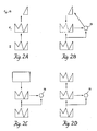
- the LTM traces of a subset template V are large only at a subset of the F1 nodes which are activated by the input pattern I ( Figure 6A).
- the LTM traces of a superset template V are large at all the F1 nodes which are activated by the input pattern I, as well as at some F1 nodes which are not activated by I ( Figure 6B).
- the LTM traces of a mixed template V are large at some, but not all, the F1 nodes which are activated by the input pattern I, as well as at some F1 nodes which are not activated by I ( Figure 6C).
- This subset recoding property is a key requirement for code stability.
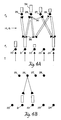
- Figure 7A summarizes a computer simulation of unstable code learning where the inhibitory top-down attentional gain control signals 42 are chosen too small for the 2/3 Rule to hold at F1.
- Figure 7B summarizes a computer simulation that illustrates how reinstatement of the 2/3 Rule can stabilize code learning. The format used in this figure will also be used in displaying our other computer simulations. We therefore describe this figure in detail.
- the first column of Figure 7A describes the four input patterns that were used in the simulation. These input patterns are labeled A, B, C, and D. Patterns B, C, and D are all subsets of A.
- Each of the Top-Down Template columns in Figure 7 corresponds to a different node in F2, with column 1 corresponding to node v1, column 2 corresponding to node v2, and so on.
- Each row summarizes the network response to its input pattern.
- the symbol RES which stands for resonance, designates the node in F2 which codes the input pattern on that trial. For example, v2 codes pattern C on trial 3, and v1 codes pattern B on trial 7.
- the patterns in a given row describe the templates after learning has occurred on that trial.
- Violation of the 2/3 Rule occurs on trials 4, 6, 8, 9, and so on. This violation is illustrated by comparing the template of v2 on trials 3 and 4.
- the template of v2 is coded by pattern C, which is a subset of pattern A.
- pattern A is presented and directly activates node v2. Because the 2/3 Rule does not hold, pattern A remains supraliminal, that is above threshold, in F1 even after the subset template C is read-out from v2. Thus no search is elicited by the mismatch of pattern A and its subset template C. Consequently the template of v2 is recoded from pattern C to its superset pattern A.
- each input pattern directly activates its node in F2 without undergoing any additional search.
- the "RES" symbol appears under the top-down templates.
- the patterns shown in any row between 9 and 15 provide a complete description of the learned code.
- the global structure of the input pattern determines which F2 nodes will be activated, and global measures of pattern match at F1 determine whether these nodes will be reset or allowed to resonate in STM.
- Nodes with superset templates are searched before uncommitted nodes due to the same property that guarantees direct access to perfectly coded nodes.
- initial bottom-up LTM values must be chosen small enough to permit direct access to nodes which perfectly code any input pattern.
- z0 is the maximal size of any initial bottom-up LTM trace
- ) ⁇ 1 is the learned LTM value corresponding to the superset template V (j) .
- the total bottom-up input to an uncommitted node in response to input I is thus at most Z0
- nodes v j which mixed templates satisfy (26) can possibly be searched. These nodes are searched in order of decreasing
- the network has already searched its subset templates.
- mixed templates but no superset templates, have previously been learned.
- the search can end by choosing either a node v i with a mixed template V (i) or a node which has not previously been chosen.
- a node v i with mixed template will be chosen before a new node if where z0 is the maximal initial size of the bottom-up LTM traces.
- z0 is the maximal initial size of the bottom-up LTM traces.
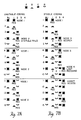
- FIGs 8 and 9 depict two coding sequences that illustrate the main points in the preceding discussion.
- each of nine input patterns was presented once.
- nodes v1 and v2 had already encoded subset templates of this input pattern.
- these nodes were therfore searched in order of decreasing template size.
- Nodes v3, v4, v5, and v6 had encoded mixed templates of the input pattern. These nodes were searched in the order v3, v5, v4.
- This search order was not detemined by template size per se, but was rather governed by the ratio
- the eight input patterns of Figure 9 were chosen to illustrate a search followed by coding of an uncommitted node.
- the last input pattern I in Figure 9 was the same as the last input pattern in Figure 8.
- the network first searched the nodes with subset templates in the order v2, v1.
- the mixed template nodes were searched in the order v4, v6, v5, v7.
- the mixed template node v3 was not searched because its template badly mismatched the input pattern I. Instead, the uncommitted node v8 was activated and learned a template that matched the input pattern.
- presentation of the novel input pattern does not immediately change the number of categories that are coded by the network, nor the set of nodes which code these categories in STM at F2.
- Output signals from F2 generate the network's observable responses.
- the novel pattern is assimilated into the previously established set of categorical alternatives and observable responses.
- At least two different types of learning can accompany such an assimilation process: learning that is external to the categorical recognition process and learning that is internal to this process.
- the 2/3 Rule implies, however, that the filters and templates of a category are subsets of all the input patterns that are coded by that category. Adding a new input pattern to a category through learning can only refine further the filters and templates of the category. Thus, after a template becomes a subset of an input pattern by coding that pattern, the template remains a subset of the input pattern for all future time, no matter how many times the template is refined as other input patterns join the same category. As a template becomes progressively finer, the mismatch between the template and the largest input patterns coded by its category becomes progressively greater. If this mismatch becomes too great, then some of these large input patterns may eventually be recoded.
- pattern B is coded by node v1 on trial 2, and no new categories are established. Later, however, when pattern A is next presented on trial 4, it can no longer adequately match the template from node v1, as it did after trial 1. Hence pattern A establishes a new category.
- the code learning process is one of progressive refinement of distinctions.
- the distinctions that emerge are the resultant of all the input patterns which the network ever experiences, rather than of some preassigned features.
- the matching process compares whole patterns, not just separate features. For example, two differenct templates may overlap an input pattern to F1 at the same set of feature detectors, yet the network could reset the F2 node of one template yet not reset the F2 node of the other template.
- the degree of mismatch of template and input as a whole determines whether recoding will occur.
- the learning of categorical invariants resolves two opposing tendencies.
- the next section describes how a sufficiently large mismatch between an input pattern and a template can lead to STM reset, while a sufficiently good match can terminate the search and enable learning to occur.
- the orienting subsystem will only trigger reset of F2 when the coincident pattern at F1 indicates an inadequate coincidence and when an input I is received from the buffer 12. Requirement that an input pattern be received allows the system to distinguish between a mismatch between an expected pattern and an input pattern and mere passive inactivity when no input pattern is received. On the other hand, when an input is received and a sufficient coincident pattern is generated at F1, reset of F2 by the orienting system A is inhibited by the coincident pattern.
- a bottom-up input pattern has activated F1 and blocked activation of A.
- F1 activates an F2 node which reads-out a template that badly mismatches the bottom-up input at F1.
- Due to the 2/3 Rule many of the F1 nodes which were activated by the bottom-up input alone are suppressed by the top-down template.
- this mismatch event causes a large collapse in the total activity across F1, and thus a large reduction in the total inhibition which F1 delivers to A. If this reduction is sufficiently large, then the excitatory bottom-up input to A may succeed in generating a nonspecific reset signal from A to F2.
- the 2/3 Rule implies that the total inhibitory signal from F1 to A equals ⁇ [V (j) ⁇ I
- the orienting subsystem is activated only if
- Inequality (32) shows that the Reset Function should be defined as follows: The Reset Function R j and the Order Function determine how the search will proceed.
- the rescaling property shows that the network processes input patterns as a whole.
- the functional units of the network are activation patterns across a field of feature detectors, rather than individual activations of feature detectors.
- the template of v1 is refined to equal the intersection V (1) ⁇ I (1) .
- the network accepts the evidence that I (1) should be coded by v1, it then suppresses as noise the features at which I (1) disagrees with V (1) , both in STM and in LTM.
- the network can also distinguish finer differences between small input patterns than between large input patterns.
- the amount of mismatch between a small input pattern I (1) and its template V (1) equals the amount of mismatch between a large input pattern I (2) and its template V (2) ; that is,
- v1 is more likely to be reset by I (1) than is v2 to be reset by I (2) .
- v1 offers more evidence for reset when the input pattern is simple than when it is complex. Otherwise expressed, since the network is reset by smaller mismatches when processing smaller input patterns, it automatically makes finer distinctions between smaller input patterns than between larger input patterns.
- the simulation in Figure 10 illustrates how the network automatically rescales its matching criterion.
- the patterns are presented in the order ABAB. By trial 2, coding is complete. Pattern A directly accesses node v1 on trial 3, and pattern B directly accesses node v2 on trial 4. Thus patterns A and B are coded within different categories.
- patterns C and D are presented in the order CDCD. Patterns C and D are constructed form patterns A and B, respectively, by adding identical upper halves to A and B. Thus, pattern C differs from pattern D at the same locations where pattern A differs from pattern B. However, because patterns C and D represent many more active features than patterns A and B, the difference between C and D is treated as noise, whereas the difference between A and B is considered significant. In particular, both patterns C and D are coded within the same category on trials 7 and 8.
- the network automatically rescales its sensitivity to patterns of variable complexity. Also, changes in the vigilance level can regulate the coarseness of the categories that are learned in response to a fixed sequence of input patterns.
- a low vigilance level leads to learning of coarse categories, whereas a high vigilance level leads to learning of fine categories.
- a low vigilance level has led to a learned grouping of inputs which need to be distinguished for successful adaptation to a prescribed input environment.
- a punishing event occurs through input 50 as a consequence of this erroneous grouping.
- Such a punishing event may have multiple effects.
- Such an increase in sensitivity is modelled within the network by an increase in the vigilance parameter, ⁇ . Increasing this single parameter enables the network to discriminate patterns which previously were lumped together. Once these patterns are coded by different categories in F2, the different categories can be associated with different behavioral responses.
- This teaching function does not take the form of an algorithm or any other type of pattern-specific information. Rather, it sets a single nonspecific parameter whose interaction with the internal organization of the network enables the network to parse more finely whatever input patterns happen to occur.
- the vigilance parameter will be increased, for example, if all the signals from the input pattern to A are nonspecifically amplified, so that parameter increases.
- a nonspecific decrease in the size of signals ⁇ from F1 to A will also increase ⁇ .
- reinforcement-activated nonspecific excitatory input to A can also facilitate mismatch-mediated activation of A.
- the process whereby the level of vigilance is monitored is one of the three types of nonspecific arousal that exist within the network.
- Figure 11 describes a series of simulations in which four input patterns, A, B, C, D, are coded by a network with four nodes in F2.
- the different parts of the figure show how categorical learning changes with changes of ⁇ .
- the simulation shows that any consecutive pair of patterns, (A,B), (B,C), (C,D), can be coded in the same category at different vigilance levels.
- This class of networks is capable of organizing arbitrary sequences of arbitrarily complex input patterns into stable categories subject to the constraints of vigilance, global code self-consistency, and number of nodes in F1 and F2. If slow learning rather than fast learning rates are used, then the categorical code may be learned more slowly but it still enjoys the critical properties just listed.
Landscapes
- Engineering & Computer Science (AREA)
- Data Mining & Analysis (AREA)
- Physics & Mathematics (AREA)
- Theoretical Computer Science (AREA)
- Bioinformatics & Cheminformatics (AREA)
- Artificial Intelligence (AREA)
- Life Sciences & Earth Sciences (AREA)
- Bioinformatics & Computational Biology (AREA)
- Computer Vision & Pattern Recognition (AREA)
- Evolutionary Biology (AREA)
- Evolutionary Computation (AREA)
- General Engineering & Computer Science (AREA)
- General Physics & Mathematics (AREA)
- Probability & Statistics with Applications (AREA)
- Image Analysis (AREA)
Claims (19)
- Ein selbstorganisierendes Mustererkennungssystem zur Identifikation und Kategorisierung eines Eingabemusters, mit einem oder mehreren identifizierbaren Elementen, umfassend:
eine Mustererzeugungseinheit (F1) zum Empfangen des Eingabemusters (12) und zum Erzeugen eines Ausgabemusters als Antwort auf die Elemente des Eingabemusters;
anpassungsfähige Filtermittel (14) für das Wichten einzelner Elemente des Ausgabemusters in bezug auf jede einer Mehrzahl von Musterkategorien;
eine Kategorie-Auswahl-Einheit (F2) zur Auswahl wenigstens einer Musterkategorie als Antwort auf Kombinationen gewichteter Elemente;
Schablonenmittel (16) zum Erzeugen und Liefern einer Schablone oder eines erwarteten Musters als Antwort auf wenigstens eine ausgewählte Musterkategorie an die Mustererzeugungseinheit (F1);
Mittel zur Erzeugung einer Determinante (18), die auf die Übereinstimmung der Elemente zwischen dem Eingabemuster und dem erwarteten Muster bezogen ist; und
Mittel zum Modifizieren der Wichtung der Elemente des Ausgabemusters und des erwarteten Musters in bezug auf die wenigstens eine, ausgewählte Musterkategorie, so daß da, wo die Determinante einen Schwellenwert überschreitet, das Mittel zum Modifizieren befähigt ist, Elemente, welche ein modifiziertes, erwartetes Muster definieren, in Verbindung mit dem Eingabemuster und dem erwarteten Muster zurückzubehalten und alle anderen dieser Elemente nicht zu betonen, und dort, wo es der Determinante mißlingt, den Schwellenwert zu überschreiten, das Mittel zum Modifizieren befähigt ist, eine alternative Musterkategorie auszuwählen, so daß ein neues erwartetes Muster erzeugt werden kann, wobei die alternative Musterkategorie benutzt wird. - Ein System nach Anspruch 1, bei dem die Determinante von einem übereinstimmenden Muster erzeugt wird, welches ein Muster von Elementen ist, die dem Eingabemuster und dem erwarteten Muster gemeinsam sind.
- Ein System nach Anspruch 2, bei dem die Mittel zum Erzeugen der Determinante Mittel umfassen, zum Bestimmen der Anzahl der Elemente in dem übereinstimmenden Muster in bezug auf die Anzahl der Elemente in dem Eingabemuster.
- Ein System nach einem der Ansprüche 2 oder 3, bei dem die Mittel zum Modifizieren Mittel einschließen, zum Reduzieren der Wichtung der nicht in dem übereinstimmenden Muster vorhandenen Elemente bis annähernd Null in bezug auf wenigstens eine ausgewählte Musterkategorie.
- Ein System nach einem der Ansprüche 2 bis 4, bei dem das übereinstimmende Muster das Eingabemuster ist, wenn kein erwartetes Muster erzeugt ist und das übereinstimmende Muster ein Muster von Elementen ist, die dem Eingabemuster und dem erwarteten Muster gemeinsam sind, wenn ein erwartetes Muster erzeugt ist.
- Ein System nach Anspruch 5, bei dem die Elemente des Musters binäre Werte sind, und das übereinstimmende Muster ein Schnitt zwischen dem Eingabemuster und dem erwarteten Muster ist, wenn ein erwartetes Muster erzeugt ist.
- Ein System nach einem der Ansprüche 2 bis 6, bei dem der Schwellenwert ein vorbestimmtes Verhältnis der Anzahl der Elemente in dem übereinstimmenden Muster in bezug auf die Anzahl der Elemente in dem Eingabemuster ist.
- Ein System nach einem der Ansprüche 2 bis 7, bei dem die Kategorie-Auswahl-Einheit (F2) eine Musterkategorie auswählt, gemäß dem Verhältnis von (a) dem Produkt einer Konstanten α und der Anzahl der Elemente in dem übereinstimmenden Muster zu (b) der Summe einer Konstanten β und der Anzahl der Elemente in dem erwarteten Muster.
- Ein System nach einem der voranstehenden Ansprüche, bei dem die Kategorie-Auswahl-Einheit (F2) lediglich die einzelne Musterkategorie auswählt, welche die größte Summe gewichteter Elemente des Ausgabemusters aufweist.
- Ein System nach einem der voranstehenden Ansprüche, bei dem die Mittel zum Modifizieren die Wichtung der Elemente des Ausgabemusters in den anpassungsfähigen Filtermitteln im umgekehrten Verhältnis zu der Anzahl der Elemente, die dem Eingabemuster und dem erwarteten Muster gemeinsam sind, ändern.
- Ein System nach Anspruch 10, bei dem die inverse Beziehung von der Form ist:

- Ein System nach einem der voranstehenden Ansprüche, bei dem die anfängliche Wichtung aller möglichen Elemente in dem Ausgabemuster niedrig ist.
- Ein System nach Anspruch 12, bei dem die anfängliche Wichtung aller möglichen Elemente in dem Ausgabemuster unterschiedlich für unterschiedliche Musterkategorien ist.
- Ein System nach einem der voranstehenden Ansprüche, welches ferner Mittel (50) umfaßt zum Ändern des Schwellenwertes, der als Modifikation der anpassungsfähigen Filtermittel und der Schablonenmittel resultiert.
- Ein System nach einem der voranstehenden Ansprüche, umfassend Mittel zur Auswahl einer weiteren Musterkategorie vor dem Empfang eines weiteren Eingabemusters durch das System, um ein Eingabemuster vorwegzunehmen, entsprechend einer ausgewählten, weiteren Musterkategorie, die von einem vorhergehenden Eingabemuster abhängt.
- Ein Verfahren zur Mustererkennung durch Identifikation und Kategorisierung eines Eingabemusters mit einem oder mehreren identifizierbaren Elementen, umfassend:
Zuliefern des Eingabemusters an eine Mustererzeugungseinheit (F1), die als Antwort auf die Elemente des Eingabemusters ein Ausgabemuster erzeugt;
einzelnes Wichten der Elemente (14) des Ausgabemusters in bezug auf jede einer Vielzahl von Musterkategorien;
Auswählen wenigstens einer Musterkategorie (F2), basierend auf Kombinationen der gewichteten Elemente;
Erzeugen (16) und Zuliefern an die Mustererzeugungseinheit (F1) einer Schablone oder eines erwarteten Musters als Antwort auf wenigstens eine ausgewählte Musterkategorie;
Erzeugen einer Determinante (18), die auf die Übereinstimmung der Elemente zwischen dem Eingabemuster und dem erwarteten Muster bezogen ist und Feststellen, ob die Determinante einen Schwellenwert überschreitet; und
wenn die Determinante einen Schwellenwert überschreitet, Modifizieren der Wichtung der Elemente des Ausgabemusters und der Elemente des erwarteten Musters in bezug auf die wenigstens eine ausgewählte Musterkategorie, um Elemente zurückzubehalten, die ein modifiziertes erwartetes Muster definieren in Verbindung mit dem Eingabemuster und dem erwarteten Muster und um alle anderen solche Elemente nicht zu betonen und, wenn es der Determinante mißlingt, den Schwellenwert zu überschreiten, Auswählen einer alternativen Musterkategorie und Verwenden der alternativen ausgewählten Musterkategorie, um neue erwartete Muster zu erzeugen. - Ein Verfahren nach Anspruch 16, bei dem die Determinante von einem übereinstimmenden Muster erzeugt wird, welches ein Muster von Elementen ist, die dem Eingabemuster und dem erwarteten Muster gemeinsam ist.
- Ein Verfahren nach einem der Ansprüche 16 oder 17, bei dem die Determinante durch Bestimmen der Anzahl der Elemente erzeugt wird, die dem Eingabemuster und dem erwarteten Muster in bezug auf die Anzahl der Elemente in dem Eingabemuster gemeinsam sind.
- Ein Verfahren nach einem der Ansprüche 16 bis 18, bei dem die Wichtung der Elemente des Ausgabemusters in umgekehrtem Verhältnis zu der Anzahl der Elemente modifiziert wird, die dem Eingabemuster und dem Ausgabemuster gemeinsam sind.
Applications Claiming Priority (2)
| Application Number | Priority Date | Filing Date | Title |
|---|---|---|---|
| US80257685A | 1985-11-27 | 1985-11-27 | |
| US802576 | 1985-11-27 |
Publications (2)
| Publication Number | Publication Date |
|---|---|
| EP0244483A1 EP0244483A1 (de) | 1987-11-11 |
| EP0244483B1 true EP0244483B1 (de) | 1992-07-15 |
Family
ID=25184098
Family Applications (1)
| Application Number | Title | Priority Date | Filing Date |
|---|---|---|---|
| EP87900750A Expired EP0244483B1 (de) | 1985-11-27 | 1986-11-26 | Mustererkennungssystem |
Country Status (5)
| Country | Link |
|---|---|
| US (1) | US5142590A (de) |
| EP (1) | EP0244483B1 (de) |
| JP (1) | JP2517036B2 (de) |
| DE (1) | DE3686051T2 (de) |
| WO (1) | WO1987003399A1 (de) |
Cited By (3)
| Publication number | Priority date | Publication date | Assignee | Title |
|---|---|---|---|---|
| US5566092A (en) * | 1993-12-30 | 1996-10-15 | Caterpillar Inc. | Machine fault diagnostics system and method |
| US5566273A (en) * | 1993-12-30 | 1996-10-15 | Caterpillar Inc. | Supervised training of a neural network |
| US5602761A (en) * | 1993-12-30 | 1997-02-11 | Caterpillar Inc. | Machine performance monitoring and fault classification using an exponentially weighted moving average scheme |
Families Citing this family (54)
| Publication number | Priority date | Publication date | Assignee | Title |
|---|---|---|---|---|
| WO1987003398A1 (en) | 1985-11-27 | 1987-06-04 | The Trustees Of Boston University | Neural networks for machine vision |
| US4914708A (en) * | 1987-06-19 | 1990-04-03 | Boston University | System for self-organization of stable category recognition codes for analog input patterns |
| JPH0679340B2 (ja) * | 1987-07-15 | 1994-10-05 | 新技術事業団 | パタ−ン認識装置 |
| CA1318977C (en) * | 1987-07-22 | 1993-06-08 | Kazuhito Hori | Image recognition system |
| JPH03286247A (ja) * | 1990-03-31 | 1991-12-17 | Toshiba Corp | 神経回路網処理方式 |
| JPH0438587A (ja) * | 1990-06-04 | 1992-02-07 | Nec Corp | 入力領域適応型ニューラルネットワーク文字認識装置 |
| US5157738A (en) * | 1990-12-18 | 1992-10-20 | Trustees Of Boston University | Rapid category learning and recognition system |
| US5485621A (en) * | 1991-05-10 | 1996-01-16 | Siemens Corporate Research, Inc. | Interactive method of using a group similarity measure for providing a decision on which groups to combine |
| EP0513652A2 (de) * | 1991-05-10 | 1992-11-19 | Siemens Aktiengesellschaft | Verfahren zur Modellierung einer Ähnlichkeitsfunktion mittels eines Neuronalnetzes |
| US5438676A (en) * | 1991-05-10 | 1995-08-01 | Siemens Corporate Research, Inc. | Method for adapting a similarity function for identifying misclassified software objects |
| US5440742A (en) * | 1991-05-10 | 1995-08-08 | Siemens Corporate Research, Inc. | Two-neighborhood method for computing similarity between two groups of objects |
| US5317741A (en) * | 1991-05-10 | 1994-05-31 | Siemens Corporate Research, Inc. | Computer method for identifying a misclassified software object in a cluster of internally similar software objects |
| US5428788A (en) * | 1991-05-10 | 1995-06-27 | Siemens Corporate Research, Inc. | Feature ratio method for computing software similarity |
| RU2037203C1 (ru) * | 1993-07-16 | 1995-06-09 | Ольга Олеговна Веровенко | Способ идентификации объектов |
| US6122405A (en) * | 1993-08-27 | 2000-09-19 | Martin Marietta Corporation | Adaptive filter selection for optimal feature extraction |
| ES2103176B1 (es) * | 1994-05-13 | 1998-04-01 | Consejo Superior Investigacion | Circuito para el reconocimiento y establecimiento de categorias de patrones binarios. |
| TW274135B (de) * | 1994-09-14 | 1996-04-11 | Hitachi Seisakusyo Kk | |
| US5654762A (en) * | 1995-05-01 | 1997-08-05 | Tektronix, Inc. | Block matching for picture motion estimation using gray codes |
| US5912700A (en) * | 1996-01-10 | 1999-06-15 | Fox Sports Productions, Inc. | System for enhancing the television presentation of an object at a sporting event |
| US7714778B2 (en) | 1997-08-20 | 2010-05-11 | Tracbeam Llc | Wireless location gateway and applications therefor |
| US7903029B2 (en) | 1996-09-09 | 2011-03-08 | Tracbeam Llc | Wireless location routing applications and architecture therefor |
| US6236365B1 (en) | 1996-09-09 | 2001-05-22 | Tracbeam, Llc | Location of a mobile station using a plurality of commercial wireless infrastructures |
| US9134398B2 (en) | 1996-09-09 | 2015-09-15 | Tracbeam Llc | Wireless location using network centric location estimators |
| WO1998010307A1 (en) | 1996-09-09 | 1998-03-12 | Dennis Jay Dupray | Location of a mobile station |
| US7274332B1 (en) | 1996-09-09 | 2007-09-25 | Tracbeam Llc | Multiple evaluators for evaluation of a purality of conditions |
| US6249252B1 (en) | 1996-09-09 | 2001-06-19 | Tracbeam Llc | Wireless location using multiple location estimators |
| US5842164A (en) * | 1996-10-21 | 1998-11-24 | Batl Software Systems Ltd. | Dynamic pattern recognition system |
| US5917553A (en) * | 1996-10-22 | 1999-06-29 | Fox Sports Productions Inc. | Method and apparatus for enhancing the broadcast of a live event |
| US6535681B2 (en) * | 2001-06-19 | 2003-03-18 | Lucent Technologies Inc. | Fiber-optic cable routing and bend limiting device and system |
| US5953077A (en) * | 1997-01-17 | 1999-09-14 | Fox Sports Productions, Inc. | System for displaying an object that is not visible to a camera |
| DE19803127A1 (de) * | 1998-01-28 | 1999-08-05 | Foerderung Angewandter Informa | Verfahren und Vorrichtung zum Zusammenfügen von durch Aktenvernichter in Streifen zerlegten Seiten |
| US6516309B1 (en) * | 1998-07-17 | 2003-02-04 | Advanced Research & Technology Institute | Method and apparatus for evolving a neural network |
| US6343376B1 (en) * | 1998-10-22 | 2002-01-29 | Computer Computer Corporation | System and method for program verification and optimization |
| US8135413B2 (en) | 1998-11-24 | 2012-03-13 | Tracbeam Llc | Platform and applications for wireless location and other complex services |
| US6546117B1 (en) | 1999-06-10 | 2003-04-08 | University Of Washington | Video object segmentation using active contour modelling with global relaxation |
| US6272250B1 (en) | 1999-01-20 | 2001-08-07 | University Of Washington | Color clustering for scene change detection and object tracking in video sequences |
| US6480615B1 (en) * | 1999-06-15 | 2002-11-12 | University Of Washington | Motion estimation within a sequence of data frames using optical flow with adaptive gradients |
| WO2002000316A1 (en) | 1999-09-24 | 2002-01-03 | Goldberg Sheldon F | Geographically constrained network services |
| GB0005881D0 (en) * | 2000-03-10 | 2000-05-03 | Surface Inspection Ltd | A classification space packing scheme, and an inspection apparatus using the classification method |
| US7942828B2 (en) * | 2000-05-17 | 2011-05-17 | The Mclean Hospital Corporation | Method for determining fluctuation in attentional state and overall attentional state |
| CA2410041C (en) | 2000-05-17 | 2013-07-09 | The Mclean Hospital Corporation | Method for determining fluctuation in attentional state and overall attentional state |
| US10684350B2 (en) | 2000-06-02 | 2020-06-16 | Tracbeam Llc | Services and applications for a communications network |
| US10641861B2 (en) | 2000-06-02 | 2020-05-05 | Dennis J. Dupray | Services and applications for a communications network |
| US9875492B2 (en) | 2001-05-22 | 2018-01-23 | Dennis J. Dupray | Real estate transaction system |
| US6639614B1 (en) | 2000-07-10 | 2003-10-28 | Stephen Michael Kosslyn | Multi-variate data presentation method using ecologically valid stimuli |
| US7036115B2 (en) * | 2001-01-08 | 2006-04-25 | Hewlett-Packard Development Company, L.P. | Code generation by matching and satisfiability search |
| US8082096B2 (en) | 2001-05-22 | 2011-12-20 | Tracbeam Llc | Wireless location routing applications and architecture therefor |
| US7945627B1 (en) | 2006-09-28 | 2011-05-17 | Bitdefender IPR Management Ltd. | Layout-based electronic communication filtering systems and methods |
| JP4641537B2 (ja) | 2007-08-08 | 2011-03-02 | 株式会社日立製作所 | データ分類方法および装置 |
| US8572184B1 (en) | 2007-10-04 | 2013-10-29 | Bitdefender IPR Management Ltd. | Systems and methods for dynamically integrating heterogeneous anti-spam filters |
| US8010614B1 (en) | 2007-11-01 | 2011-08-30 | Bitdefender IPR Management Ltd. | Systems and methods for generating signatures for electronic communication classification |
| EP2263150A2 (de) * | 2008-02-27 | 2010-12-22 | Tsvi Achler | Feedback-systeme und verfahren zur erkennung von mustern |
| US8131655B1 (en) | 2008-05-30 | 2012-03-06 | Bitdefender IPR Management Ltd. | Spam filtering using feature relevance assignment in neural networks |
| US9538493B2 (en) | 2010-08-23 | 2017-01-03 | Finetrak, Llc | Locating a mobile station and applications therefor |
Family Cites Families (13)
| Publication number | Priority date | Publication date | Assignee | Title |
|---|---|---|---|---|
| NL265383A (de) * | 1960-05-31 | |||
| US3191149A (en) * | 1962-01-15 | 1965-06-22 | Ibm | Specimen identification apparatus with means for altering stored specimen reference functions |
| FR2191788A5 (de) * | 1972-06-30 | 1974-02-01 | Honeywell Bull | |
| US3950733A (en) * | 1974-06-06 | 1976-04-13 | Nestor Associates | Information processing system |
| US4044243A (en) * | 1976-07-23 | 1977-08-23 | Nestor Associates | Information processing system |
| US4177448A (en) * | 1978-06-26 | 1979-12-04 | International Business Machines Corporation | Character recognition system and method multi-bit curve vector processing |
| JPS5819109B2 (ja) * | 1978-11-10 | 1983-04-16 | 肇産業株式会社 | パタ−ン判別方法 |
| US4254474A (en) * | 1979-08-02 | 1981-03-03 | Nestor Associates | Information processing system using threshold passive modification |
| US4319331A (en) * | 1980-01-28 | 1982-03-09 | Nestor Associates | Curve follower |
| US4326259A (en) * | 1980-03-27 | 1982-04-20 | Nestor Associates | Self organizing general pattern class separator and identifier |
| US4606069A (en) * | 1983-06-10 | 1986-08-12 | At&T Bell Laboratories | Apparatus and method for compression of facsimile information by pattern matching |
| US4773099A (en) * | 1985-10-10 | 1988-09-20 | The Palantir Corporation | Pattern classification means for use in a pattern recognition system |
| US4805225A (en) * | 1986-11-06 | 1989-02-14 | The Research Foundation Of The State University Of New York | Pattern recognition method and apparatus |
-
1986
- 1986-11-26 EP EP87900750A patent/EP0244483B1/de not_active Expired
- 1986-11-26 WO PCT/US1986/002553 patent/WO1987003399A1/en not_active Ceased
- 1986-11-26 JP JP62500847A patent/JP2517036B2/ja not_active Expired - Lifetime
- 1986-11-26 DE DE8787900750T patent/DE3686051T2/de not_active Expired - Lifetime
-
1991
- 1991-01-22 US US07/644,685 patent/US5142590A/en not_active Expired - Lifetime
Cited By (3)
| Publication number | Priority date | Publication date | Assignee | Title |
|---|---|---|---|---|
| US5566092A (en) * | 1993-12-30 | 1996-10-15 | Caterpillar Inc. | Machine fault diagnostics system and method |
| US5566273A (en) * | 1993-12-30 | 1996-10-15 | Caterpillar Inc. | Supervised training of a neural network |
| US5602761A (en) * | 1993-12-30 | 1997-02-11 | Caterpillar Inc. | Machine performance monitoring and fault classification using an exponentially weighted moving average scheme |
Also Published As
| Publication number | Publication date |
|---|---|
| JP2517036B2 (ja) | 1996-07-24 |
| EP0244483A1 (de) | 1987-11-11 |
| DE3686051D1 (de) | 1992-08-20 |
| WO1987003399A1 (en) | 1987-06-04 |
| US5142590A (en) | 1992-08-25 |
| DE3686051T2 (de) | 1992-12-17 |
| JPS63501455A (ja) | 1988-06-02 |
Similar Documents
| Publication | Publication Date | Title |
|---|---|---|
| EP0244483B1 (de) | Mustererkennungssystem | |
| Vilalta et al. | A perspective view and survey of meta-learning | |
| EP0367790B1 (de) | Kategorie-erkennungssystem für analogbilder | |
| EP0569549B1 (de) | Praediktives selbst-organisierendes neuronales netzwerk | |
| Cao et al. | Projective ART for clustering data sets in high dimensional spaces | |
| Gutta et al. | Face recognition using hybrid classifiers | |
| Younes et al. | Color image profiling using fuzzy sets | |
| Rokach et al. | Selective voting—getting more for less in sensor fusion | |
| Ferecatu et al. | Interactive search for image categories by mental matching | |
| Gançarski et al. | Collaborative multi-step mono-level multi-strategy classification | |
| Nasuto et al. | Communication as an emergent metaphor for neuronal operation | |
| Nolan | Computer systems that learn: an empirical study of the effect of noise on the performance of three classification methods | |
| Frigui et al. | Unsupervised clustering and feature discrimination with application to image database categorization | |
| Kotsiantis et al. | Selective voting | |
| Canuto et al. | Investigating the use of an agent-based multi-classifier system for classification tasks | |
| US6629088B1 (en) | Method and apparatus for measuring the quality of descriptors and description schemes | |
| Santoshi et al. | Recognition of Handwritten Digit Using Neural Networks | |
| Chang et al. | A new method to generate fuzzy rules from numerical data based on the exclusion of attribute terms | |
| Carpenter et al. | ART 2: self-organization of stable category recognition codes for analog input patterns | |
| Graef et al. | Application of art2 networks and self-organizing maps to collaborative filtering | |
| Aha | An implementation and experiment with the nested generalized exemplars algorithm | |
| Magdalena | Adapting gain and sensibility of FLCs with genetic algorithms | |
| Paris-Nord | Color Image Profiling Using Fuzzy Sets | |
| Knopf | Data fusion using a hierarchy of self-organizing feature maps | |
| Lecourtier et al. | MLP modular versus yprel classifiers |
Legal Events
| Date | Code | Title | Description |
|---|---|---|---|
| PUAI | Public reference made under article 153(3) epc to a published international application that has entered the european phase |
Free format text: ORIGINAL CODE: 0009012 |
|
| 17P | Request for examination filed |
Effective date: 19870727 |
|
| AK | Designated contracting states |
Kind code of ref document: A1 Designated state(s): DE FR GB |
|
| 17Q | First examination report despatched |
Effective date: 19900403 |
|
| GRAA | (expected) grant |
Free format text: ORIGINAL CODE: 0009210 |
|
| AK | Designated contracting states |
Kind code of ref document: B1 Designated state(s): DE FR GB |
|
| REF | Corresponds to: |
Ref document number: 3686051 Country of ref document: DE Date of ref document: 19920820 |
|
| ET | Fr: translation filed | ||
| PLBE | No opposition filed within time limit |
Free format text: ORIGINAL CODE: 0009261 |
|
| STAA | Information on the status of an ep patent application or granted ep patent |
Free format text: STATUS: NO OPPOSITION FILED WITHIN TIME LIMIT |
|
| 26N | No opposition filed | ||
| PGFP | Annual fee paid to national office [announced via postgrant information from national office to epo] |
Ref country code: FR Payment date: 19991117 Year of fee payment: 14 |
|
| PGFP | Annual fee paid to national office [announced via postgrant information from national office to epo] |
Ref country code: GB Payment date: 19991123 Year of fee payment: 14 |
|
| PGFP | Annual fee paid to national office [announced via postgrant information from national office to epo] |
Ref country code: DE Payment date: 19991223 Year of fee payment: 14 |
|
| PG25 | Lapsed in a contracting state [announced via postgrant information from national office to epo] |
Ref country code: GB Free format text: LAPSE BECAUSE OF NON-PAYMENT OF DUE FEES Effective date: 20001126 |
|
| GBPC | Gb: european patent ceased through non-payment of renewal fee |
Effective date: 20001126 |
|
| PG25 | Lapsed in a contracting state [announced via postgrant information from national office to epo] |
Ref country code: FR Free format text: LAPSE BECAUSE OF NON-PAYMENT OF DUE FEES Effective date: 20010731 |
|
| PG25 | Lapsed in a contracting state [announced via postgrant information from national office to epo] |
Ref country code: DE Free format text: LAPSE BECAUSE OF NON-PAYMENT OF DUE FEES Effective date: 20010801 |
|
| REG | Reference to a national code |
Ref country code: FR Ref legal event code: ST |