EP0244220A1 - Grassammelsystem für Mäher - Google Patents
Grassammelsystem für Mäher Download PDFInfo
- Publication number
- EP0244220A1 EP0244220A1 EP87303798A EP87303798A EP0244220A1 EP 0244220 A1 EP0244220 A1 EP 0244220A1 EP 87303798 A EP87303798 A EP 87303798A EP 87303798 A EP87303798 A EP 87303798A EP 0244220 A1 EP0244220 A1 EP 0244220A1
- Authority
- EP
- European Patent Office
- Prior art keywords
- shield
- reel
- air duct
- air
- auger
- Prior art date
- Legal status (The legal status is an assumption and is not a legal conclusion. Google has not performed a legal analysis and makes no representation as to the accuracy of the status listed.)
- Withdrawn
Links
Images


Classifications
-
- A—HUMAN NECESSITIES
- A01—AGRICULTURE; FORESTRY; ANIMAL HUSBANDRY; HUNTING; TRAPPING; FISHING
- A01D—HARVESTING; MOWING
- A01D34/00—Mowers; Mowing apparatus of harvesters
- A01D34/01—Mowers; Mowing apparatus of harvesters characterised by features relating to the type of cutting apparatus
- A01D34/412—Mowers; Mowing apparatus of harvesters characterised by features relating to the type of cutting apparatus having rotating cutters
- A01D34/42—Mowers; Mowing apparatus of harvesters characterised by features relating to the type of cutting apparatus having rotating cutters having cutters rotating about a horizontal axis, e.g. cutting-cylinders
- A01D34/49—Mowers; Mowing apparatus of harvesters characterised by features relating to the type of cutting apparatus having rotating cutters having cutters rotating about a horizontal axis, e.g. cutting-cylinders with means for discharging mown material
-
- A—HUMAN NECESSITIES
- A01—AGRICULTURE; FORESTRY; ANIMAL HUSBANDRY; HUNTING; TRAPPING; FISHING
- A01D—HARVESTING; MOWING
- A01D43/00—Mowers combined with apparatus performing additional operations while mowing
- A01D43/06—Mowers combined with apparatus performing additional operations while mowing with means for collecting, gathering or loading mown material
-
- A—HUMAN NECESSITIES
- A01—AGRICULTURE; FORESTRY; ANIMAL HUSBANDRY; HUNTING; TRAPPING; FISHING
- A01D—HARVESTING; MOWING
- A01D75/00—Accessories for harvesters or mowers
- A01D75/30—Arrangements for trailing two or more mowers
-
- A—HUMAN NECESSITIES
- A01—AGRICULTURE; FORESTRY; ANIMAL HUSBANDRY; HUNTING; TRAPPING; FISHING
- A01D—HARVESTING; MOWING
- A01D2101/00—Lawn-mowers
-
- A—HUMAN NECESSITIES
- A01—AGRICULTURE; FORESTRY; ANIMAL HUSBANDRY; HUNTING; TRAPPING; FISHING
- A01D—HARVESTING; MOWING
- A01D34/00—Mowers; Mowing apparatus of harvesters
- A01D34/01—Mowers; Mowing apparatus of harvesters characterised by features relating to the type of cutting apparatus
- A01D34/412—Mowers; Mowing apparatus of harvesters characterised by features relating to the type of cutting apparatus having rotating cutters
- A01D34/42—Mowers; Mowing apparatus of harvesters characterised by features relating to the type of cutting apparatus having rotating cutters having cutters rotating about a horizontal axis, e.g. cutting-cylinders
Definitions
- This invention relates to improved means in a reel mower for picking up cut grass.
- Reel mowers are commonly used for cutting grass where an accurate cut and a fine finished appearance for the cut grass are required, e.g. on golf courses. In such areas it is common to pick up the clippings in order to improve the aesthetic appearance of the cut area and to prevent accumulation of thatch in the grass.
- the reel mower has a number of gangs (i.e. separate reel mowers attached to a single vehicle), it is not usually practical to attach a separate pickup basket to each gang. Therefore at the present time clippings are commonly picked up by providing a separate vehicle, fitted either with a sweeper or a vacuum, which travels over the grass area after it has been cut and picks up the clippings.
- Such clean up vehicles are expensive and the separate clean up operation is time consuming and costly.
- reel mower grass collection apparatus comprising:
- the present invention provides reel mower apparatus as above recited, and further including air duct means coupled to said shield for receiving clippings from said mechanical conveying means, and means for generating an airstream in said air duct means to convey away said grass clippings delivered to said air duct means by said mechanical conveying means and wherein said air duct means is coupled to said shield at a collection location, said mechanical conveying means including means for feeding cut grass clippings across said reel into said air duct means at said collection location, said air duct means including an air feed opening therein adjacent said collection location to allow outside air to enter said air duct means adjacent said collection location, to help ensure a continually flowing airstream through said air duct means past said collection location and thereby to help ensure that should said mechanical conveying means become filled with grass clippings preventing an airflow therethrough, said clippings will none-the-less tend always to be dumped by said mechanical conveying means into said continually flowing airstream.
- Fig. 1 shows a vehicle generally indicated at 10 which is adapted to travel forwardly in the direction of arrow 12.
- the vehicle 10 includes a frame 14, four support and drive wheels 16, and a motor (not shown) beneath an operator seat 20.
- the vehicle 10 also has a steering wheel 22, and controls diagrammatically indicated at 24. It also includes a large cut grass storage hopper 26 having a rear emptying door 28 which is normally closed by a latch 30.
- a mechanical or hydraulic mechanism can be provided to open the door 28 when desired.
- the vehicle 10 supports two front gangs or reel mowers 32, 34 and three rear gangs or reel mowers 36, 38, 40 of which only two are shown in Fig. 1. Portions of all three rear reel mowers 36, 38, 40 are indicated in Fig. 2.
- each reel mower 32 to 40 is preferably of the construction shown in my co-pending Canadian patent application serial No. 437,066 filed September 20, 1983, and the description of that application is hereby incorporated by reference.
- each reel mower 32 to 40 includes a frame having a pair of end plates 42 and a top plate 44 extending between the end plates over the top of the mower.
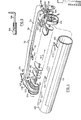
- Each mower 32 to 40 includes a reel 46 having spiral blades 48 and support disks 50 mounted on a reel tube 52.
- the reel tube 52 is rotatably mounted on an inner reel shaft 53 ( F ig. 6) which is secured to the mower frame end plates 42.
- the mower frame end plates 42 are supported by a U -shaped bracket 54 having an upper section 56 which extends over the top of the mower, and downwardly depending ends 58 which are pivotally connected at 60 to the ends of the reel shaft (not shown) which extend through the reel tube 52.
- the mower can pivot slightly or float on the bracket 54.
- Each mower is supported by a tubular arm 62 having an inner forked end 64 which is pivotally connected at 66 to plates 68 projecting from the vehicle 10.
- the tubular arm 62 has a forked outer end 70 which is connected to stub shafts 72 on the arm 56. This allows each arm 56, with its attached mower, to be pivoted about connection 66 and hence raised at its outboard end (by a piston and cylinder, not shown) during travel of the vehicle from one mowing location to another. It also allows each mower to pivot from side to side about a fore and aft axis through stub shafts 72 (the stub shafts 72 are normally located at approximately the lateral center of gravity of the mower).
- Each mower is driven by a drive shaft 74 which extends from the vehicle to a universal joint 76.
- the universal joint 76 is connected to a second telescopic drive shaft 78 which extends through the tubular arm 62.
- the second drive shaft 78 is connected by a further universal joint 80 to an outer drive shaft 82 which extends across the top of the mower and carries at its outer end a pulley 84 which drives each reel.
- the front mowers 32, 34 are driven through a common shaft inside housing 86 on the vehicle 10.
- the rear mowers are driven by other power outputs on the vehicle 10.
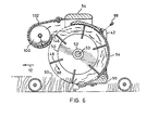
- a curved rear shield 94 extends across the width of the mower and rests at its bottom on the support 96 for the bed knife.
- the shield 94 is secured at its top by a pair of screws 98 which protrude one into each mower end plate 42.
- the rear shield 94 prevents grass clippings from exiting from the rear of the mower and causes the clippings to be carried upwardly and forwardly to a front grass collection means, now to be described.
- the grass collection means for each mower includes an auger 100 extending laterally across the width of each mower.
- Each auger 100 includes a conventional spiral flight 102 mounted on an auger shaft 104.
- the auger shaft 104 is supported at one end (see Figs. 4 and 5) by an L-shaped support shaft 106 the outer end of which protrudes through slot 108 in support bar 110 and is held in place by nut 112.
- the support bar 110 is welded to a ring 114 which in turn is welded to a pair of brackets 116, 117.
- Bracket 116 is bolted by bolts 118 to the U-shaped mower support bracket 54.
- the other end of the auger 100 is supported by a bearing 120 mounted in an end plate 122 which is bolted to the U-shaped bracket 54 by bolts 124.
- the auger 100 is driven by a sprocket 126 located on the outside of end plate 122.
- Sprocket 126 is connected by a chain 128 to another sprocket 130 on the end of the mower outer drive shaft 82.
- each shield 132 extends forwardly and downwardly around its associated auger 100 and then extends upwardly, ending in a lip 146 which is preferably just above a horizontal diameter through the auger 100.
- Each auger 100 is shaped so that when it rotates, it delivers cut grass from the closed end of the auger shield 132 (i.e. from end plate 122) to the open end at ring 114 (as indicated by arrow 147 in Fig. 4).
- the reel 46 of each mower is also preferably shaped (i.e. the twist of its spiral blades 48 is arranged) so that it tends to deliver grass towards the same direction as the auger 100.
- the auger (not shown) in shield 132 of mower 32 will deliver cut grass from right to left as drawn, and the reel 46 therein is rotated in the direction of arrow 88 to move the grass flow towards the same direction. This requires the reels on each side of the mower to be of opposite hands.
- the air conveyor system comprises a duct 148 which extends from between the two auger shields 132 in front mowers 32, 34 rearwardly to an impeller 150. From the impeller 150 a second duct 152 extends rearwardly into the storage container 26. Another duct 154 extends from between the two auger shields 132 of the rear mowers 38, 40 rearwardly to a second impeller 156. From impeller 156 another duct 158 extends to the storage container 26.
- the two impellers 150, 156 are mounted on a common shaft 160 driven by pulleys 162, 164 and a belt 168.
- the pulley 164 is connected to the main drive train (not shown) of the vehicle 10.
- a third duct 170 branches from the duct 148 into the open end of the shield 132 of mower 38, to convey cut grass from that mower.
- the duct 148 at its front end terminates in a transverse duct section 172 which is of elliptical cross section, with its major axis extending vertically.
- the top portion of the duct section 172 is inset at each end thereof, as shown at 174, leaving a protruding bottom half-trough 176 section at each end.
- Each bottom half-trough section 176 extends beneath the corresponding ring 114 at the open end of the auger shield 132, with some clearance between them. This allows each mower to be pivoted upwardly at its outer end for storage when the vehicle is moving from one location to another without mowing. It also allows each mower to float up and down over ground undulations while mowing.
- each duct section 172 extends above the ring 114, providing an air feed opening 178 for outside air to be drawn into the duct section 172 in addition to the air which travels from the reel into the auger shield 132 and along the auger shield.
- the additional air which is entrained in this manner has been found to be extremely useful in preventing clippings from accumulating at the exit end of each auger shield 132 and clogging the exit end of each auger.
- the openings 178 by allowing entrainment of additional air, maintain a sufficient velocity of air at the open end of each auger shield 132 to reduce substantially the likelihood of such clogging.
- the openings 178 allow the operator of the machine to view the exit ends of the augers 100 to see whether clogging has occurred.
- each auger shield 132 is of diameter somewhat larger than of the auger 100 within it. For example augers of 3" diameter have been tested in a shield whose inner diameter is 4", thereby allowing a reasonably substantial airflow through each auger shield to augment the action of the auger.
- duct 154 which connects the auger shields 132 of the paired rear mowers in Fig. 2, and the same reference numerals have been used therefor.
- auger shield 132 of mower 36 it is found that an opening to allow entrainment of additional air is less important, because the stream of airflowing rapidly past the open end of duct 170 provides sufficient velocity (essentially a venturi effect) at the open end of its associated auger shield 132 to entrain clippings therefrom.
- the duct 170 is connected to the ring 114 by a short duct section 180 which loosely extends over the end 134 of the shield 132 and is held in place by two opposed pins 182 (of which only one is shown).
- the two pins 182 have a horizontal axis.
- the end 134 will normally be almost fully received in duct section 180.
- Duct section 180 also extends into duct 170 with a loose fit. This allows the mower 38 to pivot upwardly at its outer end for storage and travel. If desired a strong flexible connecting duct could alternatively be used in place of duct section 180.
- the arrangement shown can be used in a case of only a single reel mower or gang, or it can be used with multiple gangs as shown. Where it is used with multiple mowers, the mowers are preferably arranged in pairs, with their reels axially aligned when in cutting position (as for the reels of front mowers 32, 34 of Fig. 1). This allows a common air duct to remove clippings from two mowers, thus reducing cost and complexity.
- the dual auger-air arrangement shown allows movement of the mowers during mowing, and pivoting of the mowers for transport, in a simple manner and without having to disconnect any parts.
- the clogging which may occur with long wet grass can be reduced by removing the support bar 106 at the exit ends of the augers.
- the longer clippings act as a lubricant to prevent the auger from wearing out the shield, and in fact they tend to support the auger clear of the shield. Since most clogging occurs at the support bar 106, removal of such bar allows even long wet clippings to be handled with reduced likelihood of clogging. However for short clippings, the flow of grass clippings does not provide adequate lubrication and the support bar 106 is then used.
- a horn-shaped outlet can be fitted on the impellers or blowers 150, 156 and the clippings can be blown uniformly over the cut field.
- augers have been described, other mechanical conveying means can be used, extending across the reels.
- a chain with paddles, or a small conveyor could be used.
- an auger is preferred because of its low cost, simplicity, and minimum maintenance needs.
- an auger with a herringbone spiral twist can be used, to deliver clippings to the center rather than to one end of the shield 132.
- each reel 46 should also have a herringbone twist, so that the airflow produced by the reel will aid in conveying the clippings to the center collection point.
- collection at one end is somewhat simpler and cheaper.
- auger drive has been shown as taken off the reel, a separate mechanical or hydraulic drive can be provided for the augers, so that if desired they can be shut off while the reels are running.
- the air feed opening described is particularly useful because under those conditions, the augers can fill with grass. If this occurs, the air supply for the blowers, if it came only through the augers, would be cut off, and the clippings would rapidly build up and clog at the shield outlets. When there is an extra air feed opening at the location where the shields deliver clippings into the air duct, clogging is much less likely to occur because the clippings are then always dumped into a moving airstream. Moreover, the auger cleans the wet clippings off the shield and breaks them up as it delivers them into the continually flowing airstream, again helping to reduce clogging.
Landscapes
- Life Sciences & Earth Sciences (AREA)
- Environmental Sciences (AREA)
- Harvester Elements (AREA)
Applications Claiming Priority (2)
| Application Number | Priority Date | Filing Date | Title |
|---|---|---|---|
| CA508007 | 1986-04-30 | ||
| CA000508007A CA1269848A (en) | 1986-04-30 | 1986-04-30 | Grass collection system for mower |
Publications (1)
| Publication Number | Publication Date |
|---|---|
| EP0244220A1 true EP0244220A1 (de) | 1987-11-04 |
Family
ID=4133009
Family Applications (1)
| Application Number | Title | Priority Date | Filing Date |
|---|---|---|---|
| EP87303798A Withdrawn EP0244220A1 (de) | 1986-04-30 | 1987-04-29 | Grassammelsystem für Mäher |
Country Status (4)
| Country | Link |
|---|---|
| US (1) | US4777786A (de) |
| EP (1) | EP0244220A1 (de) |
| AU (1) | AU7219387A (de) |
| CA (1) | CA1269848A (de) |
Cited By (3)
| Publication number | Priority date | Publication date | Assignee | Title |
|---|---|---|---|---|
| GB2240022A (en) * | 1990-01-18 | 1991-07-24 | White Consolidated Ind Inc | Bagger attachment for grass mowers |
| FR2664126A1 (fr) * | 1990-07-03 | 1992-01-10 | Gabard Raymond | Tondeuse a gazon. |
| WO2004002210A2 (de) * | 2002-06-27 | 2004-01-08 | Rheinische Landschaftspflege Jakob Voets Ing. Grad. Gmbh & Co. Kg | Mähgerät zur rasen- und landschaftswiesenpflege mit einer vorrichtung zur aufnahme und zerkleinerung von mähgut |
Families Citing this family (16)
| Publication number | Priority date | Publication date | Assignee | Title |
|---|---|---|---|---|
| US4899525A (en) * | 1987-04-09 | 1990-02-13 | Kubota, Ltd. | Clipping collector equipped with front mower |
| US5042236A (en) * | 1990-02-08 | 1991-08-27 | The Toro Company | Cutting reel suspension with adjustable spring downloading |
| US5134838A (en) * | 1990-07-20 | 1992-08-04 | Swisher Mower And Machine Co., Inc. | Mower pick-up broom |
| IT1262311B (it) * | 1993-04-07 | 1996-06-19 | Nedo Fava | Macchina per il taglio di erba e simili ad azione frontale e contenitore di accumulo centrale tra le ruote posteriori e anteriori. |
| USD409628S (en) * | 1996-06-27 | 1999-05-11 | Kabushiki Kaisha Tug International | Lawn mower body |
| US5822965A (en) * | 1997-03-17 | 1998-10-20 | Textron Inc. | Apparatus and method for deflecting grass clippings |
| US6082086A (en) * | 1997-07-31 | 2000-07-04 | Kubota Corporation | Reel mower apparatus |
| US6098388A (en) * | 1997-12-23 | 2000-08-08 | Davies; Douglas N. | Mower coupling system |
| DE19932285A1 (de) * | 1999-07-10 | 2001-04-26 | Deere & Co | Selbstfahrendes Mähfahrzeug und Förderer |
| DE10151571A1 (de) * | 2001-10-23 | 2003-04-30 | Claas Saulgau Gmbh | Verfahren zur Optimierung der Erzeugung von qualitativ hochwertigem Futter |
| SE524328C2 (sv) * | 2002-03-20 | 2004-07-27 | Mats Fischier I Baastad Ab | Cylinderenhet för gräsklippare och gräsklippare med dylik cylinderenhet |
| FR2837347B1 (fr) | 2002-03-21 | 2004-07-30 | Kuhn Sa | Faucheuse agricole comportant un vehicule porteur et plusieurs unites de travail |
| US7331166B2 (en) * | 2005-01-28 | 2008-02-19 | Deere & Company | Coupling mechanism for mower cutting units |
| FR2881609B1 (fr) * | 2005-02-09 | 2007-03-09 | Kuhn Sa Sa | Engin agricole pour la coupe de produits comportant un vehicule porteur et des unites de travail |
| US9867332B2 (en) * | 2014-03-31 | 2018-01-16 | Kai S. Lee | Operationally tiltable counter rotating twin blade mowing deck |
| KR102305223B1 (ko) * | 2021-01-20 | 2021-09-28 | 주식회사 대륙 | 트랙터용 집초기 |
Citations (11)
| Publication number | Priority date | Publication date | Assignee | Title |
|---|---|---|---|---|
| GB720491A (en) * | 1952-03-13 | 1954-12-22 | Air Control Installations Ltd | Improvements in or relating to suction operated collectors for use with grass cutting machines or the like |
| GB773208A (en) * | 1954-07-03 | 1957-04-24 | Borrow Edgar Wilfred | Grass mowers |
| FR1439552A (fr) * | 1964-07-01 | 1966-05-20 | Massey Ferguson Gmbh | Perfectionnements aux faucheuses |
| US3583137A (en) * | 1969-02-27 | 1971-06-08 | Franklin R Lozen | Combination lawn mower and dump cart collector |
| US3588179A (en) * | 1968-01-17 | 1971-06-28 | Oscar D Gifford | Power mower clipping-collecting attachment-collecting trailer therefor |
| GB1358978A (en) * | 1971-08-11 | 1974-07-03 | Maclaren Snow Ltd | Equipment to collect grass-cuttings directly from a gras-mower |
| CH557133A (de) * | 1971-12-03 | 1974-12-31 | Woessner Heinz Mulag Fahrzeugw | Saugmaehgeraet. |
| US4199923A (en) * | 1978-12-14 | 1980-04-29 | Warren's Turf Nursery | Apparatus for cutting and collecting grass clippings |
| FR2470524A1 (fr) * | 1979-11-30 | 1981-06-12 | Wiedenmann Gmbh | Faucheuse pourvue d'un conduit d'aspiration |
| DE3013544A1 (de) * | 1980-04-09 | 1981-10-15 | Werner 5620 Velbert Doppstadt | Graslader zum anbau an maehgeraete |
| EP0064488A1 (de) * | 1981-04-30 | 1982-11-10 | Jean Dutrieux | Vorrichtung zum Evakuieren von Blättern oder Stengeln von Pflanzen für mit einem Mähwerkzeug versehene landwirtschaftliche Maschine |
Family Cites Families (7)
| Publication number | Priority date | Publication date | Assignee | Title |
|---|---|---|---|---|
| US2057417A (en) * | 1931-07-18 | 1936-10-13 | Toro Mfg Company | Gang lawn mower |
| US2663985A (en) * | 1950-12-29 | 1953-12-29 | James L Hinson | Forage harvester |
| US3242658A (en) * | 1964-03-24 | 1966-03-29 | Morales Richard | Lawn mower with baler for clippings |
| US3863428A (en) * | 1973-11-14 | 1975-02-04 | Robert L Baxter | Blockage monitor for a cotton picking machine |
| US4021996A (en) * | 1976-02-26 | 1977-05-10 | Bartlett Gordon E | Golf greens mower |
| US4191007A (en) * | 1978-06-23 | 1980-03-04 | The Toro Company | Reel mower shield assembly |
| US4660359A (en) * | 1984-10-23 | 1987-04-28 | Deere & Company | Air system for a cotton harvester |
-
1986
- 1986-04-30 CA CA000508007A patent/CA1269848A/en not_active Expired
-
1987
- 1987-04-24 US US07/042,076 patent/US4777786A/en not_active Expired - Fee Related
- 1987-04-29 AU AU72193/87A patent/AU7219387A/en not_active Abandoned
- 1987-04-29 EP EP87303798A patent/EP0244220A1/de not_active Withdrawn
Patent Citations (11)
| Publication number | Priority date | Publication date | Assignee | Title |
|---|---|---|---|---|
| GB720491A (en) * | 1952-03-13 | 1954-12-22 | Air Control Installations Ltd | Improvements in or relating to suction operated collectors for use with grass cutting machines or the like |
| GB773208A (en) * | 1954-07-03 | 1957-04-24 | Borrow Edgar Wilfred | Grass mowers |
| FR1439552A (fr) * | 1964-07-01 | 1966-05-20 | Massey Ferguson Gmbh | Perfectionnements aux faucheuses |
| US3588179A (en) * | 1968-01-17 | 1971-06-28 | Oscar D Gifford | Power mower clipping-collecting attachment-collecting trailer therefor |
| US3583137A (en) * | 1969-02-27 | 1971-06-08 | Franklin R Lozen | Combination lawn mower and dump cart collector |
| GB1358978A (en) * | 1971-08-11 | 1974-07-03 | Maclaren Snow Ltd | Equipment to collect grass-cuttings directly from a gras-mower |
| CH557133A (de) * | 1971-12-03 | 1974-12-31 | Woessner Heinz Mulag Fahrzeugw | Saugmaehgeraet. |
| US4199923A (en) * | 1978-12-14 | 1980-04-29 | Warren's Turf Nursery | Apparatus for cutting and collecting grass clippings |
| FR2470524A1 (fr) * | 1979-11-30 | 1981-06-12 | Wiedenmann Gmbh | Faucheuse pourvue d'un conduit d'aspiration |
| DE3013544A1 (de) * | 1980-04-09 | 1981-10-15 | Werner 5620 Velbert Doppstadt | Graslader zum anbau an maehgeraete |
| EP0064488A1 (de) * | 1981-04-30 | 1982-11-10 | Jean Dutrieux | Vorrichtung zum Evakuieren von Blättern oder Stengeln von Pflanzen für mit einem Mähwerkzeug versehene landwirtschaftliche Maschine |
Cited By (5)
| Publication number | Priority date | Publication date | Assignee | Title |
|---|---|---|---|---|
| GB2240022A (en) * | 1990-01-18 | 1991-07-24 | White Consolidated Ind Inc | Bagger attachment for grass mowers |
| FR2664126A1 (fr) * | 1990-07-03 | 1992-01-10 | Gabard Raymond | Tondeuse a gazon. |
| WO1992000662A1 (fr) * | 1990-07-03 | 1992-01-23 | Raymond Gabard | Tondeuse a gazon |
| WO2004002210A2 (de) * | 2002-06-27 | 2004-01-08 | Rheinische Landschaftspflege Jakob Voets Ing. Grad. Gmbh & Co. Kg | Mähgerät zur rasen- und landschaftswiesenpflege mit einer vorrichtung zur aufnahme und zerkleinerung von mähgut |
| WO2004002210A3 (de) * | 2002-06-27 | 2004-04-01 | Jakob Voets Ing Grad Gmbh & Co | Mähgerät zur rasen- und landschaftswiesenpflege mit einer vorrichtung zur aufnahme und zerkleinerung von mähgut |
Also Published As
| Publication number | Publication date |
|---|---|
| US4777786A (en) | 1988-10-18 |
| AU7219387A (en) | 1987-11-05 |
| CA1269848A (en) | 1990-06-05 |
Similar Documents
| Publication | Publication Date | Title |
|---|---|---|
| US4777786A (en) | Grass collection system for mower | |
| US3769988A (en) | Legume harvester with auger feeds | |
| EP3459336B1 (de) | System zur reduzierung der materialanhäufung auf einem leistungserntereststreuer auf einem landwirtschaftlichen mähdrescher | |
| US8920226B2 (en) | Intake feeder system for a combine harvester | |
| US4223846A (en) | Forage harvester | |
| US3295299A (en) | Agricultural machine | |
| US2755912A (en) | Harvesting mechanism | |
| US5311728A (en) | Cotton harvester | |
| US4578937A (en) | Harvester machine for stripping seeds from a standing crop | |
| CN114503832B (zh) | 一种菊花采摘设备 | |
| US7716904B2 (en) | Cutterbar PTO cover and filler | |
| US4470420A (en) | Divertable tailings return | |
| WO2019053738A1 (en) | SELF-PROPELLED AXIAL FLOWER HARVESTER | |
| US7644566B2 (en) | Curtain to direct crop in a header | |
| US6116529A (en) | Corn processor for forage harvester | |
| US6780102B2 (en) | Transfer mechanism for feeding harvested crop to a separation unit | |
| US11291160B2 (en) | Agricultural harvester and a dust extractor for the agricultural harvester | |
| EP0516889B1 (de) | Ablenkungsvorrichtung vor der Dreschvorrichtung eines Mähdreschers | |
| EP0516894B1 (de) | Dreschtrommel mit zweiteiligem Dreschkorb | |
| US2822812A (en) | Disk type grain thresher | |
| EP0516893B1 (de) | Zugang zur Dreschanlage eines Mähdreschers | |
| US2526535A (en) | Cotton separator | |
| EP0516892B1 (de) | Steinauffangvorrichtung für Mähdrescher | |
| JP3685260B2 (ja) | ケナフ刈り取り装置及びケナフ収穫機 | |
| JP2002059748A (ja) | コンバインの防塵装置 |
Legal Events
| Date | Code | Title | Description |
|---|---|---|---|
| PUAI | Public reference made under article 153(3) epc to a published international application that has entered the european phase |
Free format text: ORIGINAL CODE: 0009012 |
|
| AK | Designated contracting states |
Kind code of ref document: A1 Designated state(s): AT BE DE FR GB NL SE |
|
| 17P | Request for examination filed |
Effective date: 19880314 |
|
| RAP1 | Party data changed (applicant data changed or rights of an application transferred) |
Owner name: CUSHMAN INC. |
|
| STAA | Information on the status of an ep patent application or granted ep patent |
Free format text: STATUS: THE APPLICATION HAS BEEN WITHDRAWN |
|
| 18W | Application withdrawn |
Withdrawal date: 19910525 |
|
| RIN1 | Information on inventor provided before grant (corrected) |
Inventor name: ARNOLD, WILLIAM T. |