EP0244111B1 - Imaging systems - Google Patents
Imaging systems Download PDFInfo
- Publication number
- EP0244111B1 EP0244111B1 EP87303137A EP87303137A EP0244111B1 EP 0244111 B1 EP0244111 B1 EP 0244111B1 EP 87303137 A EP87303137 A EP 87303137A EP 87303137 A EP87303137 A EP 87303137A EP 0244111 B1 EP0244111 B1 EP 0244111B1
- Authority
- EP
- European Patent Office
- Prior art keywords
- image
- regions
- zone
- saturation
- energy
- Prior art date
- Legal status (The legal status is an assumption and is not a legal conclusion. Google has not performed a legal analysis and makes no representation as to the accuracy of the status listed.)
- Expired
Links
- 238000003384 imaging method Methods 0.000 title claims description 32
- 238000000034 method Methods 0.000 claims description 57
- 230000005855 radiation Effects 0.000 claims description 19
- 238000012545 processing Methods 0.000 claims description 16
- 230000000007 visual effect Effects 0.000 claims description 14
- 230000003287 optical effect Effects 0.000 claims description 6
- 230000000149 penetrating effect Effects 0.000 claims description 6
- 230000001902 propagating effect Effects 0.000 claims description 6
- 229920006395 saturated elastomer Polymers 0.000 description 15
- 238000002601 radiography Methods 0.000 description 10
- 238000002583 angiography Methods 0.000 description 9
- 230000002792 vascular Effects 0.000 description 8
- 239000006096 absorbing agent Substances 0.000 description 7
- WGODGFXCRIJNLS-UHFFFAOYSA-N 2-amino-6-methyl-5-pyridin-4-ylpyridine-3-carbonitrile Chemical compound CC1=NC(N)=C(C#N)C=C1C1=CC=NC=C1 WGODGFXCRIJNLS-UHFFFAOYSA-N 0.000 description 6
- 210000003484 anatomy Anatomy 0.000 description 6
- 230000008569 process Effects 0.000 description 6
- 238000012937 correction Methods 0.000 description 5
- 238000013507 mapping Methods 0.000 description 5
- 238000012360 testing method Methods 0.000 description 5
- 230000001413 cellular effect Effects 0.000 description 4
- 238000010586 diagram Methods 0.000 description 4
- 230000004044 response Effects 0.000 description 4
- 230000006870 function Effects 0.000 description 3
- 239000000463 material Substances 0.000 description 3
- 230000015654 memory Effects 0.000 description 3
- 238000011179 visual inspection Methods 0.000 description 3
- 230000008901 benefit Effects 0.000 description 2
- 229910003460 diamond Inorganic materials 0.000 description 2
- 239000010432 diamond Substances 0.000 description 2
- 230000000694 effects Effects 0.000 description 2
- 210000004072 lung Anatomy 0.000 description 2
- 210000000056 organ Anatomy 0.000 description 2
- 206010028980 Neoplasm Diseases 0.000 description 1
- 238000010521 absorption reaction Methods 0.000 description 1
- 238000013459 approach Methods 0.000 description 1
- 238000003491 array Methods 0.000 description 1
- 230000000712 assembly Effects 0.000 description 1
- 238000000429 assembly Methods 0.000 description 1
- 210000000988 bone and bone Anatomy 0.000 description 1
- 238000006243 chemical reaction Methods 0.000 description 1
- 238000013461 design Methods 0.000 description 1
- 230000009977 dual effect Effects 0.000 description 1
- 230000008030 elimination Effects 0.000 description 1
- 238000003379 elimination reaction Methods 0.000 description 1
- 230000001747 exhibiting effect Effects 0.000 description 1
- 238000001914 filtration Methods 0.000 description 1
- 238000002594 fluoroscopy Methods 0.000 description 1
- 230000006872 improvement Effects 0.000 description 1
- 238000010348 incorporation Methods 0.000 description 1
- 230000010365 information processing Effects 0.000 description 1
- PWPJGUXAGUPAHP-UHFFFAOYSA-N lufenuron Chemical compound C1=C(Cl)C(OC(F)(F)C(C(F)(F)F)F)=CC(Cl)=C1NC(=O)NC(=O)C1=C(F)C=CC=C1F PWPJGUXAGUPAHP-UHFFFAOYSA-N 0.000 description 1
- 210000001370 mediastinum Anatomy 0.000 description 1
- 239000000203 mixture Substances 0.000 description 1
- 239000007787 solid Substances 0.000 description 1
- 210000001519 tissue Anatomy 0.000 description 1
- 230000009466 transformation Effects 0.000 description 1
Images

Classifications
-
- G06T5/94—
-
- G—PHYSICS
- G06—COMPUTING; CALCULATING OR COUNTING
- G06T—IMAGE DATA PROCESSING OR GENERATION, IN GENERAL
- G06T5/00—Image enhancement or restoration
- G06T5/40—Image enhancement or restoration by the use of histogram techniques
-
- H—ELECTRICITY
- H04—ELECTRIC COMMUNICATION TECHNIQUE
- H04N—PICTORIAL COMMUNICATION, e.g. TELEVISION
- H04N5/00—Details of television systems
- H04N5/30—Transforming light or analogous information into electric information
- H04N5/32—Transforming X-rays
-
- G—PHYSICS
- G06—COMPUTING; CALCULATING OR COUNTING
- G06T—IMAGE DATA PROCESSING OR GENERATION, IN GENERAL
- G06T2207/00—Indexing scheme for image analysis or image enhancement
- G06T2207/10—Image acquisition modality
- G06T2207/10116—X-ray image
-
- Y—GENERAL TAGGING OF NEW TECHNOLOGICAL DEVELOPMENTS; GENERAL TAGGING OF CROSS-SECTIONAL TECHNOLOGIES SPANNING OVER SEVERAL SECTIONS OF THE IPC; TECHNICAL SUBJECTS COVERED BY FORMER USPC CROSS-REFERENCE ART COLLECTIONS [XRACs] AND DIGESTS
- Y10—TECHNICAL SUBJECTS COVERED BY FORMER USPC
- Y10S—TECHNICAL SUBJECTS COVERED BY FORMER USPC CROSS-REFERENCE ART COLLECTIONS [XRACs] AND DIGESTS
- Y10S378/00—X-ray or gamma ray systems or devices
- Y10S378/901—Computer tomography program or processor
Definitions
- This invention relates to imaging, and more particularly is applicable to x-ray imaging employing digital image processing and display techniques.
- a known type of digital x-ray imaging system directed particularly to vascular imaging, includes an x-ray source for directing x-rays through a patient to be examined, and an image intensifier tube aligned to receive a pattern of x-rays emergent from the patient's body.
- the image tube converts received x-rays to a corresponding visible light image.
- a television system views the light image and produces a set of analog signals describing that image.
- a digital angiography subtraction unit receives the analog signals, and digitizes them, storing the signals in memory.
- the memory address of a particular stored signal denotes the portion, or "pixel" of the image which is represented by that signal.
- the stored digital signals each bear information defining the brightness of the image at the corresponding pixel.
- the digital angiography subtraction unit includes circuitry which, when programmed by appropriate known software, causes the digital angiography subtraction unit to process and enhance the digital signals in various known ways.
- the digital analog angiography subtraction unit also includes digital to analog conversion means for reconverting the stored and/or enhanced digital signals to analog form, for display on an appropriate analog monitor.
- An imaging system such as described above is embodied, for example, in a vascular imaging system designated the "DIGICON 260", manufactured and sold by Picker International, of Cleveland, Ohio, U.S.A.
- Other such systems include a DIGICON 160, and an ANGICON, also made and sold by Picker International.
- a known form of digital angiography subtraction unit is a product designated as "DAS 211", also sold by the above referenced Picker International.
- test images are sometimes called “technique” images, and are often said to be acquired by means of a “technique shot”.
- the technique images serve two purposes. They show whether the anatomy of interest is receiving a proper radiation exposure. Also, they show whether images to be taken later will have any "hot spots".
- Het spots are those portions of the image that are so bright that the digital imaging system becomes saturated, and cannot handle them properly, because signals depicting those spots are greater than the dynamic range inherently defined as a limitation of the system.
- “Hot spots” occur mainly at areas of the anatomy which are air filled, such as the lungs, throat, etc.
- the resulting radiation is too intense in areas corresponding to air filled organs. Therefore, when the radiation is sufficiently high to image thick and dense portions of the anatomy, the radiation is too high to image the air filled regions properly.
- the digital processing equipment has the inherent limitation that it cannot properly handle brightness information above a "saturation" level.
- x-ray absorber element is often placed between the source and the patient in the area of the "hot spot" so that saturation is eliminated. After the absorber is put in place, another technique image must be acquired to see if saturation has been eliminated.
- a portion of the field of view to be imaged includes a region outside the patient's body, i.e., a region in which radiation passes from the source to the detector, such as the image tube, in vascular imaging systems, without passing through a portion of the patient's body.
- the region or portion of the field of view outside the patient's body will be saturated.
- any portions of the field of view of the detector in which radiation passes directly to the detector without first passing through the patient's body will be called "air regions".
- the source directs x-radiation through a patient's body to a detector in the beam path beyond the patient.
- the detector by use of appropriate plural discrete sensor elements, responds to incident radiation to produce analog signals representing the sensed radiation image, which signals are converted to digital information and fed to a digital data processing unit.
- the data processing unit records, and/or processes and enhances the digital data.
- a display unit responds to the appropriate digital data representing the image to convert the digital information back into analog form and produce a visual display of the patient's internal body structure derived from the acquired image pattern of radiation emergent from the patient's body.
- the display system can be coupled directly to the digital data processing unit for substantially real time imaging, or can be fed stored digital data from digital storage means such as tapes or disks representing patient images from earlier studies.
- Digital radiography includes radiographic techniques in which a thin spread beam of x-rays is used.
- SPR scan projection radiography
- a spread beam of x-rays is directed through a patient's body.
- the spread beam is scanned across the patient, or the patient is movably interposed between the spread beam x-ray source and an array of individual cellular detector elements which are aligned along a path.
- Relative movement is effected between the source-detector arrangement and the patient's body, keeping the detector aligned with the beam, such that a large area of the patient's body is scanned by the spread beam of x-rays.
- Each of the detector segments produces analog signals indicating characteristics of the received x-rays.
- One of the advantages of digital radiography and fluoroscopy is that the digital image information generated from the emergent radiation pattern incident on the detector can be processed more easily than can analog data in various ways to enhance certain aspects of the image, to make the image more readily intelligible and to display a wider range of anatomical attenuation differences.
- an imaging system including: means for propagating penetrative energy through an examination zone in which a body is located, detector means for detecting energy from said zone, means for producing electrical or optical signals corresponding to the detected energy, processing means for utilising said signals to produce an image corresponding to said zone, means for detecting the presence of first regions of said zone for which the brightness level of a reproduced image is at a saturation level, modifying means for introducing a first visual artifact in parts of the image corresponding to said first regions, and means for displaying said image characterised in that said system further includes means for detecting the presence of second regions of said zone for which the brightness level of a reproduced image exceeds a further predetermined level but is less than said saturation level and modifying means for introducing a second visual artifact in parts of the image corresponding to said second regions.
- Said further predetermined level is preferably 95% of saturation level.
- said second visual artifact is an intermixed pattern of dark and light pixels and in a preferred embodiment, said first visual artifact is such that said first regions are displayed as a dark part of said image.
- an imaging method including the steps of propagating penetrative energy from a source through an examination zone in which a body is located, detecting energy from said zone, producing electrical or optical signals corresponding to the detected energy, detecting the presence of first regions of said zone for which the brightness level of a reproduced image thereof exceeds a saturation level, introducing a first visual artifact in parts of the image corresponding to said first regions and displaying said image characterised in that said method further includes the steps of detecting the presence of second regions of said zone for which the brightness level of a reproduced image exceeds a further predetermined level but is less than said saturation level and introducing a second visual artifact in parts of the image corresponding to said second regions.
- the system includes the further steps of positioning radiation absorbing elements between said source and said regions, after displaying said image and the further steps of propagating penetrative energy through said zone, detecting energy therefrom, producing further electrical or optical signals corresponding to the energy detected in said further step and displaying a further image.
- visual artifact means any visible aspect of the image which does not correspond to the actual anatomical structure of the patient within the field of view defined by the image.
- a significant aspect of the invention resides in the deliberate introduction into a technique image of artifacts which correspond to and are used as indicators of ranges of relative brightness of various pixels of the image, with respect to full scale saturation value for the particular system being used.
- a system according to the invention greatly facilitates an operator's ready identification of saturated and near saturated portions of a technique image. Because the indications of saturation and near saturation are actually superposed on the image itself, this facilitates the operator's easy choice and location of any added absorber elements which are placed between the patient and the source to attenuate the radiation emergent from the patient's body in the portion of the field of view which corresponds to the saturated region.
- all areas, or pixels, of each technique image are sampled for saturation, not merely the six lines sampled by the histograms of the prior art. Saturation is easily and unmistakably observed by visual inspection of the altered technique image, and no judgment is required in ascertaining whether saturation has occurred, or where it has occurred. Because the saturated areas are displayed in the patient image, rather than on a histogram, it is easy for an operator to relate the saturation location information shown in the altered technique image to actual areas of the patient's anatomy. This, of course, enables placement and selection of x-ray absorber elements, (e.g. material , shape, thickness, etc.) as needed, to be done with greater accuracy.
- x-ray absorber elements e.g. material , shape, thickness, etc.
- the embodiment of the present invention is also advantageous in dealing with signals identifying brightness values for pixels within air regions, i.e., regions within the field of view in which radiation from the source strikes the detector without first passing through the patient's body.
- air regions i.e., regions within the field of view in which radiation from the source strikes the detector without first passing through the patient's body.
- the first artifact can be chosen such that the entire saturated air region will be turned to black. This has several important benefits. First, the excessively bright portion of the picture is eliminated and no longer provides distraction from the portion of the image depicting patient body structure. Secondly, where the system simply turns the air region black, there is no need to process any information corresponding to the air region itself. Signals can be simply discarded from the ensemble prior to image processing.
- FR-A-2073618 discloses an X-ray imaging system in which the brightness level of signals which exceeds a predetermined saturation level is reduced. This is done by inverting and amplifying that portion of the image signal which exceeds the saturation level and superimposing this inverted signal on the image signal.
- DE-A-3523514 describes a system in which signals with a brightness level above a predetermined level are shown as white regions on the displayed image.
- Neither of these systems provides a method of facilitating the recognition of areas in a reproduced image characterised by a saturated brightness.
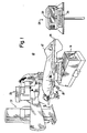
- Figure 1 illustrates in pictorial form a system 10 for acquiring digital Images by the use of x-rays.
- a patient 12 rests upon a table 14 which is movably supported on support structure 16, and which defines a patient examination station.
- An x-ray source 18 directs x-rays upwardly from beneath the table through the patient's body.
- An imaging unit 20 is aligned with the source to receive x-ray energy emergent from the patient's body.
- the imaging unit 20 is movably supported on articulated structure 22 to facilitate movement of the imaging unit 20 into alignment with a desired portion of the patient's body.
- An operating console 24 is electrically coupled to the imaging unit 20.
- the operating console 24 includes apparatus and circuitry for controlling the operation of some components of the system 10.
- the operating console 24 is coupled to a separate digital processing unit (DPU), shown in block form in Figure 2 as 23, whose function is described in more detail below, and to an imaging monitor 26.
- DPU digital processing unit
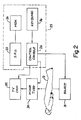
- Figure 2 is a simplified block diagram illustrating major components of the system 10.
- the source 18 in response to a command signal from the control console 24, produces a pulse of x-rays which pass through the body of the patient 12 and are incident on an input face of an image intensifier tube 30.
- the image intensifier tube 30, In response to the incident patern of x-rays, produces at an output face a visible light image corresponding to the pattern of received x-rays.
- the image intensifier tube 30 input face defines an area sufficiently large that, at least in some instances, when a human subject is being imaged, there will be an air region, i.e., a region over which radiation passes directly from the source to the image tube input face without first passing through the patient. Often, when radiation is high enough to effectively image the patient's body, the air region will exhibit saturation over a large area.
- the present invention has as one purpose the improvement in handling data corresponding to the air region portion of the image, in a manner described in more detail below.
- the visible light image produced by the image tube 30 is viewed by a television camera 32.
- the television camera 32 in response to command signals from the console 24, produces an ensemble of signals, including an analog video signal and horizontal and vertical synchronization signals, which describe in analog form the image viewd by the television camera 32.
- the analog signals are transmitted to a digital angiography subtraction unit (DAS) 25, which includes the control console 24, digital processing unit 23, monitor 26 and a keyboard 36 ( Figure 2).
- DAS digital angiography subtraction unit
- the digital angiography subtraction unit 25 digitizes the incoming analog signals. These digitized signals each represent the brightness of a particular respective corresponding portion, or pixel, of the image viewed by the television camera 32. Each of these digital brightness indicating signals is stored in a unique address in each of one or more digital memories. The address at which a particular signal is stored corresponds to the location of the pixel in the image whose brightness is represented by that stored signal.
- the digital angiography subtraction unit 25 also includes apparatus and circuitry means for processing the digitized information in known ways in order to enhance the image represented by the digital information. On command, the digital angiography subtraction unit 25 reconverts the stored and/or enhanced digital information to analog form, which is then applied to the monitor 26 to produce an analog image viewable by an operator.
- the operator communicates with and controls components of the system 10 by means of the keyboard 36.
- the system 10 as described above includes means for making both "study” images and for making “technique” images.
- the DAS 25 When instructed in one of a variety of particular ways, via the keyboard, the DAS 25 actuates the source to produce x-rays of a preselected level and duration.
- the DAS 25 is commanded to process the television signals thus acquired in accordance with a study protocol, which defines and corresponds to a particular desired anatomical study.
- the particular protocol differs from one type of anatomical study to another, in accordance with parameters which optimize the quality of the obtained image for displaying the particular desired anatomical organ or condition.
- the DAS can produce a "technique" or test image.
- the test image is obtained by actuating the source to produce a pulse of a particular level and duration, and by actuating the DAS to operate upon the received television signals in a particular way different from the manner in which the DAS operates upon the television signals in the course of a study image acquisition in accordance with one of the preselected study protocols.
- the system 10 comprises a vascular imaging system designated the "Digicon 260”, manufactured and sold by Picker International, Cleveland, Ohio, U.S.A. Also in the preferred embodiment, the system comprises a component designated the “DAS 211”, also sold by the above referenced Picker International.
- Digicon 260 and DAS 211 are both known systems, and are commercially available. Accordingly, the intimate details of these commercially available systems will not be discussed here. The remainder of this disclosure describes the manner of modifying the using those components to achieve the apparatus and method embodying the present invention.
- the present invention involves apparatus, circuitry and method for modifying test, or "technique" images acquired by the use of the system 10 in a manner which facilitates determination of whether the displayed image exhibits saturation, or near saturation.
- the stored digital information representing that image is altered, in accordance with a discontinuous gray scale mapping function.
- This modifying procedure comprises a gray scale mapping function having the following characteristics:
- the modified image When the modified image is viewed in an analog monitor, the image exhibits the following characteristics:
- the speckled, or near-saturation, region also helps to confirm to the operator that the adjacent black regions are really saturation-indicating artifacts, and are not actual images of dense tissue, such as bone or tumor.
- the practice of this invention enables the elimination of the judgment factor in ascertaining whether an image exhibits saturation, and where that saturation is located.
- the DAS 211 system digitizes the brightness of each incoming image pixel to ten bits, but can only store eight bits. Therefore, the DAS 211 is provided with a way to compress this brightness information. The way the DAS 211 does this is by means of a look-up table. With this, any digital incoming brightness can be transformed to another preselected brightness level. In prior art operation, this transformation was linear for "technique" images and therefore no real image processing of technique images was performed.
- linear look-up table is replaced by one which performs the gray scale transform functionally described above.
- This new look-up table is generally configured as follows;
- This acquisition map may be entered into the DAS 211 in one of two ways:
- any map can be specified as the one used in processing "technique" images.
- Figure 3 is a flow chart illustrating generally the procedure for preparing to do a study utilizing the system 10.
- the patient is prepared and properly positioned on the table.
- the x-ray source is caused to emit a pulse of x-rays, and a "technique" image is acquired in the manner generally decribed above.
- a decision is made whether the area of interest in the displayed technique shot is at least 50% of full scale brightness value. If the answer is No, box 46 indicates that the radiation level should be manually adjusted so that the area of interest is at aproximately 50% of full scale brightness value. Subsequent to such adjustment, another technique shot is performed.
- step 52 which constitutes the addition of x-ray absorber material under the saturated region of the technique image
- step 54 which is the repetition of another technique shot and a reevaluation of whether saturation Is present in that subsequent image.
- the system 10 is modified to provide for implementation of the present invention by manually inserting the new acquisition map into the DAS 25 by way of the keyboard associated with that component.
- the component to be modified comprises the above referenced DAS 211, which is commercially available in a preprogrammed state. The steps to be performed as called for below are implemented on the DAS 211 keyboard:
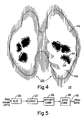
- Figure 4 illustrates a sample image obtained by the use of the present invention.
- the sample image 100 is depicted as an image of a human lung 102. Most of the image does not exhibit saturation, such as at the region 104, and that portion of the image not exhibiting saturation is displayed normally.
- a portion of the image at 106 exhibits saturation, and the saturation is indicated by the total black portion in the image.
- the region 108 surrounding the saturated region has a brightness value which is between 95% and 100% of saturation, and is depicted by a speckled pattern.
- Figure 4 also depicts an air region, generally indicated at 110.
- the air region 110 will be turned black. This eliminates the excessive brightness of the air region in the picture, and also reduces the amount of brightness information to be processed by the system, improving data rates. Also, if any form of gain correction is employed in the system, darkening the air region will eliminate the effect of any streaking which might otherwise result.
- Figure 5 is a block diagram illustating an implementation of saturation mapping circuit and method for imaging systems such as digital radiography systems employing detector assemblies having a plurality of individual discrete detector elements.
- Analog data from the detector array is fed to, and digitized by, an analog to digital converter 120.
- the digitized data then enters the saturation correction circuitry which comprises logic circuitry 122.
- the logic circuitry 122 comprises a circuit, which could be a simple look up table, easily designed by one of ordinary skill, to remap data passing through the logic circuitry to a zero value (black) when the digitized data corresponds to a pixel value of saturation, thus discarding the data. If the digitized data has not reached saturation, the logic circuitry transmits the data along in unmodified form.
- An offset correction circuit 126 subtracts the offset level of the particular detector element involved from the image pixel data value, clipping to zero all values which turn out to be negative after this offset subtraction operation is performed.
- Gain correction circuitry 128 multiples the image data value for the pixel , corresponding to the individual detector element assigned to that pixel, by a predetermined gain factor which is unique to the detector involved.
- Processed image data appears at an output lead 130.
- Figure 5 may exist in parallel for each discrete element of the detector assembly of the digital radiographic system, or the analog and/or digital data may be multiplexed to some degree, in which case there may be fewer circuit chains (such as in Figure 5) than there are detector elements.
- Figure 5 shows only one circuit chain, in the interest of simplicity.
- the invention is not limited to the particular scheme of artifact generation described in connection with this specific embodiment. More types of artifacts could be generated, in accordance with need.
- the method of generating artifacts can also be different than as described in this disclosure. For example, inasmuch as the saturated portions of the image exhibit a "flat" brightness profile, saturated areas could be located by gradient filtering techniques.
Description
- This invention relates to imaging, and more particularly is applicable to x-ray imaging employing digital image processing and display techniques.
- A known type of digital x-ray imaging system, directed particularly to vascular imaging, includes an x-ray source for directing x-rays through a patient to be examined, and an image intensifier tube aligned to receive a pattern of x-rays emergent from the patient's body. The image tube converts received x-rays to a corresponding visible light image. A television system views the light image and produces a set of analog signals describing that image. A digital angiography subtraction unit (DAS) receives the analog signals, and digitizes them, storing the signals in memory. The memory address of a particular stored signal denotes the portion, or "pixel" of the image which is represented by that signal. The stored digital signals each bear information defining the brightness of the image at the corresponding pixel.
- The digital angiography subtraction unit includes circuitry which, when programmed by appropriate known software, causes the digital angiography subtraction unit to process and enhance the digital signals in various known ways.
- The digital analog angiography subtraction unit also includes digital to analog conversion means for reconverting the stored and/or enhanced digital signals to analog form, for display on an appropriate analog monitor.
- An imaging system such as described above is embodied, for example, in a vascular imaging system designated the "DIGICON 260", manufactured and sold by Picker International, of Cleveland, Ohio, U.S.A. Other such systems include a DIGICON 160, and an ANGICON, also made and sold by Picker International. A known form of digital angiography subtraction unit is a product designated as "DAS 211", also sold by the above referenced Picker International.
- In operating such a digital vascular imaging system, before a series of diagnostic quality images can be acquired with the system, the user should acquire one or more test images as well. These test images are sometimes called "technique" images, and are often said to be acquired by means of a "technique shot".
- The technique images serve two purposes. They show whether the anatomy of interest is receiving a proper radiation exposure. Also, they show whether images to be taken later will have any "hot spots".
- "Hot spots" are those portions of the image that are so bright that the digital imaging system becomes saturated, and cannot handle them properly, because signals depicting those spots are greater than the dynamic range inherently defined as a limitation of the system.
- "Hot spots" occur mainly at areas of the anatomy which are air filled, such as the lungs, throat, etc. When radiation intensity is raised to a level high enough to penetrate, and therefore image, more dense portions of the body, such as the mediastinum, the resulting radiation is too intense in areas corresponding to air filled organs. Therefore, when the radiation is sufficiently high to image thick and dense portions of the anatomy, the radiation is too high to image the air filled regions properly. As pointed out above, the digital processing equipment has the inherent limitation that it cannot properly handle brightness information above a "saturation" level.
- If there are any saturated areas, some type of x-ray absorber element is often placed between the source and the patient in the area of the "hot spot" so that saturation is eliminated. After the absorber is put in place, another technique image must be acquired to see if saturation has been eliminated.
- Portions of absorber material having different shapes, thicknesses and compositions are kept available in "kits", to tailor the absorption characteristics to optimize the images.
- In the past, only very limited image processing has been performed on technique images. The unprocessed technique image was usually displayed to an operator, who had to judge whether saturation existed in any portion of the image. The operator generally tried to judge saturation by visual inspection of the image, i.e., by looking for loss of detail that usually accompanies such saturation.
- An aid to the operator has also been employed. In a known system, a set of six histogram plots corresponding to the brightness along six parallel spaced lines at different locations in the image is produced. An operator can couple information obtained from the histograms with visual inspection to ascertain whether saturation is present.
- A problem with this approach is that many operators have difficulty interpreting exactly what the histograms tell them. Also, the histograms only show information for the six image lines to which they correspond. Obviously, there are sizable gaps in the image with no corresponding histogram information. In these gaps, the operator must look for a very subtle loss of image detail to judge if there is saturation. Even experienced operators sometimes have trouble making this judgment.
- Additionally, the operators have difficulty relating hot spot location to the anatomy. They therefore have trouble deciding precisely where to apply the x-ray absorbers.
- The net effects of these problems are that operators of such vascular imaging systems spend considerable time performing technique shots, and, even with multiple technique acquisition, many actual digital study runs still have information loss due to areas of saturation.
- Disadvantages sometimes result where a portion of the field of view to be imaged includes a region outside the patient's body, i.e., a region in which radiation passes from the source to the detector, such as the image tube, in vascular imaging systems, without passing through a portion of the patient's body. Often, when the radiation is adjusted to a sufficiently high level to image the patient's body structures, the region or portion of the field of view outside the patient's body will be saturated. For purposes of the present disclosure, any portions of the field of view of the detector in which radiation passes directly to the detector without first passing through the patient's body will be called "air regions".
- Where these air regions generate saturation, they will appear in the image as intensely white, or bright. Some persons interpreting the images find this phenomenon to be distracting and to degrade the image. Also, processing information derived from air regions adds nothing to the information obtained about the patient's body, but still occupies a substantial portion of the information processing capability of the system.
- Other types of x-ray imaging systems such as digital radiographic systems employing detectors with discrete detector elements, rather than an image tube and television chain, also suffer disadvantages suffered by such digital radiography systems include some of those associated with the above described vascular imaging system, and some different disadvantages as well.
- In digital radiography, the source directs x-radiation through a patient's body to a detector in the beam path beyond the patient. The detector, by use of appropriate plural discrete sensor elements, responds to incident radiation to produce analog signals representing the sensed radiation image, which signals are converted to digital information and fed to a digital data processing unit. The data processing unit records, and/or processes and enhances the digital data. A display unit responds to the appropriate digital data representing the image to convert the digital information back into analog form and produce a visual display of the patient's internal body structure derived from the acquired image pattern of radiation emergent from the patient's body. The display system can be coupled directly to the digital data processing unit for substantially real time imaging, or can be fed stored digital data from digital storage means such as tapes or disks representing patient images from earlier studies.
- Digital radiography includes radiographic techniques in which a thin spread beam of x-rays is used. In this technique, often called "scan (or slit) projection radiography" (SPR) a spread beam of x-rays is directed through a patient's body. The spread beam is scanned across the patient, or the patient is movably interposed between the spread beam x-ray source and an array of individual cellular detector elements which are aligned along a path. Relative movement is effected between the source-detector arrangement and the patient's body, keeping the detector aligned with the beam, such that a large area of the patient's body is scanned by the spread beam of x-rays. Each of the detector segments produces analog signals indicating characteristics of the received x-rays.
- These analog signals are digitized and fed to the data processing unit which operates on the data in a preselected fashion to actuate the display apparatus to produce a display image representing the internal structure and/or condition of the patient's body.
- Details of digital radiographic systems are set forth in the following documents:
Lehman, L.A. et al: "Generalized Image Combinations in Dual KVP Digital Radiography", Medical Physics 8:659-667, 1981;
Published European Patent Specification No. EP-A-0115125;
United States Patent US.A-4,383,327 issued May 10, 1983 to Robert A.Kruger and entitled "Radiographic Systems Employing Multi-Linear Arrays of Electronic Radiation Detectors". - One of the advantages of digital radiography and fluoroscopy is that the digital image information generated from the emergent radiation pattern incident on the detector can be processed more easily than can analog data in various ways to enhance certain aspects of the image, to make the image more readily intelligible and to display a wider range of anatomical attenuation differences.
- While digital radiographic imaging procedures performed with cellular multi-element detectors do not usually include the taking of "technique" shots, the digital radiographic system suffers saturation-related disadvantages similar to those of the vascular systems, with respect to the extreme brightness of the air regions, and share the undesirability of requiring the system to process saturation-indicating data corresponding to air regions, which contributes nothing to the image of the patient's body.
- It is an object of the present invention to provide an imaging system and method which overcomes the above-described saturation-related disadvantages.
- According to one aspect of the present invention there is provided an imaging system including: means for propagating penetrative energy through an examination zone in which a body is located, detector means for detecting energy from said zone, means for producing electrical or optical signals corresponding to the detected energy, processing means for utilising said signals to produce an image corresponding to said zone, means for detecting the presence of first regions of said zone for which the brightness level of a reproduced image is at a saturation level, modifying means for introducing a first visual artifact in parts of the image corresponding to said first regions, and means for displaying said image characterised in that said system further includes means for detecting the presence of second regions of said zone for which the brightness level of a reproduced image exceeds a further predetermined level but is less than said saturation level and modifying means for introducing a second visual artifact in parts of the image corresponding to said second regions.
- Said further predetermined level is preferably 95% of saturation level.
- Suitably, said second visual artifact is an intermixed pattern of dark and light pixels and in a preferred embodiment, said first visual artifact is such that said first regions are displayed as a dark part of said image.
- According to a further aspect of the present invention, there is provided an imaging method including the steps of propagating penetrative energy from a source through an examination zone in which a body is located, detecting energy from said zone, producing electrical or optical signals corresponding to the detected energy, detecting the presence of first regions of said zone for which the brightness level of a reproduced image thereof exceeds a saturation level, introducing a first visual artifact in parts of the image corresponding to said first regions and displaying said image characterised in that said method further includes the steps of detecting the presence of second regions of said zone for which the brightness level of a reproduced image exceeds a further predetermined level but is less than said saturation level and introducing a second visual artifact in parts of the image corresponding to said second regions.
- Preferably the system includes the further steps of positioning radiation absorbing elements between said source and said regions, after displaying said image and the further steps of propagating penetrative energy through said zone, detecting energy therefrom, producing further electrical or optical signals corresponding to the energy detected in said further step and displaying a further image.
- The term "visual artifact," as used in this document, means any visible aspect of the image which does not correspond to the actual anatomical structure of the patient within the field of view defined by the image. Thus, a significant aspect of the invention resides in the deliberate introduction into a technique image of artifacts which correspond to and are used as indicators of ranges of relative brightness of various pixels of the image, with respect to full scale saturation value for the particular system being used.
- It can be seen that a system according to the invention greatly facilitates an operator's ready identification of saturated and near saturated portions of a technique image. Because the indications of saturation and near saturation are actually superposed on the image itself, this facilitates the operator's easy choice and location of any added absorber elements which are placed between the patient and the source to attenuate the radiation emergent from the patient's body in the portion of the field of view which corresponds to the saturated region.
- In the use of the present invention, all areas, or pixels, of each technique image are sampled for saturation, not merely the six lines sampled by the histograms of the prior art. Saturation is easily and unmistakably observed by visual inspection of the altered technique image, and no judgment is required in ascertaining whether saturation has occurred, or where it has occurred. Because the saturated areas are displayed in the patient image, rather than on a histogram, it is easy for an operator to relate the saturation location information shown in the altered technique image to actual areas of the patient's anatomy. This, of course, enables placement and selection of x-ray absorber elements, (e.g. material , shape, thickness, etc.) as needed, to be done with greater accuracy.
- The embodiment of the present invention is also advantageous in dealing with signals identifying brightness values for pixels within air regions, i.e., regions within the field of view in which radiation from the source strikes the detector without first passing through the patient's body. Where an air region is brightness saturated, the first artifact can be chosen such that the entire saturated air region will be turned to black. This has several important benefits. First, the excessively bright portion of the picture is eliminated and no longer provides distraction from the portion of the image depicting patient body structure. Secondly, where the system simply turns the air region black, there is no need to process any information corresponding to the air region itself. Signals can be simply discarded from the ensemble prior to image processing.
- Thirdly, where a digital radiography system is used employing a cellular multi-discrete element detector, turning the air regions black in response to saturation eliminates streaking of the saturated portion of the air region portion of the image which would sometimes otherwise result if image gain and/or offset correction techniques are used.
- FR-A-2073618 discloses an X-ray imaging system in which the brightness level of signals which exceeds a predetermined saturation level is reduced. This is done by inverting and amplifying that portion of the image signal which exceeds the saturation level and superimposing this inverted signal on the image signal.
- DE-A-3523514 describes a system in which signals with a brightness level above a predetermined level are shown as white regions on the displayed image.
- Neither of these systems provides a method of facilitating the recognition of areas in a reproduced image characterised by a saturated brightness.
- One imaging system and method in accordance with the invention will now be described, by way of example, with reference to the accompanying drawings in which:-
- Figure 1 is a pictorial view of a system incorporating the present invention;
- Figure 2 is a simplified block diagram depicting portions of the system of Figure 1;
- Figure 3 is a flow chart illustrating a method of operation of the system of Figures 1 and 2, and
- Figure 4 is an illustration of an image acquired by operation of the system of Figures 1 and 2 in accordance with the manner of operation depicted in Figure 3; and
- Figure 5 is a block diagram illustrating the manner of incorporation of an aspect of the present invention into a digital radiography system employing a cellular detector having multiple discrete elements.
- Figure 1 illustrates in pictorial form a
system 10 for acquiring digital Images by the use of x-rays. Apatient 12 rests upon a table 14 which is movably supported onsupport structure 16, and which defines a patient examination station. Anx-ray source 18 directs x-rays upwardly from beneath the table through the patient's body. Animaging unit 20 is aligned with the source to receive x-ray energy emergent from the patient's body. Theimaging unit 20 is movably supported on articulatedstructure 22 to facilitate movement of theimaging unit 20 into alignment with a desired portion of the patient's body. - An operating
console 24 is electrically coupled to theimaging unit 20. The operatingconsole 24 includes apparatus and circuitry for controlling the operation of some components of thesystem 10. The operatingconsole 24 is coupled to a separate digital processing unit (DPU), shown in block form in Figure 2 as 23, whose function is described in more detail below, and to animaging monitor 26. - Figure 2 is a simplified block diagram illustrating major components of the
system 10. In operation, thesource 18, in response to a command signal from thecontrol console 24, produces a pulse of x-rays which pass through the body of thepatient 12 and are incident on an input face of animage intensifier tube 30. Theimage intensifier tube 30, In response to the incident patern of x-rays, produces at an output face a visible light image corresponding to the pattern of received x-rays. - The
image intensifier tube 30 input face defines an area sufficiently large that, at least in some instances, when a human subject is being imaged, there will be an air region, i.e., a region over which radiation passes directly from the source to the image tube input face without first passing through the patient. Often, when radiation is high enough to effectively image the patient's body, the air region will exhibit saturation over a large area. The present invention has as one purpose the improvement in handling data corresponding to the air region portion of the image, in a manner described in more detail below. - The visible light image produced by the
image tube 30 is viewed by atelevision camera 32. Thetelevision camera 32, in response to command signals from theconsole 24, produces an ensemble of signals, including an analog video signal and horizontal and vertical synchronization signals, which describe in analog form the image viewd by thetelevision camera 32. - The analog signals are transmitted to a digital angiography subtraction unit (DAS) 25, which includes the
control console 24,digital processing unit 23, monitor 26 and a keyboard 36 (Figure 2). - The digital
angiography subtraction unit 25 digitizes the incoming analog signals. These digitized signals each represent the brightness of a particular respective corresponding portion, or pixel, of the image viewed by thetelevision camera 32. Each of these digital brightness indicating signals is stored in a unique address in each of one or more digital memories. The address at which a particular signal is stored corresponds to the location of the pixel in the image whose brightness is represented by that stored signal. - The digital
angiography subtraction unit 25 also includes apparatus and circuitry means for processing the digitized information in known ways in order to enhance the image represented by the digital information. On command, the digitalangiography subtraction unit 25 reconverts the stored and/or enhanced digital information to analog form, which is then applied to themonitor 26 to produce an analog image viewable by an operator. - The operator communicates with and controls components of the
system 10 by means of thekeyboard 36. - The
system 10 as described above includes means for making both "study" images and for making "technique" images. When instructed in one of a variety of particular ways, via the keyboard, theDAS 25 actuates the source to produce x-rays of a preselected level and duration. TheDAS 25 is commanded to process the television signals thus acquired in accordance with a study protocol, which defines and corresponds to a particular desired anatomical study. The particular protocol differs from one type of anatomical study to another, in accordance with parameters which optimize the quality of the obtained image for displaying the particular desired anatomical organ or condition. - When instructed differently, via the keyboard, the DAS, can produce a "technique" or test image. The test image is obtained by actuating the source to produce a pulse of a particular level and duration, and by actuating the DAS to operate upon the received television signals in a particular way different from the manner in which the DAS operates upon the television signals in the course of a study image acquisition in accordance with one of the preselected study protocols.
- In the preferred embodiment, the
system 10 comprises a vascular imaging system designated the "Digicon 260", manufactured and sold by Picker International, Cleveland, Ohio, U.S.A. Also in the preferred embodiment, the system comprises a component designated the "DAS 211", also sold by the above referenced Picker International. - The practice of this invention, however, it not limited to use in the preferred system. The invention can be applied to use in any type of digital imaging system.
- The Digicon 260 and DAS 211 are both known systems, and are commercially available. Accordingly, the intimate details of these commercially available systems will not be discussed here. The remainder of this disclosure describes the manner of modifying the using those components to achieve the apparatus and method embodying the present invention.
- Briefly, the present invention involves apparatus, circuitry and method for modifying test, or "technique" images acquired by the use of the
system 10 in a manner which facilitates determination of whether the displayed image exhibits saturation, or near saturation. - In acordance with the present invention, before the image from the "technique" shot is displayed, the stored digital information representing that image is altered, in accordance with a discontinuous gray scale mapping function. This modifying procedure comprises a gray scale mapping function having the following characteristics:
- 1. If the signal corresponding to the pixel being mapped denotes a brightness level below 95% of saturation, the brightness of that pixel is not changed;
- 2. If the signal corresponding to the pixel being mapped has a brightness of 100% of saturation, the brightness information of that signal is changed to that value denoting total black;
- 3. If the signal corresponding to the pixel being mapped denotes a brightness level in an intermediate range of between 95% and 100% of full scale saturation, the brightness information for that pixel is changed in accordance with an alternating dark and light gray scale mapping technique, as defined above, yielding usually an intermixed pattern of dark and light pixels.
- When the modified image is viewed in an analog monitor, the image exhibits the following characteristics:
- 1. In any area of the image wherein the brightness is of a value below 95% of full scale saturation value, the image appears normally;
- 2. For any area of saturation of the image, there occurs a black patch surrounded by intermixed dark and light pixels, and
- 3. In areas wherein the brightness level is below the full scale saturation value, but above 95% of full scale saturation value, there are dark and light pixels, but no solid black patches.
- These image characteristics render it easy for an operator to identify areas of the image at which saturation is occurring, and also areas at which the brightness is sufficiently close to saturation to warrant concern.
- The speckled, or near-saturation, region also helps to confirm to the operator that the adjacent black regions are really saturation-indicating artifacts, and are not actual images of dense tissue, such as bone or tumor.
- The practice of this invention enables the elimination of the judgment factor in ascertaining whether an image exhibits saturation, and where that saturation is located.
- This invention is practised utilising the above referenced Digicon 260 and DAS 211 equipment, with the aid of the following specific explanation and description.
- The DAS 211 system digitizes the brightness of each incoming image pixel to ten bits, but can only store eight bits. Therefore, the DAS 211 is provided with a way to compress this brightness information. The way the DAS 211 does this is by means of a look-up table. With this, any digital incoming brightness can be transformed to another preselected brightness level. In prior art operation, this transformation was linear for "technique" images and therefore no real image processing of technique images was performed.
- In the present invention, the linear look-up table is replaced by one which performs the gray scale transform functionally described above. This new look-up table is generally configured as follows;
- 1. If the input digital value is below 95% of full scale, the output is scaled linearly, as in the prior art;
- 2. For input values between 95% and 100% of full scale, the output values alternate between a linear value and zero, in accordance with an alternating dark and light gray scale mapping technique, and
- 3. For input values at 100% of full scale the output is zero. This creates the black patch at saturation.
- This acquisition map may be entered into the DAS 211 in one of two ways:
- 1. The DAS 211 allows an acquisition map to be entered point by point from the keyboard, and
- 2. The map can be copied in from storage.
- Once the map has been incorporated in the DAS 211 together with other maps, any map can be specified as the one used in processing "technique" images.
- Figure 3 is a flow chart illustrating generally the procedure for preparing to do a study utilizing the
system 10. - As stated at
box 40, the patient is prepared and properly positioned on the table. As indicated atbox 42, the x-ray source is caused to emit a pulse of x-rays, and a "technique" image is acquired in the manner generally decribed above. Indiamond 44, a decision is made whether the area of interest in the displayed technique shot is at least 50% of full scale brightness value. If the answer is No,box 46 indicates that the radiation level should be manually adjusted so that the area of interest is at aproximately 50% of full scale brightness value. Subsequent to such adjustment, another technique shot is performed. - If the area of interest is at approximately 50% of full scale value, another decision is made as indicated at
diamond 48, i.e. whether saturation is present in the technique image. If it is determined that no saturation is present, the process proceeds tobox 50 which indicates the desirability of proceeding with the actual study. - If saturation does appear in the technique image, the operator proceeds to the step indicated at
box 52, which constitutes the addition of x-ray absorber material under the saturated region of the technique image, followed by the step indicated in box 54 which is the repetition of another technique shot and a reevaluation of whether saturation Is present in that subsequent image. - In the preferred embodiment, the
system 10 is modified to provide for implementation of the present invention by manually inserting the new acquisition map into theDAS 25 by way of the keyboard associated with that component. As pointed out above, the component to be modified comprises the above referenced DAS 211, which is commercially available in a preprogrammed state. The steps to be performed as called for below are implemented on the DAS 211 keyboard: - 1. In the main DAS menu, choose 11 RUN OTHER PROGRAM
- 2. Run EXEC
- 3. At the prompt, type DIR FDO:ACMP.*
(This will list all the ACMP files.
Acquisition maps are stored in ACMP files and making a new map results in a new ACMP file. Write down the names of existing ACMP files so you can later identify the new one. The DAS already has 3 ACMP files: .AZZ, .A00 and .A01.) - 4. Return to main menu.
- 5. Choose 8 SYSTEM CHARACTERISTICS
- 6. Choose 4 ACQUISITION MAPS
- 7. Choose 3 CREATE AND STORE OTHER MAP
- 8. Choose 1 for KEYBOARD entry
- 9. Now enter the following data pairs
0,0
3888,243
3904,0
3920,245
3936,0
3952,247
3968,0
3984,249
4000,0
4016,251
4032,0
4048,253
4064,0
4080,255
4095,0 - 10. When the DAS asks for the map name, use BOLUS AID
- 11. Return to main menu.
- 12. In the main menu, choose 8 SYSTEM CHARACTERISTICS
- 13. Choose 5 SELECT SETUP DEFAULTS
- 14. Step through menu until "Acquisition Map for Technique" is reached
- 15. Choose BOLUS AID map
- 16. Return to main menu
- Figure 4 illustrates a sample image obtained by the use of the present invention. The
sample image 100 is depicted as an image of ahuman lung 102. Most of the image does not exhibit saturation, such as at theregion 104, and that portion of the image not exhibiting saturation is displayed normally. - A portion of the image at 106 exhibits saturation, and the saturation is indicated by the total black portion in the image. The
region 108 surrounding the saturated region has a brightness value which is between 95% and 100% of saturation, and is depicted by a speckled pattern. - Figure 4 also depicts an air region, generally indicated at 110. In instances in which the pixels constituting the
air region 110 have brightness signals associated therewith which exhibit saturation, theair region 110 will be turned black. This eliminates the excessive brightness of the air region in the picture, and also reduces the amount of brightness information to be processed by the system, improving data rates. Also, if any form of gain correction is employed in the system, darkening the air region will eliminate the effect of any streaking which might otherwise result. - Figure 5 is a block diagram illustating an implementation of saturation mapping circuit and method for imaging systems such as digital radiography systems employing detector assemblies having a plurality of individual discrete detector elements.
- Analog data from the detector array is fed to, and digitized by, an analog to
digital converter 120. The digitized data then enters the saturation correction circuitry which compriseslogic circuitry 122. Thelogic circuitry 122 comprises a circuit, which could be a simple look up table, easily designed by one of ordinary skill, to remap data passing through the logic circuitry to a zero value (black) when the digitized data corresponds to a pixel value of saturation, thus discarding the data. If the digitized data has not reached saturation, the logic circuitry transmits the data along in unmodified form. - An offset correction circuit 126 subtracts the offset level of the particular detector element involved from the image pixel data value, clipping to zero all values which turn out to be negative after this offset subtraction operation is performed.
-
Gain correction circuitry 128 multiples the image data value for the pixel , corresponding to the individual detector element assigned to that pixel, by a predetermined gain factor which is unique to the detector involved. - Processed image data appears at an
output lead 130. - It is significant to note that the elements shown in Figure 5 may exist in parallel for each discrete element of the detector assembly of the digital radiographic system, or the analog and/or digital data may be multiplexed to some degree, in which case there may be fewer circuit chains (such as in Figure 5) than there are detector elements. Figure 5 shows only one circuit chain, in the interest of simplicity.
- It should be pointed out that the implementation precisely described above is not the only way in which to implement the present invention. Rather, the present invention could also be implemented by the use of micro-processor circuitry of a fixed configuration, the design of which would be, with the aid of the present disclosure, within the ordinary level of skill in the art.
- It should also be noted that the invention is not limited to the particular scheme of artifact generation described in connection with this specific embodiment. More types of artifacts could be generated, in accordance with need. The method of generating artifacts can also be different than as described in this disclosure. For example, inasmuch as the saturated portions of the image exhibit a "flat" brightness profile, saturated areas could be located by gradient filtering techniques.
- It is also noted that this invention is by no means limited to the specific hardware systems described above. The present invention is readily extensible to use in any type of digital imaging, including digital radiography, ultrasonic imaging, NMR and others.
Claims (6)
- An imaging system (10) including: means (18) for propagating penetrative energy through an examination zone (14) in which a body (12) is located, detector means for detecting energy from said zone (14), means (20) for producing electrical or optical signals corresponding to the detected energy, processing means for utilising said signals to produce an image corresponding to said zone (14), means for detecting the presence of first regions of said zone (14) for which the brightness level of a reproduced image is at a predetermined saturation level, modifying means for introducing a first visual artifact in parts of the image (106, 110) corresponding to said first regions, and means (26) for displaying said image characterised in that said system further includes means for detecting the presence of second regions of said zone (14) for which the brightness level of a reproduced image exceeds a further predetermined level but is less than said saturation level and modifying means for introducing a second visual artifact in parts of the image (108) corresponding to said second regions.
- A system as claimed in Claim 1 wherein said further predetermined level is 95% of said saturation level.
- A system as claimed in Claim 1 or 2 wherein said second visual artifact is an intermixed pattern of dark and light pixels.
- A system as claimed in Claim 1, 2 or 3 wherein said first visual artifact is such that said first regions are displayed as a dark part of said image (106, 110).
- An imaging method including the steps of: propagating penetrative energy from a source (18) through an examination zone (14) in which a body (12) is located, detecting energy from said zone (14), producing electrical or optical signals corresponding to the detected energy, detecting the presence of first regions of said zone (14) for which the brightness level of a reproduced image thereof is at a saturation level, introducing a first visual artifact in parts of the image (106, 110) corresponding to said first regions and displaying said image characterised in that said method further includes the steps of detecting the presence of second regions of said zone (14) for which the brightness level of a reproduced image exceeds a further predetermined level but is less than said saturation level and introducing a second visual artifact in parts of the image (108) corresponding to said second regions.
- A method as claimed in Claim 5 including the steps of positioning radiation absorbing elements between said source (18) and said regions, after displaying said image and the further steps of propagating penetrative energy through said zone (14), detecting energy therefrom, producing further electrical or optical signals corresponding to the energy detected in said further step and displaying a further image.
Applications Claiming Priority (2)
| Application Number | Priority Date | Filing Date | Title |
|---|---|---|---|
| US852023 | 1986-04-14 | ||
| US06/852,023 US4891757A (en) | 1986-04-14 | 1986-04-14 | Medical imaging system and method having gray scale mapping means for indicating image saturation regions |
Publications (3)
| Publication Number | Publication Date |
|---|---|
| EP0244111A2 EP0244111A2 (en) | 1987-11-04 |
| EP0244111A3 EP0244111A3 (en) | 1989-02-08 |
| EP0244111B1 true EP0244111B1 (en) | 1992-07-22 |
Family
ID=25312321
Family Applications (1)
| Application Number | Title | Priority Date | Filing Date |
|---|---|---|---|
| EP87303137A Expired EP0244111B1 (en) | 1986-04-14 | 1987-04-10 | Imaging systems |
Country Status (4)
| Country | Link |
|---|---|
| US (1) | US4891757A (en) |
| EP (1) | EP0244111B1 (en) |
| JP (1) | JPS62246352A (en) |
| DE (1) | DE3780503T2 (en) |
Families Citing this family (16)
| Publication number | Priority date | Publication date | Assignee | Title |
|---|---|---|---|---|
| EP0445450A1 (en) * | 1990-03-07 | 1991-09-11 | International Business Machines Corporation | Image processor mepping source pixel intensities to a limited range of display intensity values |
| US5283736A (en) * | 1990-11-29 | 1994-02-01 | Konica Corporation | Radiographic image processing apparatus |
| JP3058680B2 (en) * | 1990-11-30 | 2000-07-04 | 株式会社トプコン | Fundus image processing device |
| US5119409A (en) * | 1990-12-28 | 1992-06-02 | Fischer Imaging Corporation | Dynamic pulse control for fluoroscopy |
| ES2150985T3 (en) * | 1993-02-26 | 2000-12-16 | E Y Lab Inc | PROCEDURE AND SYSTEM OF OPTICAL ANALYSIS OF SAMPLES. |
| EP0742536B1 (en) * | 1995-05-11 | 2000-09-13 | Agfa-Gevaert N.V. | Method of recognising one or more irradiation fields |
| US5815418A (en) * | 1996-01-31 | 1998-09-29 | Analogic Corporation | Continuous self-calibrating data acquistion system |
| NL1006420C2 (en) * | 1997-06-27 | 1998-12-29 | Optische Ind Oede Oude Delftoe | Method and device for displaying images. |
| US5978443A (en) * | 1997-11-10 | 1999-11-02 | General Electric Company | Automated removal of background regions from radiographic images |
| US6317510B1 (en) * | 1997-12-19 | 2001-11-13 | Fuji Photo Film Co., Ltd. | Blackening processing method and apparatus |
| JP2002502980A (en) * | 1998-02-10 | 2002-01-29 | イーワイ ラボラトリーズ インコーポレイテッド | Reflection measurement system that compensates for sample holder undulations and removes system noise lock |
| US6460003B1 (en) | 1999-07-01 | 2002-10-01 | General Electric Company | Apparatus and method for resolution calibration of radiographic images |
| FR2796740B1 (en) * | 1999-07-19 | 2001-10-26 | Ge Medical Syst Sa | METHOD AND SYSTEM FOR MANAGING THE SATURATION ON A DIGITIZED RADIOGRAPHIC IMAGE |
| US6987872B2 (en) * | 2001-06-28 | 2006-01-17 | General Electric Company | Method and system of contrast management of images using SIMD instructions and saturation arithmetic |
| US7606347B2 (en) * | 2004-09-13 | 2009-10-20 | General Electric Company | Photon counting x-ray detector with overrange logic control |
| US8111904B2 (en) * | 2005-10-07 | 2012-02-07 | Cognex Technology And Investment Corp. | Methods and apparatus for practical 3D vision system |
Family Cites Families (8)
| Publication number | Priority date | Publication date | Assignee | Title |
|---|---|---|---|---|
| US32164A (en) * | 1861-04-23 | Stove | ||
| DE1962330A1 (en) * | 1969-12-12 | 1971-06-24 | Siemens Ag | X-ray diagnostic device with an image amplifier television chain |
| US4229764A (en) * | 1978-07-03 | 1980-10-21 | Michael Danos | Visibility expander |
| US4257063A (en) * | 1979-03-23 | 1981-03-17 | Ham Industries, Inc. | Video monitoring system and method |
| USRE32164E (en) | 1980-12-01 | 1986-05-27 | The University Of Utah | Radiographic systems employing multi-linear arrays of electronic radiation detectors |
| JPS59118135A (en) * | 1982-12-27 | 1984-07-07 | 株式会社東芝 | X-ray photographing apparatus |
| IL69326A (en) * | 1983-07-26 | 1986-11-30 | Elscint Ltd | System and methods for translating radiation intensity into pixel values |
| JPS6116371A (en) * | 1984-07-03 | 1986-01-24 | Toshiba Corp | Digital fluorography device |
-
1986
- 1986-04-14 US US06/852,023 patent/US4891757A/en not_active Expired - Fee Related
-
1987
- 1987-04-10 DE DE8787303137T patent/DE3780503T2/en not_active Expired - Fee Related
- 1987-04-10 EP EP87303137A patent/EP0244111B1/en not_active Expired
- 1987-04-13 JP JP62090615A patent/JPS62246352A/en active Pending
Also Published As
| Publication number | Publication date |
|---|---|
| DE3780503T2 (en) | 1993-01-21 |
| JPS62246352A (en) | 1987-10-27 |
| EP0244111A2 (en) | 1987-11-04 |
| DE3780503D1 (en) | 1992-08-27 |
| EP0244111A3 (en) | 1989-02-08 |
| US4891757A (en) | 1990-01-02 |
Similar Documents
| Publication | Publication Date | Title |
|---|---|---|
| US4736399A (en) | X-ray imaging apparatus | |
| EP0244111B1 (en) | Imaging systems | |
| US5852646A (en) | X-ray imaging method | |
| CN101632591B (en) | Radiograph and image processing program | |
| DE2815218C2 (en) | ||
| EP0963549B1 (en) | Bone densitometry using x-ray imaging systems | |
| JPH10509075A (en) | Bone densitometer with improved indicating characteristics | |
| DE3814246A1 (en) | MEDICAL EXAMINATION SYSTEM WITH AN IMAGING DEVICE | |
| JPH0412969B2 (en) | ||
| JP2003180667A (en) | Method and device for intensifying the contrast of a medical diagnostic image acquired using collimation | |
| EP0066824B1 (en) | X-ray image digital substraction system | |
| EP0223544A2 (en) | Substance quantification in animal bodies | |
| US5978443A (en) | Automated removal of background regions from radiographic images | |
| DE60317411T2 (en) | Method and system for reducing the radiation load | |
| US4562464A (en) | X-Ray diagnostic apparatus | |
| JPH11299765A (en) | X-ray device | |
| EP1253557A1 (en) | Apparatus for and method of generating an enhanced contrast information digital image | |
| US5923724A (en) | Medical x-ray diagnostic installation and method for operating same | |
| US5761333A (en) | Contrast enhancement for CT systems | |
| JPH05161633A (en) | Radiation diagnostic device | |
| DE102006048233A1 (en) | X-ray arrangement for patient examination, has computing unit with converter having input device for complete data set of simply adjustable system parameters that are fed by user for convert into complete data set of image chain parameters | |
| JPH08146540A (en) | Image processing device and image data originating device | |
| DE60036355T2 (en) | Method and device for optimizing the image quality of the computer tomograph with optimal data acquisition | |
| US4479231A (en) | Method for the production of X-ray images and X-ray television apparatus for carrying out said method | |
| JP3641499B2 (en) | Digital X-ray device |
Legal Events
| Date | Code | Title | Description |
|---|---|---|---|
| PUAI | Public reference made under article 153(3) epc to a published international application that has entered the european phase |
Free format text: ORIGINAL CODE: 0009012 |
|
| AK | Designated contracting states |
Kind code of ref document: A2 Designated state(s): DE GB |
|
| PUAL | Search report despatched |
Free format text: ORIGINAL CODE: 0009013 |
|
| AK | Designated contracting states |
Kind code of ref document: A3 Designated state(s): DE GB |
|
| 17P | Request for examination filed |
Effective date: 19890515 |
|
| 17Q | First examination report despatched |
Effective date: 19910617 |
|
| GRAA | (expected) grant |
Free format text: ORIGINAL CODE: 0009210 |
|
| STAA | Information on the status of an ep patent application or granted ep patent |
Free format text: STATUS: THE PATENT HAS BEEN GRANTED |
|
| AK | Designated contracting states |
Kind code of ref document: B1 Designated state(s): DE GB |
|
| REF | Corresponds to: |
Ref document number: 3780503 Country of ref document: DE Date of ref document: 19920827 |
|
| PGFP | Annual fee paid to national office [announced via postgrant information from national office to epo] |
Ref country code: GB Payment date: 19930317 Year of fee payment: 7 |
|
| PLBE | No opposition filed within time limit |
Free format text: ORIGINAL CODE: 0009261 |
|
| PGFP | Annual fee paid to national office [announced via postgrant information from national office to epo] |
Ref country code: DE Payment date: 19930626 Year of fee payment: 7 |
|
| 26N | No opposition filed | ||
| PG25 | Lapsed in a contracting state [announced via postgrant information from national office to epo] |
Ref country code: GB Effective date: 19940410 |
|
| GBPC | Gb: european patent ceased through non-payment of renewal fee |
Effective date: 19940410 |
|
| PG25 | Lapsed in a contracting state [announced via postgrant information from national office to epo] |
Ref country code: DE Effective date: 19950103 |