EP0244045A1 - Sensoranordnung für einen Wirbelströmungsmesser - Google Patents
Sensoranordnung für einen Wirbelströmungsmesser Download PDFInfo
- Publication number
- EP0244045A1 EP0244045A1 EP87300383A EP87300383A EP0244045A1 EP 0244045 A1 EP0244045 A1 EP 0244045A1 EP 87300383 A EP87300383 A EP 87300383A EP 87300383 A EP87300383 A EP 87300383A EP 0244045 A1 EP0244045 A1 EP 0244045A1
- Authority
- EP
- European Patent Office
- Prior art keywords
- sensor
- mounting bracket
- housing
- space
- jaw
- Prior art date
- Legal status (The legal status is an assumption and is not a legal conclusion. Google has not performed a legal analysis and makes no representation as to the accuracy of the status listed.)
- Granted
Links
- 239000012530 fluid Substances 0.000 claims abstract description 21
- 239000013307 optical fiber Substances 0.000 claims description 4
- 230000001419 dependent effect Effects 0.000 claims 1
- 239000000835 fiber Substances 0.000 description 9
- 238000000034 method Methods 0.000 description 2
- 230000004888 barrier function Effects 0.000 description 1
- 230000008878 coupling Effects 0.000 description 1
- 238000010168 coupling process Methods 0.000 description 1
- 238000005859 coupling reaction Methods 0.000 description 1
- 230000002950 deficient Effects 0.000 description 1
- 238000004519 manufacturing process Methods 0.000 description 1
- 230000003287 optical effect Effects 0.000 description 1
- 235000020004 porter Nutrition 0.000 description 1
- 238000003466 welding Methods 0.000 description 1
Images
Classifications
-
- G—PHYSICS
- G01—MEASURING; TESTING
- G01F—MEASURING VOLUME, VOLUME FLOW, MASS FLOW OR LIQUID LEVEL; METERING BY VOLUME
- G01F1/00—Measuring the volume flow or mass flow of fluid or fluent solid material wherein the fluid passes through a meter in a continuous flow
- G01F1/05—Measuring the volume flow or mass flow of fluid or fluent solid material wherein the fluid passes through a meter in a continuous flow by using mechanical effects
- G01F1/20—Measuring the volume flow or mass flow of fluid or fluent solid material wherein the fluid passes through a meter in a continuous flow by using mechanical effects by detection of dynamic effects of the flow
- G01F1/32—Measuring the volume flow or mass flow of fluid or fluent solid material wherein the fluid passes through a meter in a continuous flow by using mechanical effects by detection of dynamic effects of the flow using swirl flowmeters
-
- G—PHYSICS
- G01—MEASURING; TESTING
- G01F—MEASURING VOLUME, VOLUME FLOW, MASS FLOW OR LIQUID LEVEL; METERING BY VOLUME
- G01F15/00—Details of, or accessories for, apparatus of groups G01F1/00 - G01F13/00 insofar as such details or appliances are not adapted to particular types of such apparatus
- G01F15/18—Supports or connecting means for meters
- G01F15/185—Connecting means, e.g. bypass conduits
-
- G—PHYSICS
- G01—MEASURING; TESTING
- G01F—MEASURING VOLUME, VOLUME FLOW, MASS FLOW OR LIQUID LEVEL; METERING BY VOLUME
- G01F1/00—Measuring the volume flow or mass flow of fluid or fluent solid material wherein the fluid passes through a meter in a continuous flow
- G01F1/05—Measuring the volume flow or mass flow of fluid or fluent solid material wherein the fluid passes through a meter in a continuous flow by using mechanical effects
- G01F1/20—Measuring the volume flow or mass flow of fluid or fluent solid material wherein the fluid passes through a meter in a continuous flow by using mechanical effects by detection of dynamic effects of the flow
- G01F1/32—Measuring the volume flow or mass flow of fluid or fluent solid material wherein the fluid passes through a meter in a continuous flow by using mechanical effects by detection of dynamic effects of the flow using swirl flowmeters
- G01F1/3209—Measuring the volume flow or mass flow of fluid or fluent solid material wherein the fluid passes through a meter in a continuous flow by using mechanical effects by detection of dynamic effects of the flow using swirl flowmeters using Karman vortices
Definitions
- This invention relates to a sensor arrangement for a vortex shedding flowmeter.
- Patent specification US-A-4 519 259 discloses a vortex shedding flowmeter which utilizes a light barrier to sense the passage of a vortex.
- a sensor arrangement for a vortex shedding flowmeter characterised by: a sensor housing defining a sensor space; a sensor beam having an upper portion extending into the sensor space and a lower portion extending from the sensor housing into a fluid flow space outside the sensor housing; pressure boundary means connected to the lower portion of the sensor beam for isolating the sensor space from the fluid space; a mounting bracket detachably connected to the sensor housing; and a sensor assembly disposed in the sensor space connected to the mounting bracket and operatively engaged with the upper portion of the sensor beam for sensing movement of the sensor beam caused by vortices passing the lower portion of the sensor beam disposed in the fluid flow space, wherein the sensor assembly is removable with the mounting bracket from the sensor housing without disturbing the pressure boundary maintained by the pressure boundary means.
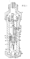
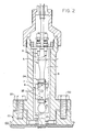
- a vortex shedding flowmeter has a flowmeter housing 22 which is exposed in use to a flowing fluid in a fluid flow space 100 which is below the flowmeter housing 22 shown in the Figures.
- a substantially cylindrical sensor housing 9 is connected to the flowmeter housing 22 by bolts 30 and defines an inner sensor space.
- a sensor beam 10 has an upper portion 10 a which extends within the sensor space, and a lower portion 10 b which extends through the flow meter housing 22 into the fluid flow space 100.
- a pressure boundary means for example in the form of a flexible diaphragm 23, is connected between the sensor housing 9 and the flowmeter housing 22, to isolate the sensor space in the housing 9 from the fluid flow space 100 on another side of the flowmeter housing 22.
- the diaphragm 23 thus forms a pressure boundary 21 which, need not be disturbed even when a sensing element in the sensor housing 9 is replaced.
- a sensor assembly 24 is detachably mounted in the sensor space of the sensor housing 9. It comprises a mounting bracket 1 which has an upper flange portion 1 a that can be detachably fixed to the sensor housing 9.
- the sensor housing 9 includes an upper step which has a downwardly extending blind bore into which a pin 19 extends.
- the pin 19 is connected to the flange portion 1 a and is used to establish a correct rotational position of the bracket 1 in the sensor housing 9.
- the upper flange portion 1 a is detachably fixed to the sensor housing 9 by a lock nut 18 which is threaded into the upper end of the sensor housing 9.
- a cover 31 is threaded over the upper end of the sensor housing 9 to cover the sensor space.
- the mounting bracket 1 forms a frame or fixture for holding the sensor assembly 24.
- the sensor assembly 24 includes a first microbend jaw 2 which is attached to the mounting bracket 1 by means of a spring 4.
- a second microbend jaw 3 is held to the jaw 2 with a fibre optic cable 5 located between the first and second jaws 2 and 3.
- the fibre optic cable 5 is in the form of a loop which terminates in connectors 6 which are attached to the flange portion 1 a of the mounting bracket 1.
- the connectors 6 are used for coupling a light signal to circuitry (not shown) for analyzing light passing through the fibre optic cable 5.
- the fibre optic cable 5 is supported and positioned by a supporting tab 7 connected to the mounting bracket 1. This supporting tab 7 is located between the bottom of the connector 6 and the top of the jaws 2, 3.
- the fibre optic cable 5 is also held and positioned correctly in the jaw 2 by means of clamps 8. All of these components comprise an integral and independent subassembly unit which is placed in the sensor housing 9. The jaws 2, 3 are aligned to each other by means of slip pins 25.
- the jaw 3 has a mounting tab 11 with a hole 12 therein to receive a mounting screw 13. In this way the jaw 3 is held fast to the upper portion 10 a of the sensor beam 10.
- the jaw 3 also has a lip 14 which extends into a groove 15 of the sensor beam 10.
- a threaded hole 16 in the sensor beam 10 threadably receives the mounting screw 13.
- the jaw 3 When assembled, the jaw 3 is rigidly held with respect to the sensor beam 10 which serves as a mechanical input to the sensor assembly 24.
- the sensor beam 10 When vortices in the fluid space 100 pass the lower portion 10 b of the sensor beam 10, the sensor beam 10 is caused to pivot about the diaphragm 23. This pivotal movement is transferred to the jaw 3 which, in co-operation with the jaw 2, squeezes and releases the fibre optic cable 5. This modulates light passing through the fibre optic cable 5. The modulations can be detected and correspond to the passage of the vortices.
- An access hole 20 is provided in the flange portion 1 a of the mounting bracket 1 to provide access to the mounting screw 13 for disconnecting the mounting tab 11 from the sensor beam 10.
- a hole 17 in the mounting bracket 1 is sized larger than the jaw 2 and receives the jaw 2. The hole 17, in conjunction with the spring 4, provides the necessary degree of freedom for self-alignment of the jaws 2, 3 with respect to the upper portion 10 a of the sensor beam 10.
- An adjustment screw 32 is threaded into the sensor housing 9 and permits adjustment of the position of a calibration arm 34 so that it bears down on the jaw 2 and provides an initial adjustment for the sensor assembly 24.
- the sensor assembly 24 becomes defective, it can easily be replaced by the following steps. First the cover 31 is removed and the mounting screw 13 which is accessed through the access hole 20 is unscrewed. This frees the jaw 3, and thus the whole sensor assembly 24, from the sensor beam 10. The lock nut 18 is then removed freeing the mounting bracket 1. The mounting bracket 1 is then removed along with the connectors 6, the jaws 2, 3 and all other parts connected to the bracket 1. A new sensor assembly 24 can then be inserted into the sensor housing 9. It is noted that this replacement operation does not disturb the pressure boundary 21 nor the lower portion 10 b of the sensor beam 10.
- optical fibre sensor is used in the illustrated embodiment, other types of sensor elements can be used such as optical reflective type sensors, electromagnetic pick-up sensors and strain gauge sensors. For some sensor elements it might not even be necessary to establish connection or contact between the sensing element and the sensor beam 10.
Landscapes
- Physics & Mathematics (AREA)
- Fluid Mechanics (AREA)
- General Physics & Mathematics (AREA)
- Measuring Volume Flow (AREA)
- Measuring Fluid Pressure (AREA)
Applications Claiming Priority (2)
| Application Number | Priority Date | Filing Date | Title |
|---|---|---|---|
| US06/825,413 US4679445A (en) | 1986-02-03 | 1986-02-03 | On-line replacement sensor assembly for a vortex shedding flowmeter |
| US825413 | 1986-02-03 |
Publications (2)
| Publication Number | Publication Date |
|---|---|
| EP0244045A1 true EP0244045A1 (de) | 1987-11-04 |
| EP0244045B1 EP0244045B1 (de) | 1991-07-10 |
Family
ID=25243963
Family Applications (1)
| Application Number | Title | Priority Date | Filing Date |
|---|---|---|---|
| EP87300383A Expired - Lifetime EP0244045B1 (de) | 1986-02-03 | 1987-01-16 | Sensoranordnung für einen Wirbelströmungsmesser |
Country Status (13)
| Country | Link |
|---|---|
| US (1) | US4679445A (de) |
| EP (1) | EP0244045B1 (de) |
| JP (1) | JPS62203018A (de) |
| KR (1) | KR940000139B1 (de) |
| AU (1) | AU586035B2 (de) |
| BR (1) | BR8700450A (de) |
| CA (1) | CA1280912C (de) |
| DE (1) | DE3771268D1 (de) |
| ES (1) | ES2002455A6 (de) |
| HK (1) | HK103291A (de) |
| IN (1) | IN165909B (de) |
| MX (1) | MX168786B (de) |
| SG (1) | SG87791G (de) |
Cited By (2)
| Publication number | Priority date | Publication date | Assignee | Title |
|---|---|---|---|---|
| GB2326720A (en) * | 1997-06-25 | 1998-12-30 | Ford Motor Co | Method of preventing odometer fraud |
| CN105784033A (zh) * | 2016-05-05 | 2016-07-20 | 汇中仪表股份有限公司 | 一种薄片型多声路超声测流传感器及其使用方法 |
Families Citing this family (8)
| Publication number | Priority date | Publication date | Assignee | Title |
|---|---|---|---|---|
| US4926695A (en) * | 1987-09-15 | 1990-05-22 | Rosemount Inc. | Rocking beam vortex sensor |
| US5313843A (en) * | 1990-01-29 | 1994-05-24 | Fuji Electric Co., Ltd. | Karman vortex flow meter |
| US5197336A (en) * | 1990-01-29 | 1993-03-30 | Fuji Electric Co., Ltd. | Karman vortex flow meter |
| US5220842A (en) * | 1990-12-31 | 1993-06-22 | Lew Hyok S | Vortex generator-sensor with pivotally balanced mass distribution |
| US5343762A (en) * | 1992-10-05 | 1994-09-06 | Rosemount Inc. | Vortex flowmeter |
| US5498861A (en) * | 1992-10-08 | 1996-03-12 | Square D Company | Sensing head for code reading having multiple replaceable sensors |
| EP1936332A1 (de) * | 2006-12-22 | 2008-06-25 | Nederlandse Organisatie voor Toegepast-Natuuurwetenschappelijk Onderzoek TNO | Karman-Vortex Durchflussmesser mit faseroptischem Bragg-Sensor sowie Verfahren zur Messung einer Durchflussrate |
| WO2011078722A1 (en) | 2009-12-24 | 2011-06-30 | Rosemount Inc. | Vortex flow meter with vortex oscillation sensor plate supported by struts |
Citations (4)
| Publication number | Priority date | Publication date | Assignee | Title |
|---|---|---|---|---|
| US4094194A (en) * | 1977-02-14 | 1978-06-13 | Fischer & Porter Company | Sensing system for vortex-type flowmeters |
| GB2093999A (en) * | 1981-02-20 | 1982-09-08 | Foxboro Co | External sensing vortex flowmeter |
| US4463254A (en) * | 1981-08-27 | 1984-07-31 | Trw Inc. | Microbending of optical fibers for remote force measurement |
| US4552026A (en) * | 1984-10-22 | 1985-11-12 | The Babcock & Wilcox Company | Sensor for a vortex shedding flowmeter |
Family Cites Families (10)
| Publication number | Priority date | Publication date | Assignee | Title |
|---|---|---|---|---|
| BE394587A (de) * | 1932-02-25 | |||
| US4033189A (en) * | 1976-03-26 | 1977-07-05 | Fischer & Porter Co. | External-sensor vortex-type flowmeter |
| US4291583A (en) * | 1979-10-01 | 1981-09-29 | The Bendix Corporation | Drag flow meter |
| JPS56149915U (de) * | 1980-04-11 | 1981-11-11 | ||
| JPS5849217U (ja) * | 1981-09-30 | 1983-04-02 | オ−バル機器工業株式会社 | 渦流量計 |
| JPS58160813A (ja) * | 1982-03-17 | 1983-09-24 | Yokogawa Hokushin Electric Corp | 渦流量計 |
| JPS5915919U (ja) * | 1982-07-23 | 1984-01-31 | オ−バル機器工業株式会社 | 渦流量計 |
| JPS5945521U (ja) * | 1982-09-20 | 1984-03-26 | トキコ株式会社 | 流速流量検出装置 |
| GB2131171A (en) * | 1982-11-25 | 1984-06-13 | Normalair Garrett | Vorten flowmeter using optical differential pressure sensor |
| JPS59142727A (ja) * | 1983-02-01 | 1984-08-16 | Seiko Epson Corp | Vtrヘツド用シリンダ−ユニツト |
-
1986
- 1986-02-03 US US06/825,413 patent/US4679445A/en not_active Expired - Fee Related
- 1986-09-17 IN IN687/CAL/86A patent/IN165909B/en unknown
- 1986-09-25 AU AU63179/86A patent/AU586035B2/en not_active Ceased
- 1986-10-06 KR KR1019860008351A patent/KR940000139B1/ko not_active Expired - Lifetime
-
1987
- 1987-01-14 MX MX004934A patent/MX168786B/es unknown
- 1987-01-16 DE DE8787300383T patent/DE3771268D1/de not_active Expired - Fee Related
- 1987-01-16 ES ES8700101A patent/ES2002455A6/es not_active Expired - Fee Related
- 1987-01-16 EP EP87300383A patent/EP0244045B1/de not_active Expired - Lifetime
- 1987-01-29 JP JP62017445A patent/JPS62203018A/ja active Granted
- 1987-01-30 BR BR8700450A patent/BR8700450A/pt unknown
- 1987-02-02 CA CA000528783A patent/CA1280912C/en not_active Expired - Fee Related
-
1991
- 1991-10-21 SG SG877/91A patent/SG87791G/en unknown
- 1991-12-19 HK HK1032/91A patent/HK103291A/xx unknown
Patent Citations (4)
| Publication number | Priority date | Publication date | Assignee | Title |
|---|---|---|---|---|
| US4094194A (en) * | 1977-02-14 | 1978-06-13 | Fischer & Porter Company | Sensing system for vortex-type flowmeters |
| GB2093999A (en) * | 1981-02-20 | 1982-09-08 | Foxboro Co | External sensing vortex flowmeter |
| US4463254A (en) * | 1981-08-27 | 1984-07-31 | Trw Inc. | Microbending of optical fibers for remote force measurement |
| US4552026A (en) * | 1984-10-22 | 1985-11-12 | The Babcock & Wilcox Company | Sensor for a vortex shedding flowmeter |
Cited By (4)
| Publication number | Priority date | Publication date | Assignee | Title |
|---|---|---|---|---|
| GB2326720A (en) * | 1997-06-25 | 1998-12-30 | Ford Motor Co | Method of preventing odometer fraud |
| GB2326720B (en) * | 1997-06-25 | 2001-08-15 | Ford Motor Co | Method of preventing odometer fraud |
| CN105784033A (zh) * | 2016-05-05 | 2016-07-20 | 汇中仪表股份有限公司 | 一种薄片型多声路超声测流传感器及其使用方法 |
| CN105784033B (zh) * | 2016-05-05 | 2022-02-01 | 汇中仪表股份有限公司 | 一种薄片型多声路超声测流传感器及其使用方法 |
Also Published As
| Publication number | Publication date |
|---|---|
| DE3771268D1 (de) | 1991-08-14 |
| MX168786B (es) | 1993-06-08 |
| US4679445A (en) | 1987-07-14 |
| KR870008172A (ko) | 1987-09-24 |
| KR940000139B1 (ko) | 1994-01-07 |
| JPH0569363B2 (de) | 1993-09-30 |
| AU6317986A (en) | 1987-08-06 |
| EP0244045B1 (de) | 1991-07-10 |
| AU586035B2 (en) | 1989-06-29 |
| CA1280912C (en) | 1991-03-05 |
| SG87791G (en) | 1991-11-22 |
| IN165909B (de) | 1990-02-10 |
| ES2002455A6 (es) | 1991-11-01 |
| JPS62203018A (ja) | 1987-09-07 |
| BR8700450A (pt) | 1987-12-08 |
| HK103291A (en) | 1991-12-27 |
Similar Documents
| Publication | Publication Date | Title |
|---|---|---|
| EP0103010B1 (de) | Wirbelstrom-differenzdruck-durchflussmesser | |
| EP0244045A1 (de) | Sensoranordnung für einen Wirbelströmungsmesser | |
| AU616499B2 (en) | Rocking beam vortex sensor | |
| US6957588B1 (en) | Fluid measuring device and method | |
| US5531120A (en) | Compact differential pressure transmitter having first and second damper chambers | |
| US4088020A (en) | Vortex flowmeter apparatus | |
| AU571825B2 (en) | Reference pressure devices for calibrating pressure-measuringinstruments | |
| GB2265465A (en) | Differential pressure transducer assembly | |
| US6971272B2 (en) | Integrated fluid sensing device | |
| US4718279A (en) | Dual bourdon tube type sensing pressure transducer | |
| EP0417058A1 (de) | Kraftübertragende Vorrichtung für einen Wirbel-Durchflussmesser | |
| EP0721108B1 (de) | Messwertaufnehmer für Beschleunigungszustand | |
| US4380935A (en) | External sensing vortex flowmeter | |
| WO1998038477A1 (en) | Serviceable measuring device | |
| EP0240100A1 (de) | Backenanordnung für einen Mikrobiegesensor | |
| JP7664604B2 (ja) | 圧力検出装置 | |
| EP0197043B1 (de) | Verfahren und vorrichtung zur eichung des messbereichs von druckmesseinrichtungen | |
| US6895130B1 (en) | True position sensor for diaphragm valves using reflected light property variation | |
| JPS5827855B2 (ja) | パイプラインチユウノピツグオタンチスルピツグタンチキオチヨウセイスルホウホウ オヨビ ソウチ | |
| WO2025007976A1 (zh) | 压力传感器 | |
| EP0304269B1 (de) | Strömungsmessgerät | |
| JPH0343499Y2 (de) | ||
| US20250216280A1 (en) | Pressure measuring module for a pneumatic device of a vehicle | |
| GB2349700A (en) | Flowmeter with diaphragm and strain gauges | |
| GB2169414A (en) | Density measuring apparatus with electrical display |
Legal Events
| Date | Code | Title | Description |
|---|---|---|---|
| PUAI | Public reference made under article 153(3) epc to a published international application that has entered the european phase |
Free format text: ORIGINAL CODE: 0009012 |
|
| AK | Designated contracting states |
Kind code of ref document: A1 Designated state(s): DE FR GB IT SE |
|
| 17P | Request for examination filed |
Effective date: 19880415 |
|
| 17Q | First examination report despatched |
Effective date: 19891110 |
|
| RAP1 | Party data changed (applicant data changed or rights of an application transferred) |
Owner name: INTERNATIONAL CONTROL AUTOMATION FINANCE S.A. |
|
| GRAA | (expected) grant |
Free format text: ORIGINAL CODE: 0009210 |
|
| AK | Designated contracting states |
Kind code of ref document: B1 Designated state(s): DE FR GB IT SE |
|
| ITF | It: translation for a ep patent filed | ||
| REF | Corresponds to: |
Ref document number: 3771268 Country of ref document: DE Date of ref document: 19910814 |
|
| ET | Fr: translation filed | ||
| PLBE | No opposition filed within time limit |
Free format text: ORIGINAL CODE: 0009261 |
|
| STAA | Information on the status of an ep patent application or granted ep patent |
Free format text: STATUS: NO OPPOSITION FILED WITHIN TIME LIMIT |
|
| 26N | No opposition filed | ||
| PGFP | Annual fee paid to national office [announced via postgrant information from national office to epo] |
Ref country code: FR Payment date: 19921210 Year of fee payment: 7 |
|
| PGFP | Annual fee paid to national office [announced via postgrant information from national office to epo] |
Ref country code: SE Payment date: 19921211 Year of fee payment: 7 Ref country code: DE Payment date: 19921211 Year of fee payment: 7 |
|
| PGFP | Annual fee paid to national office [announced via postgrant information from national office to epo] |
Ref country code: GB Payment date: 19921231 Year of fee payment: 7 |
|
| PG25 | Lapsed in a contracting state [announced via postgrant information from national office to epo] |
Ref country code: GB Effective date: 19940116 |
|
| PG25 | Lapsed in a contracting state [announced via postgrant information from national office to epo] |
Ref country code: SE Effective date: 19940117 |
|
| GBPC | Gb: european patent ceased through non-payment of renewal fee |
Effective date: 19940116 |
|
| PG25 | Lapsed in a contracting state [announced via postgrant information from national office to epo] |
Ref country code: FR Effective date: 19940930 |
|
| PG25 | Lapsed in a contracting state [announced via postgrant information from national office to epo] |
Ref country code: DE Effective date: 19941001 |
|
| REG | Reference to a national code |
Ref country code: FR Ref legal event code: ST |
|
| EUG | Se: european patent has lapsed |
Ref document number: 87300383.4 Effective date: 19940810 |
|
| PG25 | Lapsed in a contracting state [announced via postgrant information from national office to epo] |
Ref country code: IT Free format text: LAPSE BECAUSE OF NON-PAYMENT OF DUE FEES;WARNING: LAPSES OF ITALIAN PATENTS WITH EFFECTIVE DATE BEFORE 2007 MAY HAVE OCCURRED AT ANY TIME BEFORE 2007. THE CORRECT EFFECTIVE DATE MAY BE DIFFERENT FROM THE ONE RECORDED. Effective date: 20050116 |