EP0244041A1 - Mowing device with improved disc configuration and blade attachment - Google Patents
Mowing device with improved disc configuration and blade attachment Download PDFInfo
- Publication number
- EP0244041A1 EP0244041A1 EP87200810A EP87200810A EP0244041A1 EP 0244041 A1 EP0244041 A1 EP 0244041A1 EP 87200810 A EP87200810 A EP 87200810A EP 87200810 A EP87200810 A EP 87200810A EP 0244041 A1 EP0244041 A1 EP 0244041A1
- Authority
- EP
- European Patent Office
- Prior art keywords
- pin
- cutter blade
- arm
- front face
- dish
- Prior art date
- Legal status (The legal status is an assumption and is not a legal conclusion. Google has not performed a legal analysis and makes no representation as to the accuracy of the status listed.)
- Granted
Links
Images

Classifications
-
- A—HUMAN NECESSITIES
- A01—AGRICULTURE; FORESTRY; ANIMAL HUSBANDRY; HUNTING; TRAPPING; FISHING
- A01D—HARVESTING; MOWING
- A01D34/00—Mowers; Mowing apparatus of harvesters
- A01D34/01—Mowers; Mowing apparatus of harvesters characterised by features relating to the type of cutting apparatus
- A01D34/412—Mowers; Mowing apparatus of harvesters characterised by features relating to the type of cutting apparatus having rotating cutters
- A01D34/63—Mowers; Mowing apparatus of harvesters characterised by features relating to the type of cutting apparatus having rotating cutters having cutters rotating about a vertical axis
- A01D34/73—Cutting apparatus
- A01D34/736—Flail type
Definitions
- the invention relates to a device for mowing agricultural crops, particularly grass, provided with an elongate mower bar pulled in transverse direction over the field and having a number of dish-like carriers having at least two upstanding pins, adapted to be attached with respect to the carrier, around each pin a cutter blade is releasably mounted for pivoting.
- Such a device is known from the French publication 2.072.365, wherein the pin has the form of a bolt threaded into a nut attached to the lower side of the dishlike carrier, also called disc.
- the head of the bolt is received in an orifice of a protecting plate parallel to the top side of the disc.
- the invention has for its object to obviate the above mentioned drawback by an improved blade attachment and disc configuration.
- the device according to the invention is distinguished in that the dish-like carrier is provided with a protruding arm for each pin, said arm having a front face, sloping up and backwards, with respect to the direction of rotation, said pin being arranged underneath and behind said front face.
- the downward pointing pin is attached firmly to the dish and has an undercut which fits into an opening recessed into the cutter blade, whereby a locking member is arranged between blade holder and cutter blade.
- Attachment of the blade is carried out by placing the recess of the cutter blade in the undercut, after the blade has first been inserted into the blade holder.
- the blade holder turns on the pin there need only be a locking arranged between cutter blade and blade holder.
- the blade holder takes the form of a closed tube, which is provided with two aligned holes for accomodating the pin. This effects a good mounting and support of the preferably thin cutter blade relative to the pin which results in less wear, particularly because the cutter blade is mounted on the top and bottom sides on the pin.
- the pin is formed like a bolt having a non-circular head, which can be passed through a non-circular hole in a fastening plate undernath the arm of the disc.
- a nut-like member cooperating with said bolt will clamp the bolt onto said plate, whereas the cutting blade can pivot around said nut-like member. Damage to the bolt and nut respectively just asks for a replacement of those parts and not for the disc itself.
- the sloping front face of the arm will protect the pin and blade attachment against wear, since the pin is sheltered behind said front face.
- the invention proposes to form the dish with the or each arm as one single mould part, for example of plastic, which lowers the cost price.
- the device shown in fig. 1 for mowing agricultural crops is of a known type and consists substantially of a mower bar 1 which is moved forward over the field in the direction of the arrow P1 transverse of the longitudinal direction of mower bar 1. This is made possible by attaching the mower bar at one of its ends to a supporting frame 2 which can be attached by means of a lifting frame 3 to for example the three-point suspension of an agricultural tractor (not shown).
- Mower bar 1 is provided on the underside with slide shoes 4 which slide over the ground.
- the mower bar is provided on the upper side with four dishes 5 which have a triangular form whereby at each angular pount a mower cutter blade 6 is arranged for rotation.
- the gear wheel unit 7 is set into rotation in a known manner by a transmission 9 which is actuated from the power take-off 11 through a system of ropes 10.
- dish 5 has a central circular part 13 which carries three arms 14 distributed at regular intervals along the periphery, these arms protruding beyond the substantially circular part 13.
- the front face 15 of arm 14 facing the direction of rotation P2 is sloping back- and upwardly with respect to a lower lying flange edge 16 of central part 13.
- a pin 17 Attached firmly to the underside of upper part 14 of the arm is a pin 17.
- the pin has an undercut 18 underneath arm 14, in which undercut fits the fork-shaped end 19 of cutter blade 6.
- the spacing between the forks on either side of recess 20 of the cutter blade is such that it corresponds to the diameter of undercut 18.
- Cutter blade 6 is inserted into a closed tubular holder 21, this tubular holder 21 being provided with two aligned circular holes 22 lying one above the other, the diameter of which corresponds with that of the pin 17.
- the part 23 of the cutter blade to be inserted into blade holder 21 is provided with a retaining lip 24 pressed out of the said part which co-operates with an opening 25 hollowed out of the upper or lower surface of blade holder 21.
- cutter blade 6 contains an active part 6' that is twisted at a determined angle C( relative to the part 23.
- the lower edge of the cutter blade in this embodiment lies at the same height as that of the inclining front surface 15 of arm 14, see on the right of fig. 2.
- Fitting of the cutter blade 6 is performed as follows.
- the user holds blade holder 21 firmly with the one hand and places it onto pin 17, making sire that the undercut 18 comes to lie between the upper and lower plates of holder 21.
- the cutter blade can however be turned over 180° on its longitudinal axis, whereby the retaining lip will slot into the other retaining hole of the holder.
- the holder can be turned over. It will be apparent from the above that the blade attachment is not only simple in construction but that it is also secure.
- the dish 5 can be attached to the vertical shaft 8 of mower bar 1 with or without cutter blade 6, since this vertical shaft 8 is formed with a triangular elevated portion 30. This elevated portion falls into a triangular recess 31 of dish 5, following which the dish can be fixed onto shaft 8 by means of a fastening bolt provided with a flange 32.
- cutter blades 6 can be performed while dish 5 is either fitted or detached.
- the invention is not limited to the embodiment described above.
- the blade holder 21 can thus have not a closed form but an open C shape in order to achieve the same securing function for cutter blade 6.
- the recess 20 of the fork-shaped end can have a form other than that shown, depending on the form of the pin 17 employed.
- Retaining lip 24 can be replaced by a separate retaining pin or spring.
- the dish 5 is provided with a central part 13 substantially being of circular form in top side view and further provided with three radially protruding arms 14.
- Said arm 14 is provided with a sloping front face 15, which runs from the lower edge 16' in upward and backwards manner with respect to the location of direction P2.
- the top face of the arm 14 is provided with an orifice 35, in line with a non-circular hole 36 in a plate 37.
- the plate 37 extends parallelly underneath the arm 14 and behind the sloping front face 15, as is easily apparent from fig. 4.
- the cutter blade 6 can be pivotably arranged since the backside of the plates 14, 37 are at a distance to eachothe.
- the bolt 38 has a threaded shank 39, and a hammer- like head 40.
- the circumference of said head corresponds with the circumference of the hole 36 in plate 37, such that the head can be passed through it.
- the nut 41 has an exagonal part 42, and a circular part 43.
- the circular part 43 fits into the orifice 35 of plate- arm 14 and into the hole 20' of cutter blade 6.
- top edge 44 of the sloping front face 15 lies higher than the part having the orifice 35 of arm 14, so bringing the attachment structure of the cutter blade 6 fully behind the front face 15, so avoiding unnecessary damage to the hammer head 40 of bolt 38 and nut 41 as well.
- the cutter blade 6 is manufactures from a relatively thin plate material 45, which is embedded in a body 46 of material having a lower wear resistency.
- the cutter blade is therefor easily to handle but is still self-shapening without the need to grind of the cutter edge itself.
Abstract
Description
- The invention relates to a device for mowing agricultural crops, particularly grass, provided with an elongate mower bar pulled in transverse direction over the field and having a number of dish-like carriers having at least two upstanding pins, adapted to be attached with respect to the carrier, around each pin a cutter blade is releasably mounted for pivoting.
- Such a device is known from the French publication 2.072.365, wherein the pin has the form of a bolt threaded into a nut attached to the lower side of the dishlike carrier, also called disc. The head of the bolt is received in an orifice of a protecting plate parallel to the top side of the disc. Although such a blade attachment is very simple, the drawback of this arrangement is that in case of damage to the net the complete disc must be replaced and damage to the net is likely as it is protruding underneath the disc.
- The invention has for its object to obviate the above mentioned drawback by an improved blade attachment and disc configuration. The device according to the invention is distinguished in that the dish-like carrier is provided with a protruding arm for each pin, said arm having a front face, sloping up and backwards, with respect to the direction of rotation, said pin being arranged underneath and behind said front face.
- Owing to the inclined position of the front face of the protruding arm of the disc a good disposal of the mould crop is obtained by reason of the generated upwardly directed airflow. The low lying lower edge of the arms runs in its ton- most position through the path of the cutter blade on the adjoining dish and therefor will not smash the crop but will guide it for a good crop disposal over the mower device.
- According to a first embodiment of the invention the downward pointing pin is attached firmly to the dish and has an undercut which fits into an opening recessed into the cutter blade, whereby a locking member is arranged between blade holder and cutter blade.
- Attachment of the blade is carried out by placing the recess of the cutter blade in the undercut, after the blade has first been inserted into the blade holder. In view of the fact that the blade holder turns on the pin there need only be a locking arranged between cutter blade and blade holder.
- It is noticed that a downwardly pointing pin is known from the European publication 22588, said pin is attached to a separately spring mounted arm, which serves to enable removal and fitting of the cutter blade. The pin as disclosed herein is not fixedly attached to the dish.
- In a preferred embodiment the blade holder takes the form of a closed tube, which is provided with two aligned holes for accomodating the pin. This effects a good mounting and support of the preferably thin cutter blade relative to the pin which results in less wear, particularly because the cutter blade is mounted on the top and bottom sides on the pin.
- An exceptional locking member is obtained by a lip pressed out of the cutter blade, which lip co-operates with an opening in the blade holder. Changing the cutter blade is hereby considerably simplified, as the sliding movement into the blade holder compresses the lip and finally makes it hook into the opening of the blade holder. Visual checking is hereby simplified and the covered locking ensures the user of a secure operation of the mower.
- According to a second embodiment of the invention the pin is formed like a bolt having a non-circular head, which can be passed through a non-circular hole in a fastening plate undernath the arm of the disc. A nut-like member cooperating with said bolt will clamp the bolt onto said plate, whereas the cutting blade can pivot around said nut-like member. Damage to the bolt and nut respectively just asks for a replacement of those parts and not for the disc itself.
- In all the embodiments the sloping front face of the arm will protect the pin and blade attachment against wear, since the pin is sheltered behind said front face.
- Finally the invention proposes to form the dish with the or each arm as one single mould part, for example of plastic, which lowers the cost price.
- Above mentioned and other features of the invention will be further elucidated in the detailed description following hereafter of two embodiments.
- In the drawing:
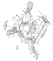
- Fig. 1 shows a perspective top view of a mowing device provided with a mower bar having mower discs arranged thereon, each one provided with three cutter blades,
- Fig. 2 shows a perspective top view of a part of the device from fig. 1, whereby the parts are taken apart.
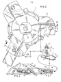
- Fig. 3 shows a top view of a second embodiment of the dish-like carrier,
- Fig. 4 shows a sectional view according to line IV-IV in fig. 3, wherein the cutter blade is taken apart.
- The device shown in fig. 1 for mowing agricultural crops is of a known type and consists substantially of a mower bar 1 which is moved forward over the field in the direction of the arrow P1 transverse of the longitudinal direction of mower bar 1. This is made possible by attaching the mower bar at one of its ends to a supporting
frame 2 which can be attached by means of a liftingframe 3 to for example the three-point suspension of an agricultural tractor (not shown). - Mower bar 1 is provided on the underside with
slide shoes 4 which slide over the ground. - The mower bar is provided on the upper side with four
dishes 5 which have a triangular form whereby at each angular pount a mower cutter blade 6 is arranged for rotation. - Driving of
discs 4 and cutter blades 6 is carried out by a gear wheel unit 7 accomodated in mower bar 1 which in each case drives a firstupright shaft 8 for amower disc 5. - The gear wheel unit 7 is set into rotation in a known manner by a
transmission 9 which is actuated from the power take-off 11 through a system ofropes 10. - It is noted finally that the other end of the mower bar 1 is formed with a
swath guide 12. - Essential features of the invention realted to the blade attachment and the form of the dish are now further elucidated with reference to fig. 2.
- In the embodiment shown,
dish 5 has a centralcircular part 13 which carries threearms 14 distributed at regular intervals along the periphery, these arms protruding beyond the substantiallycircular part 13. Thefront face 15 ofarm 14 facing the direction of rotation P2 is sloping back- and upwardly with respect to a lower lyingflange edge 16 ofcentral part 13. - Attached firmly to the underside of
upper part 14 of the arm is apin 17. The pin has an undercut 18underneath arm 14, in which undercut fits the fork-shaped end 19 of cutter blade 6. The spacing between the forks on either side ofrecess 20 of the cutter blade is such that it corresponds to the diameter ofundercut 18. - Cutter blade 6 is inserted into a closed
tubular holder 21, thistubular holder 21 being provided with two alignedcircular holes 22 lying one above the other, the diameter of which corresponds with that of thepin 17. - The
part 23 of the cutter blade to be inserted intoblade holder 21 is provided with aretaining lip 24 pressed out of the said part which co-operates with an opening 25 hollowed out of the upper or lower surface ofblade holder 21. - It is remarked finally that cutter blade 6 contains an active part 6' that is twisted at a determined angle C( relative to the
part 23. - It is noted that the lower edge of the cutter blade in this embodiment lies at the same height as that of the inclining
front surface 15 ofarm 14, see on the right of fig. 2. - Fitting of the cutter blade 6 is performed as follows. The user holds
blade holder 21 firmly with the one hand and places it ontopin 17, making sire that the undercut 18 comes to lie between the upper and lower plates ofholder 21. With the other hand he then inserts thepart 23 of cutter blade 6 into thetube 21, whereby thefork 19 comes to lie round the undercut 18. He inserts the cutter blade up to the point wherelip 24 falls into opening 25. This can be easily ascertained visually, see on the right in fig. 2. It is noted that the cutter blade can be inserted intoblade holder 21 in one way only so that the cutting edge of the cutter blade always points in the right direction. The cutter blade can however be turned over 180° on its longitudinal axis, whereby the retaining lip will slot into the other retaining hole of the holder. Alternatively, the holder can be turned over. It will be apparent from the above that the blade attachment is not only simple in construction but that it is also secure. - The
dish 5 can be attached to thevertical shaft 8 of mower bar 1 with or without cutter blade 6, since thisvertical shaft 8 is formed with a triangular elevatedportion 30. This elevated portion falls into a triangular recess 31 ofdish 5, following which the dish can be fixed ontoshaft 8 by means of a fastening bolt provided with aflange 32. - It will be apparent that the changing of cutter blades 6 can be performed while
dish 5 is either fitted or detached. - The invention is not limited to the embodiment described above. The
blade holder 21 can thus have not a closed form but an open C shape in order to achieve the same securing function for cutter blade 6. Therecess 20 of the fork-shaped end can have a form other than that shown, depending on the form of thepin 17 employed. - Retaining
lip 24 can be replaced by a separate retaining pin or spring. - In the embodiment according to fig. 3 and 4 the same reference numerals are used for the corresponding parts. Also here the
dish 5 is provided with acentral part 13 substantially being of circular form in top side view and further provided with three radially protrudingarms 14. Saidarm 14 is provided with a slopingfront face 15, which runs from the lower edge 16' in upward and backwards manner with respect to the location of direction P2. - The top face of the
arm 14 is provided with anorifice 35, in line with anon-circular hole 36 in aplate 37. Theplate 37 extends parallelly underneath thearm 14 and behind the slopingfront face 15, as is easily apparent from fig. 4. - In between the
lower plate 37 and the top surface ofarm 14 the cutter blade 6 can be pivotably arranged since the backside of theplates - To mounting the cutting blade 6 a bolt- and nutstructure is used. The
bolt 38 has a threadedshank 39, and a hammer-like head 40. The circumference of said head corresponds with the circumference of thehole 36 inplate 37, such that the head can be passed through it. - The
nut 41 has anexagonal part 42, and acircular part 43. Thecircular part 43 fits into theorifice 35 of plate-arm 14 and into the hole 20' of cutter blade 6. - To mount or replace cutter blade 6 it is necessary to have the unit; nut - bolt; inserted through the overlying holes 35, 20' and 36 and to turn the bolt over 90° as soon as the hammer-
head 40 is underneathplate 37. In this position thenut 41 will be turned, so as to clamp thehead 40 under theplate 37 and thepart 43 on top of theplate 37. In this manner the cutter blade 6 is easily fixed without further tools than a simple wrench tool. If desired the bottom face ofplate 37 can be provided with arecession 38 for taking up the hammer had 40 of thebolt 38, in order'to lock the bolt when turning thenut 41. - It is noticed that the
top edge 44 of the slopingfront face 15 lies higher than the part having theorifice 35 ofarm 14, so bringing the attachment structure of the cutter blade 6 fully behind thefront face 15, so avoiding unnecessary damage to thehammer head 40 ofbolt 38 andnut 41 as well. - It is further noticed that the lower edge 16' of the
front face 15 is on a lower or equal level as the active part 6" of cutter blade 6. - According to a further feature of the invention the cutter blade 6 is manufactures from a relatively
thin plate material 45, which is embedded in abody 46 of material having a lower wear resistency. The cutter blade is therefor easily to handle but is still self-shapening without the need to grind of the cutter edge itself. - The invention is not limited to the above described embodiments.
Claims (13)
Priority Applications (1)
| Application Number | Priority Date | Filing Date | Title |
|---|---|---|---|
| AT87200810T ATE67063T1 (en) | 1986-04-29 | 1987-04-29 | DISC CONSTRUCTION AND BLADE ATTACHMENT OF A MOWING DEVICE. |
Applications Claiming Priority (2)
| Application Number | Priority Date | Filing Date | Title |
|---|---|---|---|
| NL8601110 | 1986-04-29 | ||
| NL8601110A NL8601110A (en) | 1986-04-29 | 1986-04-29 | CUTTING DEVICE WITH IMPROVED BLADE ATTACHMENT. |
Publications (2)
| Publication Number | Publication Date |
|---|---|
| EP0244041A1 true EP0244041A1 (en) | 1987-11-04 |
| EP0244041B1 EP0244041B1 (en) | 1991-09-11 |
Family
ID=19847959
Family Applications (1)
| Application Number | Title | Priority Date | Filing Date |
|---|---|---|---|
| EP87200810A Expired - Lifetime EP0244041B1 (en) | 1986-04-29 | 1987-04-29 | Mowing device with improved disc configuration and blade attachment |
Country Status (10)
| Country | Link |
|---|---|
| US (1) | US4815264A (en) |
| EP (1) | EP0244041B1 (en) |
| JP (1) | JPS6394912A (en) |
| AT (1) | ATE67063T1 (en) |
| AU (1) | AU591556B2 (en) |
| CA (1) | CA1290945C (en) |
| DE (1) | DE3772826D1 (en) |
| DK (1) | DK165959C (en) |
| ES (1) | ES2024491B3 (en) |
| NL (1) | NL8601110A (en) |
Cited By (7)
| Publication number | Priority date | Publication date | Assignee | Title |
|---|---|---|---|---|
| EP0430281A1 (en) * | 1989-12-01 | 1991-06-05 | Trinecke Zelezarny | Lawn mower blade assembly |
| FR2772551A1 (en) * | 1997-12-19 | 1999-06-25 | Kuhn Sa | Lift for rotary mower to lift cut product |
| EP1110441A1 (en) * | 1999-12-24 | 2001-06-27 | Giuseppe Pompamea | Operative head for the cut of the grass and the bushes |
| GB2369765A (en) * | 2000-11-07 | 2002-06-12 | Sunbeam Corp | Blade assembly |
| EP2554047A1 (en) * | 2011-08-02 | 2013-02-06 | Giuliano Cavarzan | Blade or contrast blade |
| US8857038B2 (en) | 2011-09-07 | 2014-10-14 | Cnh Industrial America Llc | Disc cutterbar quick-change knife with retaining pin assembly |
| CN113557842A (en) * | 2021-07-09 | 2021-10-29 | 张宝斌 | Replaceable blade structure for lawn machine |
Families Citing this family (33)
| Publication number | Priority date | Publication date | Assignee | Title |
|---|---|---|---|---|
| FR2628596B1 (en) * | 1988-03-15 | 1991-09-06 | Kuhn Sa | DIRECT DRIVE MOWER |
| US5063731A (en) * | 1990-09-17 | 1991-11-12 | Hull Harold L | Brush and tree cutter blade |
| US5103882A (en) * | 1991-09-10 | 1992-04-14 | Milbourn David E | Rotary cutter wheel and removable tooth structure |
| SE504183C2 (en) * | 1993-12-01 | 1996-12-02 | Swing Cut Ab | Cutting tool with hover power |
| US5715663A (en) * | 1995-06-26 | 1998-02-10 | New Holland North America, Inc. | Crop mover for rotary disc cutter |
| US5791131A (en) * | 1996-04-22 | 1998-08-11 | Snapper, Inc. | Convertible mower blade |
| FR2774853B1 (en) * | 1999-02-15 | 2001-02-16 | Kuhn Sa | CUTTING MEMBER FOR A CUTTING MACHINE, PARTICULARLY A MOWER |
| US6834486B2 (en) * | 2003-03-12 | 2004-12-28 | Vermeer Manufacturing Company | Pivotal knife mounting arrangement |
| US7490459B2 (en) | 2003-03-12 | 2009-02-17 | Vermeer Manufacturing Company | Mowing device, a knife adapter for such a mowing device and a retainer for such a mowing device |
| US7290383B2 (en) * | 2004-09-03 | 2007-11-06 | David Harris | Trimmer blade |
| US7155889B2 (en) * | 2005-05-12 | 2007-01-02 | Eric David Myers | Modularized lawnmower replacement blade |
| US20070074497A1 (en) * | 2005-05-12 | 2007-04-05 | Myers Eric D | Modularized lawnmower replacement blade |
| US7775026B2 (en) * | 2008-06-12 | 2010-08-17 | Christopher Bever | Lawn mower blade assembly for quick blade replacement and associated methods |
| US7784254B2 (en) * | 2008-06-12 | 2010-08-31 | Christopher Bever | Lawn mower blade assembly having blade mount for quick blade replacement and associated methods |
| US7703268B2 (en) * | 2008-09-22 | 2010-04-27 | Deere & Company | Rotary cutter bar mechanism and blade pin coupling |
| US20100083506A1 (en) * | 2008-10-03 | 2010-04-08 | Bennett James A | Head section for a rotary cutting device including blades and individual cutting lines |
| BRMU8901415U2 (en) | 2009-06-09 | 2011-02-22 | Blount Ind Ltda | jointly introduced provisions knife and counter-knife pluggable on sugar cane cutting machine disc |
| USD669105S1 (en) | 2010-04-07 | 2012-10-16 | Blount, Inc. | Counter blade |
| DE102010054071A1 (en) | 2010-06-11 | 2011-12-15 | Eberhard Christ | Device for attaching knives to a mowing or mulching machine |
| EP2848148B1 (en) | 2011-09-29 | 2016-11-23 | Husqvarna AB | Quick-change blade system |
| US20130111863A1 (en) | 2011-11-07 | 2013-05-09 | Kondex Corporation | Disc Mower Blades |
| US8935909B2 (en) | 2012-06-12 | 2015-01-20 | Mtd Products Inc | Replaceable mower blade and assembly |
| US8931248B2 (en) | 2012-06-12 | 2015-01-13 | Mtd Products Inc | Replaceable mower blade assembly |
| DE102014201519A1 (en) * | 2014-01-28 | 2015-07-30 | Deere & Company | Mähgerat |
| US9545053B2 (en) * | 2014-04-25 | 2017-01-17 | Cnh Industrial America Llc | Spring plate configured to overlap with asymmetric/eccentric quick change knife nut for proper assembly |
| EP3142475A4 (en) * | 2014-05-12 | 2018-01-17 | Kondex Corporation | Slicing disc mower knives |
| US10362730B2 (en) | 2014-09-05 | 2019-07-30 | Mtd Products Inc | Quick change lawn mower blades |
| USD767639S1 (en) | 2015-04-09 | 2016-09-27 | Kondex Corporation | Sugar cane harvester base cutter knife |
| USD768727S1 (en) | 2015-04-09 | 2016-10-11 | Kondex Corporation | Corn header chopper knife |
| JP2020162506A (en) * | 2019-03-29 | 2020-10-08 | 本田技研工業株式会社 | Working structure of lawnmower |
| EP3935932A1 (en) * | 2020-07-07 | 2022-01-12 | Andreas Stihl AG & Co. KG | Cutting blade for a cutting head and cutting head for a motor powered strimmer |
| US11877535B2 (en) * | 2020-12-14 | 2024-01-23 | Kubota Corporation | Removable insert for mower blade and methods of using the same |
| US20230397529A1 (en) * | 2022-06-14 | 2023-12-14 | Deere & Company | Quick change blade for a rotating blade assembly of a mower implement |
Citations (14)
| Publication number | Priority date | Publication date | Assignee | Title |
|---|---|---|---|---|
| FR1563526A (en) * | 1967-05-25 | 1969-04-11 | ||
| DE1582364A1 (en) * | 1967-11-10 | 1970-04-30 | Friedrich Moertl | Mower with rotating cutting units, in which the cutting units are driven underneath them |
| DE1582345A1 (en) * | 1967-08-12 | 1970-05-14 | Friedrich Moertl | Easily detachable attachment of knives to rotating cutting tools |
| DE2043264A1 (en) * | 1969-09-18 | 1971-03-25 | Sperry Rand Corp , New Holland, Pa (V St A) | Knife attachment for rotating mowers |
| FR2072365A5 (en) | 1969-12-05 | 1971-09-24 | Massey Ferguson Services Nv | |
| DE2245183A1 (en) * | 1971-09-15 | 1973-03-22 | Stig Gunnar Hjelmquist | KNIVES FOR LAWN MOWERS |
| FR2260275A1 (en) * | 1974-02-13 | 1975-09-05 | Geier Horst | |
| FR2261698A1 (en) * | 1974-02-22 | 1975-09-19 | Kuhn Ets | Overhead-driven rotating cutter-blade for forage harvester - has cross-bar rotating drum and disc with cutter-blades |
| FR2370419A1 (en) * | 1976-11-15 | 1978-06-09 | Bernard Moteurs | Rotary lawn-mower blade - has grooved mounting nut moulded into body formed of resin impregnated and fibre reinforced plastics |
| US4229933A (en) * | 1979-03-07 | 1980-10-28 | Bernard Roy A | Separable mower blade |
| EP0022588A1 (en) | 1979-07-17 | 1981-01-21 | Petrus Wilhelmus Zweegers | Mower blade mounting |
| FR2517927A1 (en) * | 1981-12-15 | 1983-06-17 | Zweegers P | FASTENING CUTTING BLADES ON A ROTATING MOWER |
| FR2561488A1 (en) * | 1984-03-23 | 1985-09-27 | Sperry Corp | HARVEST LIFTING APPARATUS FOR DISK MOWER-CONDITIONER |
| NL8403911A (en) * | 1984-12-21 | 1986-07-16 | Multinorm Bv | Rotary mower with transverse beam - has pivoting knives secured by locking portions on pins in axial direction |
Family Cites Families (12)
| Publication number | Priority date | Publication date | Assignee | Title |
|---|---|---|---|---|
| US3321894A (en) * | 1964-12-03 | 1967-05-30 | Floyd M Ingram | Rotary blade structure |
| US3398517A (en) * | 1967-07-21 | 1968-08-27 | Dayco Corp | Lawnmower blade |
| US3555798A (en) * | 1967-09-02 | 1971-01-19 | Welger Geb | Mowing apparatus |
| US3570229A (en) * | 1968-10-28 | 1971-03-16 | Dayco Corp | Mower blade |
| US3614861A (en) * | 1969-05-26 | 1971-10-26 | Dayco Corp | Mower blade and method of making same |
| US3683606A (en) * | 1970-11-12 | 1972-08-15 | Harvey C Staines | Blade assembly for rotary lawn mower |
| US3911652A (en) * | 1974-01-11 | 1975-10-14 | Houle Elmer Richard | Safety blade for rotary lawn mowers |
| US3918241A (en) * | 1974-10-16 | 1975-11-11 | Herbert C Stillions | Cutting unit for rotary lawn mowers |
| FR2377755A1 (en) * | 1977-01-19 | 1978-08-18 | Vicon Nv | MOWER, LAWN MOWER OR SIMILAR MACHINE |
| DE2920244C2 (en) * | 1979-05-18 | 1986-10-23 | Klöckner-Humboldt-Deutz AG Zweigniederlassung Fahr, 7702 Gottmadingen | Rotary mower |
| US4471603A (en) * | 1983-03-29 | 1984-09-18 | Veltin Jr Arthur E | Detachable blades for rotary mowers |
| US4549390A (en) * | 1984-03-23 | 1985-10-29 | Sperry Corporation | Crop lifter for disc mower-conditioners |
-
1986
- 1986-04-29 NL NL8601110A patent/NL8601110A/en not_active Application Discontinuation
-
1987
- 1987-04-28 AU AU72141/87A patent/AU591556B2/en not_active Ceased
- 1987-04-28 US US07/043,415 patent/US4815264A/en not_active Expired - Fee Related
- 1987-04-28 JP JP62103431A patent/JPS6394912A/en active Pending
- 1987-04-28 CA CA000535749A patent/CA1290945C/en not_active Expired - Fee Related
- 1987-04-29 AT AT87200810T patent/ATE67063T1/en not_active IP Right Cessation
- 1987-04-29 DK DK219687A patent/DK165959C/en not_active IP Right Cessation
- 1987-04-29 EP EP87200810A patent/EP0244041B1/en not_active Expired - Lifetime
- 1987-04-29 DE DE8787200810T patent/DE3772826D1/en not_active Expired - Fee Related
- 1987-04-29 ES ES87200810T patent/ES2024491B3/en not_active Expired - Lifetime
Patent Citations (14)
| Publication number | Priority date | Publication date | Assignee | Title |
|---|---|---|---|---|
| FR1563526A (en) * | 1967-05-25 | 1969-04-11 | ||
| DE1582345A1 (en) * | 1967-08-12 | 1970-05-14 | Friedrich Moertl | Easily detachable attachment of knives to rotating cutting tools |
| DE1582364A1 (en) * | 1967-11-10 | 1970-04-30 | Friedrich Moertl | Mower with rotating cutting units, in which the cutting units are driven underneath them |
| DE2043264A1 (en) * | 1969-09-18 | 1971-03-25 | Sperry Rand Corp , New Holland, Pa (V St A) | Knife attachment for rotating mowers |
| FR2072365A5 (en) | 1969-12-05 | 1971-09-24 | Massey Ferguson Services Nv | |
| DE2245183A1 (en) * | 1971-09-15 | 1973-03-22 | Stig Gunnar Hjelmquist | KNIVES FOR LAWN MOWERS |
| FR2260275A1 (en) * | 1974-02-13 | 1975-09-05 | Geier Horst | |
| FR2261698A1 (en) * | 1974-02-22 | 1975-09-19 | Kuhn Ets | Overhead-driven rotating cutter-blade for forage harvester - has cross-bar rotating drum and disc with cutter-blades |
| FR2370419A1 (en) * | 1976-11-15 | 1978-06-09 | Bernard Moteurs | Rotary lawn-mower blade - has grooved mounting nut moulded into body formed of resin impregnated and fibre reinforced plastics |
| US4229933A (en) * | 1979-03-07 | 1980-10-28 | Bernard Roy A | Separable mower blade |
| EP0022588A1 (en) | 1979-07-17 | 1981-01-21 | Petrus Wilhelmus Zweegers | Mower blade mounting |
| FR2517927A1 (en) * | 1981-12-15 | 1983-06-17 | Zweegers P | FASTENING CUTTING BLADES ON A ROTATING MOWER |
| FR2561488A1 (en) * | 1984-03-23 | 1985-09-27 | Sperry Corp | HARVEST LIFTING APPARATUS FOR DISK MOWER-CONDITIONER |
| NL8403911A (en) * | 1984-12-21 | 1986-07-16 | Multinorm Bv | Rotary mower with transverse beam - has pivoting knives secured by locking portions on pins in axial direction |
Cited By (7)
| Publication number | Priority date | Publication date | Assignee | Title |
|---|---|---|---|---|
| EP0430281A1 (en) * | 1989-12-01 | 1991-06-05 | Trinecke Zelezarny | Lawn mower blade assembly |
| FR2772551A1 (en) * | 1997-12-19 | 1999-06-25 | Kuhn Sa | Lift for rotary mower to lift cut product |
| EP1110441A1 (en) * | 1999-12-24 | 2001-06-27 | Giuseppe Pompamea | Operative head for the cut of the grass and the bushes |
| GB2369765A (en) * | 2000-11-07 | 2002-06-12 | Sunbeam Corp | Blade assembly |
| EP2554047A1 (en) * | 2011-08-02 | 2013-02-06 | Giuliano Cavarzan | Blade or contrast blade |
| US8857038B2 (en) | 2011-09-07 | 2014-10-14 | Cnh Industrial America Llc | Disc cutterbar quick-change knife with retaining pin assembly |
| CN113557842A (en) * | 2021-07-09 | 2021-10-29 | 张宝斌 | Replaceable blade structure for lawn machine |
Also Published As
| Publication number | Publication date |
|---|---|
| DE3772826D1 (en) | 1991-10-17 |
| CA1290945C (en) | 1991-10-22 |
| ATE67063T1 (en) | 1991-09-15 |
| DK219687D0 (en) | 1987-04-29 |
| AU591556B2 (en) | 1989-12-07 |
| AU7214187A (en) | 1987-11-05 |
| JPS6394912A (en) | 1988-04-26 |
| DK219687A (en) | 1987-10-30 |
| EP0244041B1 (en) | 1991-09-11 |
| US4815264A (en) | 1989-03-28 |
| DK165959C (en) | 1993-07-05 |
| ES2024491B3 (en) | 1992-03-01 |
| NL8601110A (en) | 1987-11-16 |
| DK165959B (en) | 1993-02-22 |
Similar Documents
| Publication | Publication Date | Title |
|---|---|---|
| EP0244041B1 (en) | Mowing device with improved disc configuration and blade attachment | |
| US4733525A (en) | Cutting machine utilizable in agriculture, viticulture and aboriculture | |
| US10874048B2 (en) | Convertible cap and head system | |
| US6119350A (en) | Rotary cutting member for lawn trimmers | |
| US4525990A (en) | Device for mowing crop | |
| US5906091A (en) | Grain stalk lifter | |
| HUT74815A (en) | A cutting tool | |
| WO2012036572A2 (en) | Lawn mower working head for garden work | |
| US20030126849A1 (en) | Multiple saw pruning apparatus | |
| US4924665A (en) | Lawn mower blade assembly | |
| CA1103465A (en) | Device, especially for the use on grassed areas and the like | |
| US4686819A (en) | Mulcher attachment | |
| US5768867A (en) | Rotary blade for cutting grass and the like | |
| US8001753B2 (en) | Grass raking system | |
| US4479302A (en) | Trimmer for lawn sprinklers | |
| US4409781A (en) | Thatching tool for rotary lawn mower | |
| US3049852A (en) | Crop harvesting attachment for combines | |
| US20010037635A1 (en) | Crop lifter | |
| CN219395455U (en) | Orchard weeding device | |
| JPS6119625Y2 (en) | ||
| US2465543A (en) | Weed eradicating attachment for lawn mowers | |
| JP2024022948A (en) | Vine cutting device and working machine equipped with a vine cutting device | |
| KR101063852B1 (en) | Grounding cap for ground close mowing | |
| EP0202957A1 (en) | Detachable blades for drum mowers | |
| JPS6131642Y2 (en) |
Legal Events
| Date | Code | Title | Description |
|---|---|---|---|
| PUAI | Public reference made under article 153(3) epc to a published international application that has entered the european phase |
Free format text: ORIGINAL CODE: 0009012 |
|
| AK | Designated contracting states |
Kind code of ref document: A1 Designated state(s): AT BE CH DE ES FR GB GR IT LI LU NL SE |
|
| 17P | Request for examination filed |
Effective date: 19880427 |
|
| 17Q | First examination report despatched |
Effective date: 19891102 |
|
| GRAA | (expected) grant |
Free format text: ORIGINAL CODE: 0009210 |
|
| AK | Designated contracting states |
Kind code of ref document: B1 Designated state(s): AT BE CH DE ES FR GB GR IT LI LU NL SE |
|
| PG25 | Lapsed in a contracting state [announced via postgrant information from national office to epo] |
Ref country code: IT Free format text: LAPSE BECAUSE OF FAILURE TO SUBMIT A TRANSLATION OF THE DESCRIPTION OR TO PAY THE FEE WITHIN THE PRESCRIBED TIME-LIMIT;WARNING: LAPSES OF ITALIAN PATENTS WITH EFFECTIVE DATE BEFORE 2007 MAY HAVE OCCURRED AT ANY TIME BEFORE 2007. THE CORRECT EFFECTIVE DATE MAY BE DIFFERENT FROM THE ONE RECORDED. Effective date: 19910911 Ref country code: LI Effective date: 19910911 Ref country code: BE Effective date: 19910911 Ref country code: CH Effective date: 19910911 Ref country code: AT Effective date: 19910911 Ref country code: SE Effective date: 19910911 Ref country code: GR Free format text: LAPSE BECAUSE OF FAILURE TO SUBMIT A TRANSLATION OF THE DESCRIPTION OR TO PAY THE FEE WITHIN THE PRESCRIBED TIME-LIMIT Effective date: 19910911 |
|
| REF | Corresponds to: |
Ref document number: 67063 Country of ref document: AT Date of ref document: 19910915 Kind code of ref document: T |
|
| REF | Corresponds to: |
Ref document number: 3772826 Country of ref document: DE Date of ref document: 19911017 |
|
| ET | Fr: translation filed | ||
| REG | Reference to a national code |
Ref country code: CH Ref legal event code: PL |
|
| REG | Reference to a national code |
Ref country code: ES Ref legal event code: FG2A Ref document number: 2024491 Country of ref document: ES Kind code of ref document: B3 |
|
| PG25 | Lapsed in a contracting state [announced via postgrant information from national office to epo] |
Ref country code: LU Free format text: LAPSE BECAUSE OF NON-PAYMENT OF DUE FEES Effective date: 19920430 |
|
| PLBI | Opposition filed |
Free format text: ORIGINAL CODE: 0009260 |
|
| 26 | Opposition filed |
Opponent name: C. VAN DER LELY N.V. Effective date: 19920605 |
|
| NLR1 | Nl: opposition has been filed with the epo |
Opponent name: C. VAN DER LELY N.V. |
|
| PLBM | Termination of opposition procedure: date of legal effect published |
Free format text: ORIGINAL CODE: 0009276 |
|
| STAA | Information on the status of an ep patent application or granted ep patent |
Free format text: STATUS: OPPOSITION PROCEDURE CLOSED |
|
| 27C | Opposition proceedings terminated |
Effective date: 19930802 |
|
| PGFP | Annual fee paid to national office [announced via postgrant information from national office to epo] |
Ref country code: DE Payment date: 19940429 Year of fee payment: 8 Ref country code: ES Payment date: 19940429 Year of fee payment: 8 Ref country code: FR Payment date: 19940429 Year of fee payment: 8 |
|
| PGFP | Annual fee paid to national office [announced via postgrant information from national office to epo] |
Ref country code: NL Payment date: 19940430 Year of fee payment: 8 |
|
| PGFP | Annual fee paid to national office [announced via postgrant information from national office to epo] |
Ref country code: GB Payment date: 19940510 Year of fee payment: 8 |
|
| NLR2 | Nl: decision of opposition | ||
| PG25 | Lapsed in a contracting state [announced via postgrant information from national office to epo] |
Ref country code: GB Effective date: 19950429 |
|
| PG25 | Lapsed in a contracting state [announced via postgrant information from national office to epo] |
Ref country code: ES Free format text: LAPSE BECAUSE OF NON-PAYMENT OF DUE FEES Effective date: 19950503 |
|
| PG25 | Lapsed in a contracting state [announced via postgrant information from national office to epo] |
Ref country code: NL Effective date: 19951101 |
|
| PG25 | Lapsed in a contracting state [announced via postgrant information from national office to epo] |
Ref country code: FR Effective date: 19951229 |
|
| NLV4 | Nl: lapsed or anulled due to non-payment of the annual fee |
Effective date: 19951101 |
|
| GBPC | Gb: european patent ceased through non-payment of renewal fee |
Effective date: 19950429 |
|
| PG25 | Lapsed in a contracting state [announced via postgrant information from national office to epo] |
Ref country code: DE Effective date: 19960103 |
|
| REG | Reference to a national code |
Ref country code: FR Ref legal event code: ST |
|
| REG | Reference to a national code |
Ref country code: ES Ref legal event code: FD2A Effective date: 19990201 |