EP0243885A2 - Method and apparatus for setting up a short wave radio network communication - Google Patents
Method and apparatus for setting up a short wave radio network communication Download PDFInfo
- Publication number
- EP0243885A2 EP0243885A2 EP87105972A EP87105972A EP0243885A2 EP 0243885 A2 EP0243885 A2 EP 0243885A2 EP 87105972 A EP87105972 A EP 87105972A EP 87105972 A EP87105972 A EP 87105972A EP 0243885 A2 EP0243885 A2 EP 0243885A2
- Authority
- EP
- European Patent Office
- Prior art keywords
- signal
- synchronization signal
- signals
- frequency
- noise
- Prior art date
- Legal status (The legal status is an assumption and is not a legal conclusion. Google has not performed a legal analysis and makes no representation as to the accuracy of the status listed.)
- Granted
Links
Images

Classifications
-
- H—ELECTRICITY
- H04—ELECTRIC COMMUNICATION TECHNIQUE
- H04B—TRANSMISSION
- H04B7/00—Radio transmission systems, i.e. using radiation field
- H04B7/24—Radio transmission systems, i.e. using radiation field for communication between two or more posts
Definitions
- the invention relates to a method for establishing a connection in shortwave radio networks with a plurality of stations having a transmitter and / or a receiver, by means of a call signal emitted by a transmitter and consisting of a synchronization signal and an address signal.
- Shortwave connections mainly use the propagation of spatial waves, which are reflected on the ionosphere, in order to realize a message transmission over large distances.
- a Jardinwetlen connection such as noise-like channel interference
- time-varying, dispersive channel behavior and the presence of selective interferers this type of transmission has recently gained in importance, thanks to new microprocessor technologies and low costs compared to satellites.
- Today's usual transmissions are carried out for the economical use of the frequency supply by means of single-sideband technology, with the frequency of the signal from the audio frequency band (300 Hz to 3.4 kHz) being carried out on the transmitter side into a selected HF band and the reverse from the HF receiver Surgery is performed.
- the received signal is passed on to demodulator and decoder circuits in the LF range.
- the HF receivers have automatic gain controls, with the total power or voltage forming the controlled variable within the selected receive channel bandwidth.
- different noise and useful levels occur at the output, within wide limits. In particular, selective interferers, which have more signal energy than the useful signal, are frequently encountered and the channel is then usually considered to be occupied.
- the selective call transmitters and receivers of the individual stations are accommodated in their modulator or demodulator block.
- the call signals are composed of a set of suitable amplitude-time functions which can be recognized by the individual receivers in the channel noise and distinguished from one another. Even if the transmission quality is poor, on the one hand no wrong stations and on the other hand the desired stations should always be activated.
- a distinctive synchronization signal which is adapted to the transmission channel is used and which consists of narrow-band mark and space signals which form the partial signals of a diversity pair.
- the use of the synchronization signal according to the invention has the advantage that, at the same time as the frequency offset is determined, bit synchronization between the stations is made possible by determining the phase of the modulation signal modulating the carrier signal at the receiving location.
- the modulation signal is obtained mathematically precisely since the expected signal is known.
- an increase in the probability of incorrect synchronization caused by the presence of certain disturbances can be largely avoided.
- the structure of the synchronization signal from narrow-band mark and space signals that contain the partial signals of a diversity Forming a pair opens up the possibility of separate detection of these partial signals, which considerably increases the reliability of the connection establishment. This is because the probability that there is an interferer striking the marking signal at the same time in both diversity channels is zero.
- a frequency offset of a few Hz between the interferer and the marker signal is not critical, since 500 subchannels of 1 Hz each are examined in the range between 250 and 750 Hz using a special signal processing operation.
- the invention further relates to a device for carrying out the method mentioned, with a synchronization signal receiver.
- the device according to the invention is characterized in that the synchronization signal receiver has means for the independent detection and evaluation of the two partial signals of the diversity pair as well as means for comparing the results obtained therefrom.
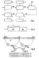
- a short-wave connection that is commonly used today consists of a transmitter 1 and a receiver 2 between which the signals are transmitted via a transmission medium 3.
- the transmitter-side data input takes place in a modulator / code circuit 4, to which a time base 5 is assigned.
- the output signal of the modulator / encoder circuit 4 is an LF signal in the audio frequency band between 300 Hz and 3.4 kHz.
- the transmitter 1 which is an HF SSB transmitter, performs a frequency translation into a selected HF band.
- a frequency base 6 in the range of the HF band is assigned to the transmitter 1.
- the RF output signal of the transmitter 1 emitted in the time-variant transmission medium 3 is, for example, in the range between 3 and 30 MHz.
- Additive noise ST is added to this HF signal in transmission medium 3.
- the received RF signal is transferred to an LF signal in the transmitter's audio frequency band and fed to a demodulator / decoder circuit 7, which is assigned a time base 5'.
- the data is output at the output of the demodulator / decoder circuit 7.
- a shortwave radio network forms a so-called selective call network
- each of the stations involved has a selective call transmitter and receiver, which are accommodated in the modulator and demodulator blocks 4 and 7 of the arrangement in FIG. 1 (see, for example, DE-PS 32 11 325).
- the signals for calling, the so-called call signals are composed of a set of suitable amplitude-time functions that can be recognized by the individual receivers in the channel noise and distinguished from one another.
- FIG. 2 schematically shows a call signal used in the method according to the invention. As shown, this consists of a synchronization signal SS and an address signal AS.
- the receiver looks at time intervals of length T and decides whether or not a synchronization signal SS is present within the respective interval.
- the observation intervals are weighted using a window function (FIG. 4).
- a time period of 2 s is preferably reserved for the synchronization signal SS. So that at least one observation interval completely overlaps with the transmitter signal in the initial, desynchronous state, T may not exceed 3 s.
- the length T of the observation interval is only sensibly selected if it is shorter than the coherence time T of the received signal. With the selected time window, T c > T / 2 should be.
- the receiver does not know the exact carrier frequency of the transmitter, but there is an expectation range in which a call signal occurs with the highest probability.
- this expected range can be up to 500 Hz and, in the exemplary embodiment described, is ⁇ 234 Hz.
- a call signal should be perfectly detectable and its frequency offset should be accurate to at least ⁇ 1 Hz depending on the signal / noise ratio be determined. Clear detection should be possible for a signal / noise ratio of up to at least -24 dB, based on 2 kHz bandwidth.
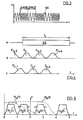
- synchronization signal SS is selected for the synchronization signal SS, which is adapted to the transmission channel and can be easily detected in a disturbed environment.
- This synchronization signal SS emitted during the time period T is a low-frequency one Carrier signal which frequency modulates with a square wave function and is also known as an FSK signal. As shown, it consists of "mark" and "space” signals.
- the synchronization signal SS enables bit synchronization between the stations simultaneously with the determination of the frequency offset, in that the phase of the modulation signal is determined at the receiving location.
- the modulation frequency is quartz-precise and is known to the receiver.
- the phase should be able to be determined with an accuracy of at least 0.5 rad.
- the mark and space signals each an AM signal in themselves, are narrow-band- ⁇ ig in order to ensure a uniform variation of the most intense spectral components with selective fading.
- the frequency spacing between them is chosen to be as large as possible in order to obtain two signals decorrelated with respect to selective fading, but both of which lie within the same channel.
- the keying frequency is significantly higher than the fading frequency and differences in transit time should play a minor role.
- a modulation frequency of 16 Hz is selected, a baseband carrier around 2 kHz for the mark signal and a baseband carrier around 500 Hz for the space signal.
- both carriers can be varied in order to allow adaptive shifts of the AM signals do.
- Mark and space signals are considered by the receiver as an AM diversity pair and detected separately. This has the additional advantage that with uneven interference signal distribution on the channel, the detection reliability increases significantly.
- the overall signal has constant power (no FSK, AM component), enables non-linear amplifier operation and optimal use of the transmitter stage and is also clearly distinguishable from selective interference signals.
- the HF receiver If the HF receiver is in automatic scan mode, for example SELSCAN (registered trademark of Rockwell-Collins), it periodically examines a certain number of programmed channels for a possible synchronization signal. This is sent out by the transmitter as long as a scan cycle lasts. After successful detection of a synchronization signal, the receiver stops the scanning operation and waits for the address signal AS (FIG. 2).
- SELSCAN registered trademark of Rockwell-Collins
- the receiver looks at time intervals of length T and decides whether a synchronization signal is present within the respective intervals.
- the observation intervals are weighted with a window function. 4
- a synchronization signal SS of length T is shown in line a, the lines of the observation intervals in lines b and c (not to scale), specifically the even-numbered windows Fn-2, F n , F n + 2 in line b etc., and in line c, the ungeradierei- gen F n-1, F n + 1, etc.
- the Length T of an observation interval is 1 s and is determined by the length T of the synchronization signal SS and the coherence time T of the channel.
- Detection values of two overlapping observation intervals are practically statistically independent due to the window function, so that approximately 2 detection values can be obtained during 2T of a time period T of the transmission of the synchronization signal SS.
- the suitable selection of the window function enables high dynamics in the spectral range after the fast Fourier transformation FFT has been carried out (FIG. 7a).
- the receiver therefore continuously accumulates detection values in a "lossy integrator" or in a digital low-pass filter.
- the desired components crystallize from the stochastic components bit by bit, similar to a puzzle, so that up to a certain usable integration time, an increasingly sharper image of the synchronization signal is created, from which both the carrier frequency and the phase angle are determined can.
- the minimum signal / noise ratio required for successful detection and synchronization can thus be dependent within certain limits on the duration of the transmission of the synchronization signal, down to about -24 dB at 2 kHz noise bandwidth.
- synchronization signal SS After the transmission of the synchronization signal SS and its detection, all selective call receivers on the same call channel are synchronized.
- the synchronization signal SS is immediately followed by an address signal AS which makes the actual selective call.
- word synchronization that is to say the complete time synchronization between transmitter and receiver, is then also established.
- the receiver carries out two independent detections and evaluations of the two partial signals of the diversity pair and subsequently compares the results.
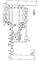
- the two additively disturbed received signals are converted into a sequence of N numerical values by an A / D converter after prior analog processing (filtering and mixing) during each observation period T.
- the term receiver refers to a demodulator / decoder in the LF frequency range (cf. demodulator / decoder 7 in FIG. 1).
- the received signal r (t) is first passed through an overall channel filter 8 with a pass band from 300 Hz to 3.4 kHz, to the output of which two paths 9 A and 9 B are connected for the two partial signals of the diversity pair.
- an overall channel filter 8 with a pass band from 300 Hz to 3.4 kHz, to the output of which two paths 9 A and 9 B are connected for the two partial signals of the diversity pair.
- a first mixer 10 A or 10 B With a first mixer 10 A or 10 B , the signals in each path with a variable Oscillator mixed up into the same reception band A or B (cf. FIG. 6) and then filtered with an IF filter 11 A , 11 8 , whose pass curve is approximately 4.5 kHz.
- An AGC amplifier 12 is connected to each of the IF filters 11 A , 11 B.
- the two frequency ranges Mark and Space of 500 Hz bandwidth are mixed down in each path 9 A , 9 B with a second mixer 13 into the baseband from 250 Hz to 750 Hz, which is used as a fixed processing band.
- This is followed by filtering with an image frequency filter 14 A , 14 B for the purpose of attenuation.
- the output signals rA (t) and rB (t) of the image frequency filters 14 A and 14 B each pass into a sampler 15 with a downstream A / D converter 16, at the output of which a signal vector r A or r B lies.
- the signal vectors r A and r B each contain N values which initially enter a buffer memory 17, from where they can be called up by a signal processor.
- the buffer memory 17 consists of three partial memories of size N / 2; one part is available to the A / D converter 16 and two parts to the processor for processing.
- the dashed curve H 8 (f) corresponds to the transmission characteristic of the overall channel filter 8, the dash-dash curve H (f) to that of the image frequency filters 14A, 14, and the arrow P represents the scanning signal.
- the sampling frequency is shown as 2.048 kHz.
- the characteristic curve H c (f) represents the fixed processing band (baseband from 250 to 750 Hz), the characteristic curve H A (f) the variable reception band for the one partial signal (path 9 A , FIG. 5) and the characteristic curve H B (f ) the variable reception band for the other partial signal (path 9 B , Fig. 5) of the diversity pair.
- H 11 (f) is the transmission curve of the IF filter 11 A , 11 B (FIG. 5).
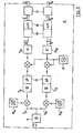
- FIG. 7 shows the individual functional levels of the signal processing as it is carried out by the corresponding part of the synchronization receiver formed by a signal processor.
- signal vector r A only half of the diversity receiver is considered (signal vector r A ), because it is completely symmetrical.
- the second signal vector ( r B ) With the second signal vector ( r B ) the same signal processing takes place in the processor as with the first ( r A ), only with other numerical values.
- FIG. 7 is divided into two figures, 7a and 7b.
- Fig. 7a shows the signal processing up to the so-called hypothesis decision
- Fig. 7b shows the remaining functional levels.
- the result of the signal processor after the numerical signal processing contains the selected hypothesis whether a synchronization signal is present (H 1 ) or not (H).
- H 1 a synchronization signal is present
- the numerical signal processing which is carried out in real time, essentially checks whether the received vector r of the N-dimensional vector space R lies in the decision area of the hypothesis H 1 or H o .
- the decision area is in the form of an N-dimensional cone with the tip in the origin of the room IR.
- the amount of r (or the overall performance of the received signal) does not affect this decision. Because the hypothesis is based solely on the direction of r.
- the decision area is therefore an N-dimensional solid angle area.
- the first arithmetic operation that takes the N values of the signal vector r A (and also r B , which, as mentioned, is not shown) are subjected to the weighting with the window function F, followed by a Fourier transformation.
- the latter forms the vector r of the room TR in r of the room TR '.
- the Fourier transform used is a so-called fast Fourier transform FFT, which represents the computationally faster version of the discrete Fourier transform. Since the synchronization signal is periodic in nature, the transition into the frequency range at 7 'results in a separation into actual signal and noise components This separation in the manner of a filtering is the better, the higher the spectral resolution of the Fourier transformation. The resolution in turn is determined by the observation time T or the "size" of the FFT.
- the part of the signal processing that follows the Fourier transformation FFT is used for demodulating (identifying) the diversity pair, for noise estimation, for signal integration (accumulation) for hard-to-detect useful signals and for making hypothesis decisions. All these parts of the signal processing are of course solved as numerical operations in the signal processor.
- a demodulation specially adapted to the marking signal is now carried out in the previously calculated spectrum, with as many characteristic features as possible being determined.
- Demodulation takes place in the frequency domain.
- the method used is called the frequency autocorrelation function: S (f + ⁇ .) Is the upper sideband, S (f- ⁇ ) the lower sideband and S (f) is the carrier, S * is the conjugate complex value.
- This numerical synchronization signal demodulation is shown in FIG. 8. It can be seen that from the carrier r ' -m (component of the vector 7' for S (f)), and from the upper and lower sidebands r ' -m + ⁇ and r' -m- ⁇ (components of the vector r ' for S (f + ⁇ ) or S (f- ⁇ )) is assumed.
- the values r ' -m- ⁇ r' -m + ⁇ and r ' -m are in a frequency base value memory 24.
- the conjugate complex value of r' -m- ⁇ and of r ' is in each case with r' and multiplied by r ' m + ⁇ and the results of these multiplications are added and subtracted, resulting in the values for the vector Z ⁇ (numerical version of the frequency autocorrelation function) and for the error vector ⁇ Z ⁇ are formed.
- These values are stored in corresponding memories 25 and 26 for the numerical version of the frequency autocorrelation function and for the error vector.
- the noise stimulator is identified in FIG. 7a by reference numeral 20.
- the decision about the hypotheses as to whether or not a synchronization signal is present must be assessed on the basis of the signal / noise ratio since the receiver knows neither signal energy based on noise power in advance.
- the decision threshold is derived from the false alarm probability.
- the determination of the noise (corresponds to the estimated value of the variance Z ⁇ ) is done by means of the spectral support values in the vicinity of r ' -m , r' -m- ⁇ and r ' -m + ⁇ (FIG. 8) and in this way provides a local power density in the vicinity of the synchronization signal.
- the selected base values are demodulated in exactly the same way as the sidebands are demodulated in the demodulation described with reference to FIG. 8. Only is no longer equal to 16.
- the noise stimulation is supposed to be a combined variable X be made of noise energy and noise assessment in order to detect both "white" noise and interference signals in their influence.
- the detected Z ⁇ are based on the local noise variable ( x ) standardized and these standardized values ( 1 , ⁇ 1 ) are passed to a decision maker 21, whereby for the components of 1 and ⁇ 1 applies:
- an accumulation in the form of digital filters is provided, which values 1 and ⁇ 1 used over several observation intervals, which leads to an improvement in the signal / Ge noise ratio leads.
- An example of such a filtering is designated by the reference symbol 22 in FIG. 7a.
- the gain can easily be 14 dB with an accumulation of 20 observation intervals.
- False signals are signals similar to the synchronization signal with, for example, almost the same modulation frequency or a short presence time.
- the carrier for demodulation and the sidebands r 'and r' m + 16 ' r' m-16 becomes a second noise statistic are formed and the two noise statistics are divided, the quotient deciding which noise statistics to use.
- the combined variable already mentioned x generated.
- test variables 1 ⁇ 1 -m , 1 ' -m and ⁇ 1' -m which result from N samples of a time function of duration T or more T, are checked in decision-maker 21 (decision gate).
- decision-maker 21 decision gate
- the variables 1 -m and ⁇ 1 -m are first used for each frequency m (266S m ⁇ 734).
- the interval overlap is used in the fast Fourier transform tion FFT deliberately used to recover energy losses through the window function F.
- be dependent.
- the size a of the first test is itself a function of the noise statistics; For a certain number of noise support values used, an optimal threshold can be specified, which is stored in a RAM table. Meets
- a diversity combining 23 therefore only takes place if the hypothesis H 1 has been decided on both channels A and B. In the case of the combination, this results in a gain of 3 dB for the phase and frequency determination.
- the use of frequency diversity is itself very profitable, since often a part of the channel is severely disturbed or suffers from fading.
- the frequency and phase stimulation are summed up carried out. If H 1 is met at several locations on the frequency axis, then the frequency with the largest
- the synchronization signal receiver working according to the described method has the advantage that thanks to complete software real-time Realisa tion of the receiver many parameters can be optimized and varied; for example, the detection sensitivity can be optimized for a given estimation reliability.
- the main advantages of the receiver are the great flexibility in the specification, in the age-free implementation and in achieving detection reliability that is close to that which is theoretically attainable. This is made possible by the operational sequence shown in FIG. 7 and by the digital signal processing, which only enables the required precision.
- the system can be expanded to several transmission channels for scan operation without additional effort and micro-scan operation (division of a channel of 3 kHz width into 500 Hz subchannels) is also possible.
- frequency and phase drifts can be continuously corrected after detection of the degrees of freedom, and instead of the synchronization signal, a slow data connection can occur in a similar manner by replacing the now known degrees of freedom with new ones.
- a selective call system can be created and a data modem for low baud rates can be derived from it, in which data occurs instead of the selective call address.
- a connection is established without changing the channel, i.e. almost always guaranteed without any intervention from the synthesizer.
- ECCM operation allows you to hide your own signal behind strong (e.g. hostile) transmitters. This prevents a rapid bearing or malfunction during network construction or during network control / network operation.
- strong e.g. hostile
Abstract
Description
Die Erfindung betrifft ein Verfahren zum Verbindungsaufbau bei Kurzwellenfunknetzen mit mehreren einen Sender und/oder einen Empfänger aufweisenden Stationen, mittels eines von einem Sender ausgesandten und aus einem Synchronisations- und aus einem Adress-Signal bestehenden Rufsignals.The invention relates to a method for establishing a connection in shortwave radio networks with a plurality of stations having a transmitter and / or a receiver, by means of a call signal emitted by a transmitter and consisting of a synchronization signal and an address signal.
Kurzwellenverbindungen benützen hauptsächlich die Ausbreitung von Raumwellen, die an der Ionosphäre reflektiert werden, um eine Nachrichtenübertragung über grosse Distanzen zu realisieren. Trotz der Unzulänglichkeiten des Uebertragungskanals für eine Raumwetlenverbindung - wie rauschähnliche Kanalstörungen, zeitvariantes, dispersives Kanalverhalten und Anwesenheit selektiver Störer - gewinnt diese Uebermittlungsart in jüngster Zeit, dank neuer Mikroprozessortechniken und im Vergleich zu Satelliten geringen Kosten, stark an Bedeutung.Shortwave connections mainly use the propagation of spatial waves, which are reflected on the ionosphere, in order to realize a message transmission over large distances. Despite the inadequacies of the transmission channel for a Raumwetlen connection - such as noise-like channel interference, time-varying, dispersive channel behavior and the presence of selective interferers - this type of transmission has recently gained in importance, thanks to new microprocessor technologies and low costs compared to satellites.
Spezielle Probleme ergeben sich beim Verbindungsaufbau, weil zwischen Sender- und Empfängerfrequenz immer eine mehr oder weniger grosse Frequenzdifferenz (Offset) besteht und weil vor der Verbindungsaufnahme zwischen Sender und Empfänger keine Zeitsynchronisation gegeben ist.Special problems arise when establishing a connection because there is always a greater or lesser frequency difference (offset) between the transmitter and receiver frequencies and because there is no time synchronization between the transmitter and receiver before the connection is established.
Heute übliche Uebertragungen erfolgen zur ökonomischen Verwendung des Frequenzvorrats mittels Einseitenbandtechnik, wobei senderseitig eine Frequenztranslation des Signals aus dem Tonfrequenzband (300 Hz bis 3,4 kHz) in ein gewähltes HF-Band vorgenommen und vom HF-Empfänger die umgekehrte Operation durchgeführt wird. Das empfangene Signal wird im NF-Bereich an Demodulator- und Decoderschaltungen weitergegeben. Die HF-Empfänger verfügen über automatische Verstärkungsregelungen, wobei die Gesamtleistung oder -spannung innerhalb der gewählten Empfangskanalbandbreite die Regelgrösse bildet. Dabei stellen sich am Ausgang je nach spektraler Belegung von Nutz-und Störsignal unterschiedliche Geräusch- und Nutzpegel ein und zwar in weiten Grenzen. Insbesondere sind selektive Störer, die mehr Signalenergie aufweisen als das Nutzsignal, häufig anzutreffen und der Kanal gilt dann zumeist als besetzt.Today's usual transmissions are carried out for the economical use of the frequency supply by means of single-sideband technology, with the frequency of the signal from the audio frequency band (300 Hz to 3.4 kHz) being carried out on the transmitter side into a selected HF band and the reverse from the HF receiver Surgery is performed. The received signal is passed on to demodulator and decoder circuits in the LF range. The HF receivers have automatic gain controls, with the total power or voltage forming the controlled variable within the selected receive channel bandwidth. Depending on the spectral assignment of the useful signal and the interference signal, different noise and useful levels occur at the output, within wide limits. In particular, selective interferers, which have more signal energy than the useful signal, are frequently encountered and the channel is then usually considered to be occupied.
Bei einem Selektivrufnetz sollen sich verschiedene Stationen einzeln oder mit einem Sammelwort aktivieren lassen. Die Selektivrufsender und -empfänger der einzelnen Stationen sind in deren Modulator- bzw. Demodulatorblock untergebracht. Die Rufsignale setzen sich aus einem Satz von geeigneten Amplituden-Zeit-Funktionen zusammen, die von den einzelnen Empfängern im Kanalgeräusch erkannt und voneinander unterschieden werden können. Auch bei schlechter Uebertragungsqualität sollen einerseits keine falschen Stationen und anderseits die gewünschten Stationen immer aktiviert werden.With a selective call network, different stations should be activated individually or with a collective word. The selective call transmitters and receivers of the individual stations are accommodated in their modulator or demodulator block. The call signals are composed of a set of suitable amplitude-time functions which can be recognized by the individual receivers in the channel noise and distinguished from one another. Even if the transmission quality is poor, on the one hand no wrong stations and on the other hand the desired stations should always be activated.
Heute übliche Pilottonübertragungen vermögen diese Anforderungen nicht zu erfüllen, weil die Fehlsynchronisations-Wahrscheinlichkeit mit der Anwesenheit bestimmter Störungen ansteigt.Today's pilot tone transmissions are unable to meet these requirements because the probability of incorrect synchronization increases with the presence of certain disturbances.
Es ist bekannt, zusätzlich zu den Sender-Empfängerteilen der Stationen ein relativ aufwendiges Gerätesystem zu verwenden, mit welchem feststellbar ist, welcher Kanal frei und ungestört von Nachbarsendern ist und wie die momentanen Ausbreitungsbedingungen über die Ionosphäre sind (Frequency Management System, Defence Electronics, Mai 1980, S. 21, 22). Ein vollautomatischer Aufbau einer Kurzwellenverbindung ist jedoch mit diesem System nicht möglich. Bei bewusst gewollten Störern (ECM) nützt eine vorgängige Kanalanalyse nur wenig, da der benützte Kanal jeweils sofort gestört wird.It is known to use a relatively complex device system in addition to the transceiver parts of the stations, with which it can be determined which channel is free and undisturbed by neighboring transmitters and how that current propagation conditions across the ionosphere are (Frequency Management System, Defense Electronics, May 1980, pp. 21, 22). However, a fully automatic establishment of a shortwave connection is not possible with this system. In the case of deliberately wanted interference (ECM), a previous channel analysis is of little use, since the channel used is immediately disturbed.
Es ist die Aufgabe der Erfindung, ein Verfahren der eingangs genannten Art anzugeben, mit welchem der Aufbau von Kurzwellenverbindungen zwischen den Stationen eines Funknetzes vollautomatisch durchführbar ist, wobei auch bei schlechter Uebertragungsqualität immer nur ausschliesslich die gewünschten Stationen aktiviert werden sollen.It is the object of the invention to provide a method of the type mentioned at the outset with which the establishment of short-wave connections between the stations of a radio network can be carried out fully automatically, even if the transmission quality is poor, only the desired stations are to be activated.
Diese Aufgabe wird erfindungsgemäss dadurch gelöst, dass ein markantes und an den Uebertragungskanal angepasstes Synchronisationssignal verwendet wird, welches aus schmalbandigen Mark- und Space-Signalen besteht, welche die Teilsignale eines Diversity-Paares bilden.This object is achieved according to the invention in that a distinctive synchronization signal which is adapted to the transmission channel is used and which consists of narrow-band mark and space signals which form the partial signals of a diversity pair.
Die Verwendung des erfindungsgemässen Synchronisationssignals hat den Vorteil, dass es gleichzeitig mit der Bestimmung des Frequenzoffsets eine Bitsynchronisation zwischen den Stationen ermöglicht, indem die Phase des das Trägersignal modulierenden Modulationssignals am Empfangsort bestimmt wird. Das Modulationssignal wird mathematisch exakt gewonnen, da das erwartete Signal bekannt ist. Dadurch ist ein durch die Anwesenheit bestimmter Störungen verursachter Anstieg der Fehlsynchronisations-Wahrscheinlichkeit weitgehend vermeidbar. Der Aufbau des Synchronisationssignals aus schmalbandigen Mark- und Space- Signalen, die die Teilsignale eines Diversity-Paares bilden, eröffnet die Möglichkeit einer separaten Detektion dieser Teilsignale, was die Zuverlässigkeit des Verbindungsaufbaus ganz beträchtlich erhöht. Denn die Wahrscheinlichkeit, das in beiden Diversity-Kanälen ein gleichzeitig genau auf das Markierungssignal treffender Störer vorhanden ist, ist gleich Null. Eine Frequenzablage von wenigen Hz zwischen Störer und Markierungssignal ist bereits unkritisch, da mittels einer speziellen Operation der Signalverarbeitung 500 Subkanäle zu je 1 Hz im Bereich zwischen 250 und 750 Hz untersucht werden.The use of the synchronization signal according to the invention has the advantage that, at the same time as the frequency offset is determined, bit synchronization between the stations is made possible by determining the phase of the modulation signal modulating the carrier signal at the receiving location. The modulation signal is obtained mathematically precisely since the expected signal is known. As a result, an increase in the probability of incorrect synchronization caused by the presence of certain disturbances can be largely avoided. The structure of the synchronization signal from narrow-band mark and space signals that contain the partial signals of a diversity Forming a pair opens up the possibility of separate detection of these partial signals, which considerably increases the reliability of the connection establishment. This is because the probability that there is an interferer striking the marking signal at the same time in both diversity channels is zero. A frequency offset of a few Hz between the interferer and the marker signal is not critical, since 500 subchannels of 1 Hz each are examined in the range between 250 and 750 Hz using a special signal processing operation.
Die Erfindung betrifft weiter eine Vorrichtung zur Durchführung des genannten Verfahrens, mit einem Synchronisationssignalempfänger.The invention further relates to a device for carrying out the method mentioned, with a synchronization signal receiver.
Die erfindungsgemässe Vorrichtung ist dadurch gekennzeichnet, dass der Synchronisationssignalempfänger Mittel zur unabhängigen Detektion und Auswertung der beiden Teilsignale des Diversity-Paares sowie Mittel zum Vergleich der daraus gewonnenen Ergebnisse aufweist.The device according to the invention is characterized in that the synchronization signal receiver has means for the independent detection and evaluation of the two partial signals of the diversity pair as well as means for comparing the results obtained therefrom.
Im folgenden wird die Erfindung anhand eines in den Zeichnungen dargestellten Ausführungsbeispiels näher erläutert; dabei zeigt:
- Fig. 1 ein Blockschaltbild einer üblichen Kurzwellenverbindung mit Sender und Empfänger,
- Fig. 2 eine schematische Darstellung eines Rufsignals,
- Fig. 3 eine schematische Darstellung eines erfindungsgemässen Synchronisationssignals,
- Fig. 4 ein Diagramm zur Funktionserläuterung,
- Fig. 5 ein Blockschema des Eingangsteils eines erfindungsgemässen Synchronisationssignalempfängers,
- Fig. 6 ein Diagramm zur Darstellung der Frequenzbelegung der einzelnen Filter des Eingangsteils von Fig. 5,
- Fig. 7a,7b ein Blockdiagramm der numerischen Signalverarbeitung eines erfindungsgemässen Synchronisationssignalempfängers, und
- Fig. 8 ein Diagramm zur Funktionserläuterung.
- 1 is a block diagram of a conventional short wave connection with transmitter and receiver,
- 2 shows a schematic representation of a call signal,
- 3 shows a schematic illustration of a synchronization signal according to the invention,
- 4 shows a diagram for the explanation of the function,
- 5 shows a block diagram of the input part of a synchronization signal receiver according to the invention,
- 6 is a diagram showing the frequency assignment of the individual filters of the input part of FIG. 5,
- 7a, 7b a block diagram of the numerical signal processing of a synchronization signal receiver according to the invention, and
- Fig. 8 is a diagram for explanation of function.
Gemäss Fig. 1 besteht eine übliche heute verwendete Kurzwellenverbindung aus einem Sender 1 und einem Empfänger 2 zwischen denen die Signale über ein Uebertragungsmedium 3 übertragen werden. Die senderseitige Dateneingabe erfolgt in eine Modulator-/Coderschaltung 4, welcher eine Zeitbasis 5 zugeordnet ist. Das Ausgangssignal der Modulator-/Coderschaltung 4 ist ein NF-Signal im Tonfrequenzband zwischen 300 Hz und 3,4 kHz. Mit diesem NF-Signal wird durch den Sender 1, der ein HF-SSB-Sender ist, eine Frequenztranslation in ein gewähltes HF-Band vorgenommen. Dem Sender 1 ist eine Frequenzbasis 6 im Bereich des HF-Bandes zugeordnet. Das in das zeitvariante Uebertragungsmedium 3 ausgesandte HF-Ausgangssignal des Senders 1 liegt beispielsweise im Bereich zwischen 3 und 30 MHz. Zu diesem HF-Signal kommt im Uebertragungsmedium 3 ein additives Störgeräusch ST hinzu.According to FIG. 1, a short-wave connection that is commonly used today consists of a
Im HF-SSB-Empfänger 2, welchem eine HF-Frequenzbasis 6' zugeordnet ist, wird das empfangene HF-Signal in ein NF-Signal im senderseitigen Tonfrequenzband transferiert und einer Demodulator-/Decoderschaltung 7 zugeführt, welcher eine Zeitbasis 5' zugeordnet ist. Am Ausgang der Demodulator-/Decoderschaltung 7 erfolgt die Datenausgabe.In the
Wenn ein Kurzwellenfunknetz ein sogenanntes Selektivrufnetz bildet, dann ist eine Anzahl verschiedener Stationen vorhanden, welche einzeln oder mit einem Sammelruf aktivierbar sind. Dazu verfügt jede der beteiligten Stationen über einen Selektivrufsender und -empfänger, welche im Modulator- und Demodulatorblock 4 bzw. 7 der Anordnung von Fig. 1 untergebracht sind (siehe dazu beispielsweise DE-PS 32 11 325). Die Signale zum Aufruf, die sogenannten Rufsignale, setzen sich aus einem Satz von geeigneten Amplituden-Zeit-Funktionen zusammen, die von den einzelnen Empfängern im Kanalgeräusch erkannt und voneinander unterschieden werden können.If a shortwave radio network forms a so-called selective call network, then there are a number of different stations which can be activated individually or with a collective call. For this purpose, each of the stations involved has a selective call transmitter and receiver, which are accommodated in the modulator and
In Fig. 2 ist schematisch ein beim erfindungsgemässen Verfahren verwendetes Rufsignal dargestellt. Dieses besteht darstellungsgemäss aus einem Synchronisationssignal SS und aus einem Adressignal AS. Der Empfänger betrachtet jeweils Zeitintervalle der Länge T und entscheidet, ob innerhalb des jeweiligen Intervalls ein Synchronisationssignal SS vorhanden ist oder nicht.Die Beobachtungsintervalle werden mit einer Fensterfunktion gewichtet (Fig. 4). Vorzugsweise wird für das Synchronisationssignal SS eine Zeitdauer von 2s reserviert. Damit sich im anfänglichen, desynchronen Zustand mindestens ein Beobachtungsintervall mit dem Sendersignal vollständig überlappt, darf T höchstens 3s betragen. Dabei ist die Länge T des Beobachtungsintervalls nur dann sinnvoll gewählt, wenn sie kürzer ist als die Kohärenzzeit T des empfangenen Signals. Mit dem gewählten Zeitfenster sollte Tc>T/2 sein. Weitere Kriterien, wie die Verbreiterung der spektralen Komponenten des Synchronisationssignals SS durch Phasenvariationen auf dem Uebertragungskanal und die Frequenzdrift zwischen Sende- und Empfangsstation, welche beide die Beobachtungszeit beschränken, haben zu einer Länge des Beobachtungsintervalls von T = ls geführt.2 schematically shows a call signal used in the method according to the invention. As shown, this consists of a synchronization signal SS and an address signal AS. The receiver looks at time intervals of length T and decides whether or not a synchronization signal SS is present within the respective interval. The observation intervals are weighted using a window function (FIG. 4). A time period of 2 s is preferably reserved for the synchronization signal SS. So that at least one observation interval completely overlaps with the transmitter signal in the initial, desynchronous state, T may not exceed 3 s. The length T of the observation interval is only sensibly selected if it is shorter than the coherence time T of the received signal. With the selected time window, T c > T / 2 should be. Other criteria, such as the broadening of the spectral components of the synchronization signal SS due to phase variations on the transmission channel and the frequency drift between the transmitting and receiving stations, both of which Limiting the observation time has led to a length of the observation interval of T = ls.
Beim erfindungsgemässen Verfahren kennt der Empfänger die genaue Trägerfrequenz des Senders nicht, es besteht jedoch ein Erwartungsbereich, in welchem ein Rufsignal mit höchster Wahrscheinlichkeit auftritt. Dieser Erwartungsbereich kann in Abhängigkeit von der Technologie von Sender und Empfänger bis zu 500 Hz umfassen und beträgt beim beschriebenen Ausführungsbeispiel ±234 Hz. Innerhalb dieses Bereichs soll ein Rufsignal einwandfrei detektierbar sein und sein Frequenzoffset soll abhängig vom Signal/Geräuschverhältnis auf mindestens ±1 Hz genau bestimmt werden. Eine eindeutige Detektion soll möglich sein für ein Signal/Geräuschverhältnis bis mindestens -24 dB, bezogen auf 2 kHz Bandbreite.In the method according to the invention, the receiver does not know the exact carrier frequency of the transmitter, but there is an expectation range in which a call signal occurs with the highest probability. Depending on the technology of the transmitter and receiver, this expected range can be up to 500 Hz and, in the exemplary embodiment described, is ± 234 Hz. Within this range, a call signal should be perfectly detectable and its frequency offset should be accurate to at least ± 1 Hz depending on the signal / noise ratio be determined. Clear detection should be possible for a signal / noise ratio of up to at least -24 dB, based on 2 kHz bandwidth.
Wegen des grossen Erwartungsbereichs können keine sehr schmalen Filter für die Filterung des Nutzsignals vom Geräusch verwendet werden. Insbesondere starke selektive Störer verhindern eine Bestimmung des exakten Frequenzoffsets mittels herkömmlicher Analogtechnik. Deshalb wird für das Synchronisationssignal SS ein markantes Signal gewählt, welches an den Uebertragungskanal angepasst und in einer gestörten Umgebung gut zu detektieren ist.Because of the large range of expectations, very narrow filters cannot be used for filtering the useful signal from the noise. Strong selective interferers in particular prevent the exact frequency offset from being determined using conventional analog technology. Therefore, a distinctive signal is selected for the synchronization signal SS, which is adapted to the transmission channel and can be easily detected in a disturbed environment.
In Fig. 3 ist das beim erfindungsgemässen Verfahren verwendete Synchronisationssignal SS dargestellt, wobei auf der Ordinate des Diagramms die Amplitude V und auf der Abszisse die Zeit t aufgetragen ist. Dieses während der Zeitdauer T ausgesandte Synchronisationssignal SS ist ein niederfrequentes Trägersignal, welches mit einer Rechteckfunktion frequenzmoduliert und auch als FSK-Signal bekannt ist. Es besteht darstellungsgemäss aus "Mark"- und "Space"-Signalen.3 shows the synchronization signal SS used in the method according to the invention, the amplitude V being plotted on the ordinate of the diagram and the time t on the abscissa. This synchronization signal SS emitted during the time period T is a low-frequency one Carrier signal which frequency modulates with a square wave function and is also known as an FSK signal. As shown, it consists of "mark" and "space" signals.
Das Synchronisationssignal SS ermöglicht gleichzeitig mit der Bestimmung des Frequenzoffsets eine Bitsynchronisation zwischen den Stationen, indem am Empfangsort die Phase des Modulationssignals bestimmt wird. Senderseitig ist die Modulationsfrequenz quarz-genau vorgegeben und sie ist dem Empfänger bekannt. Die Phase soll auf mindestens 0,5 rad genau bestimmt werden können.The synchronization signal SS enables bit synchronization between the stations simultaneously with the determination of the frequency offset, in that the phase of the modulation signal is determined at the receiving location. On the transmitter side, the modulation frequency is quartz-precise and is known to the receiver. The phase should be able to be determined with an accuracy of at least 0.5 rad.
Die Mark- und Space-Signale, jedes für sich-ein AM-Signal, sind schmalban-αig, um eine gleichförmige Variation der intensivsten spektralen Anteile bei selektivem Schwund zu gewährleisten. Der Frequenzabstand zwischen ihnen ist möglichst gross gewählt, um zwei bezüglich selektivem Schwund dekorrelierte Signale zu erhalten, die jedoch beide innerhalb desselben Kanals liegen. Die Umtastfrequenz ist deutlich grösser als die Schwundfrequenz und Laufzeitunterschiede sollen eine geringe Rolle spielen.The mark and space signals, each an AM signal in themselves, are narrow-band-αig in order to ensure a uniform variation of the most intense spectral components with selective fading. The frequency spacing between them is chosen to be as large as possible in order to obtain two signals decorrelated with respect to selective fading, but both of which lie within the same channel. The keying frequency is significantly higher than the fading frequency and differences in transit time should play a minor role.
Aufgrund dieser Bedingungen und Ueberlegungen wird eine Modulationsfrequenz von 16 Hz gewählt, für das Mark-Signal ein Basisbandträger um 2 kHz und für das Space-Signal ein Basisbandträger um 500 Hz. Beide Träger sind jedoch variierbar, um adaptive Verschiebungen der AM-Signale möglich zu machen.Based on these conditions and considerations, a modulation frequency of 16 Hz is selected, a baseband carrier around 2 kHz for the mark signal and a baseband carrier around 500 Hz for the space signal. However, both carriers can be varied in order to allow adaptive shifts of the AM signals do.
Mark- und Space-Signale-werden vom Empfänger als ein AM-Diversity-Paar betrachtet und separat detektiert Dies hat den zusätzlichen Vorteil, dass bei ungleicher Störsignalverteilung auf dem Kanal die Detektionszuverlässigkeit stark steigt. Das Gesamtsignal hat konstante Leistung (kein FSK, AM-Anteil), ermöglicht einen nichtlinearen Verstärkerbetrieb und eine optimale Ausnützung der Senderstufe und ist ausserdem von selektiven Störsignalen deutlich zu unterscheiden.Mark and space signals are considered by the receiver as an AM diversity pair and detected separately. This has the additional advantage that with uneven interference signal distribution on the channel, the detection reliability increases significantly. The overall signal has constant power (no FSK, AM component), enables non-linear amplifier operation and optimal use of the transmitter stage and is also clearly distinguishable from selective interference signals.
Wenn der HF-Empfänger im automatischen Scan-Betrieb, beispielsweise SELSCAN (eingetragenes Warenzeichen der Firma Rockwell-Collins) steht, dann untersucht er periodisch eine bestimmte Anzahl programmierter Kanäle auf ein allfälliges Synchronisationssignal. Dieses wird vom Sender so lange ausgesendet, wie ein Scan-Zyklus dauert. Nach erfolgeicher Detektion eines Synchronisationssignals stoppt der Empfänger den Scan-Betrieb und wartet auf das Adressignal AS (Fig. 2).If the HF receiver is in automatic scan mode, for example SELSCAN (registered trademark of Rockwell-Collins), it periodically examines a certain number of programmed channels for a possible synchronization signal. This is sent out by the transmitter as long as a scan cycle lasts. After successful detection of a synchronization signal, the receiver stops the scanning operation and waits for the address signal AS (FIG. 2).
Wie schon erwähnt wurde, betrachtet der Empfänger Zeitintervalle der Länge T und entscheidet, ob innnerhalb der jeweiligen Intervalle ein Synchronisationssignal vorhanden ist. Dabei werden die Beobachtungsintervalle mit einer Fensterfunktion gewichtet. In Fig. 4 ist in Zeile a ein Synchronisationssignal SS der Länge T dargestellt, in den Zeilen b und c (nicht massstabgetreu) die Fenster der Beobachtungsintervalle, und zwar in Zeile b die geradzahligen Fenster Fn-2, Fn, Fn+2 usw. und in Zeile c die ungeradzahli- gen Fn-1, Fn+1, usw.As already mentioned, the receiver looks at time intervals of length T and decides whether a synchronization signal is present within the respective intervals. The observation intervals are weighted with a window function. 4, a synchronization signal SS of length T is shown in line a, the lines of the observation intervals in lines b and c (not to scale), specifically the even-numbered windows Fn-2, F n , F n + 2 in line b etc., and in line c, the ungeradzahli- gen F n-1, F n + 1, etc.
Wie einem Vergleich der Zeilen b und c von Fig. 4 zu entnehmen ist, überlappen sich die einzelnen Intervalle um die Hälfte der Zeit, um eine möglichst lückenlose Beobachtung über die Zeitachse t zu ermöglichen. Die Länge T eines Beobachtungsintervalls beträgt 1 s und ist von der Länge T des Synchronisationssignals SS und von der Kohärenzzeit T des Kanals bestimmt.As can be seen from a comparison of lines b and c of FIG. 4, the individual intervals overlap by half the time in order to enable the most complete observation possible over the time axis t. The Length T of an observation interval is 1 s and is determined by the length T of the synchronization signal SS and the coherence time T of the channel.
Detektionswerte zweier sich überlappenden Beobachtungsintervalle sind wegen der Fensterfunktion praktisch statistisch unabhängig, so dass sich während 2T einer Zeitdauer T der Aussendung des Synchronisationssignals SS etwa T Detektionswerte entnehmen lassen. Zusätzlich ermöglicht die geeignete Wahl der Fensterfunktion eine hohe Dynamik im spektralen Bereich nach Durchführung der schnellen Fouriertransformation FFT (Fig. 7a).Detection values of two overlapping observation intervals are practically statistically independent due to the window function, so that approximately 2 detection values can be obtained during 2T of a time period T of the transmission of the synchronization signal SS. In addition, the suitable selection of the window function enables high dynamics in the spectral range after the fast Fourier transformation FFT has been carried out (FIG. 7a).
Bei einer längeren Aussendung des Synchronisationssignals SS entstünde selbstverständlich eine Erhöhung der Detektionswahrscheinlichkeit.With a longer transmission of the synchronization signal SS, there would of course be an increase in the detection probability.
Ein wesentlich grösserer zusätzlicher Gewinn entsteht jedoch dann, wenn die Detektionswerte über mehrere Beobachtungsintervalle gemittelt werden. Der Empfänger akkumuliert deswegen laufend Detektionswerte in einem "verlustbehafteten Integrator" oder auch in einem digitalen Tiefpassfilter. In diesem Integrator kristallisieren sich die gewünschten Komponenten von den stochastischen Komponenten ähnlich wie bei einem Puzzle Stück für Stück heraus, so dass bis zu einer gewissen nutzbaren Integrationszeit ein zusehends schärfer werdendes Bild des Synchronisationssignals entsteht, aus welchem sowohl die Trägerfrequenz als auch der Phasenwinkel bestimmt werden können.A significantly larger additional gain arises, however, if the detection values are averaged over several observation intervals. The receiver therefore continuously accumulates detection values in a "lossy integrator" or in a digital low-pass filter. In this integrator, the desired components crystallize from the stochastic components bit by bit, similar to a puzzle, so that up to a certain usable integration time, an increasingly sharper image of the synchronization signal is created, from which both the carrier frequency and the phase angle are determined can.
Das für eine erfolgreiche Detektion und Synchronisation mindestens erforderliche Signal/Geräuschverhältnis kann somit in gewissen Grenzen, abhängig von der Dauer der Aussendung des Synchronisationssignals, bis auf etwa -24 dB bei 2 kHz Rauschbandbreite abgesenkt werden.The minimum signal / noise ratio required for successful detection and synchronization can thus be dependent within certain limits on the duration of the transmission of the synchronization signal, down to about -24 dB at 2 kHz noise bandwidth.
Nach der Aussendung des Synchronisationssignals SS und dessen Detektion sind sämtliche auf dem gleichen Anrufkanal stehende Selektivrufempfänger synchronisiert. Es folgt nun unmittelbar auf das Synchronisationssignal SS ein Adressignal AS, welches den eigentlichen selektiven Aufruf vornimmt. Nach erfolgter Detektion des Adressignals ist dann auch die Wortsynchronisation, das heisst die vollständige Zeitsynchronisation zwischen Sender und Empfänger, hergestellt.After the transmission of the synchronization signal SS and its detection, all selective call receivers on the same call channel are synchronized. The synchronization signal SS is immediately followed by an address signal AS which makes the actual selective call. After the address signal has been detected, word synchronization, that is to say the complete time synchronization between transmitter and receiver, is then also established.
Der Empfänger führt zwei unabhängige Detektionen und Auswertungen der beiden Teilsignale des Diversity-Paares durch und vergleicht die Resultate nachträglich. Die beiden additiv gestörten Empfangssignale werden während jeder Beobachtungsdauer T von einem A/D-Wandler nach vorgängiger Analogverarbeitung (Filtern und Mischen) in eine Sequenz von je N numerischen Werten umgewandelt. In diesem Zusammenhang sei darauf hingewiesen, dass hier unter Empfänger ein Demodulator/Decoder in NF-Frequenzbereich (vgl. Demodulator/ Decoder 7 in Fig. 1) gemeint ist.The receiver carries out two independent detections and evaluations of the two partial signals of the diversity pair and subsequently compares the results. The two additively disturbed received signals are converted into a sequence of N numerical values by an A / D converter after prior analog processing (filtering and mixing) during each observation period T. In this context, it should be pointed out that the term receiver refers to a demodulator / decoder in the LF frequency range (cf. demodulator / decoder 7 in FIG. 1).
In Fig. 5 ist der die Analogverarbeitung durchführende Eingangsteil E des Synchronisationssignalempfängers dargestellt. Das empfangene Signal r(t) wird zuerst über ein Gesamtkanalfilter 8 mit einem Durchlassbereich von 300 Hz bis 3,4 kHz geführt, an dessen Ausgang zwei Pfade 9A und 9B für die beiden Teilsignale des Diversity-Paares angeschlossen sind. Mit einem ersten Mischer 10A bzw. 10B werden die Signale in jedem Pfad mit einem variablen Oszillator in dasselbe Empfangsband A bzw. B (vgl. Fig. 6) hinaufgemischt und anschliessend mit einem ZF-Filter 11A, 118 gefiltert, dessen Durchlasskurve bei etwa 4,5 kHz liegt. Dadurch werden spektrale Ueberschneidungen bei dieser Vorselektion der Signale und damit auf bestmögliche Art eine Uebersteuerung des Empfängers sowie der bei digitaler Signalverarbeitung auszuschaltende "Aliasing" Effekt (Abtastfrequenz kleiner als doppelte höchste Frequenz der Signale) vermieden.5 shows the input part E of the synchronization signal receiver which carries out the analog processing. The received signal r (t) is first passed through an overall channel filter 8 with a pass band from 300 Hz to 3.4 kHz, to the output of which two paths 9 A and 9 B are connected for the two partial signals of the diversity pair. With a first mixer 10 A or 10 B , the signals in each path with a variable Oscillator mixed up into the same reception band A or B (cf. FIG. 6) and then filtered with an IF
An die ZF-Filter 11A, 11B ist je ein AGC-Verstärker 12 angeschlossen. Um die Abtastrate möglichst gering zu halten, werden in jedem Pfad 9A, 9B die beiden Frequenzbereiche Mark und Space von 500 Hz Bandbreite mit einem zweiten Mischer 13 ins Basisband von 250 Hz bis 750 Hz, das als fixes Verarbeitungsband verwendet wird, heruntergemischt. Anschliessend erfolgt zum Zweck der Dämpfung eine Filterung mit einem Spiegelfrequenzfilter 14A, 14B. Das Ausgangssignal rA(t) und rB(t) der Spiegelfrequenzfilter 14A bzw. 14B gelangt je in einen Sampler 15 mit nachgeschalteten A/D-Wandler 16, an dessen Ausgang ein Signalvektor
Die Signalvektoren
In Fig. 6 ist die Frequenzbelegung durch die verschiedenen Filter des Eingangsteils E (Fig. 5) dargestellt, wobei auf der Abszisse die Frequenz f in kHz angegeben ist. Die gestrichelt eingetragene Kennlinie H8(f) entspricht der Durchlasscharakteristik des Gesamtkanalfilters 8, die strichpunktierte Kennlinie H (f) derjenigen der Spiegelfrequenzfilter 14A, 14 , und der Pfeil P repräsentiert das Abtastsignal. Die Abtastfrequenz beträgt darstellungsgemäss 2,048 kHz. Die Kennlinie Hc(f) repräsentiert das fixe Verarbeitungsband (Basisband von 250 bis 750 Hz), die Kennlinie HA(f) das variable Empfangsband für das eine Teilsignal (Pfad 9A, Fig. 5) und die Kennlinie HB(f) das variable Empfangsband für das andere Teilsignal (Pfad 9B, Fig. 5) des Diversity-Paares. H11(f) schliesslich ist die Durchlasskurve des ZF-Filters 11A, 11B (Fig. 5).6 shows the frequency assignment by the different filters of the input part E (FIG. 5), the frequency f in on the abscissa k H z is specified. The dashed curve H 8 (f) corresponds to the transmission characteristic of the overall channel filter 8, the dash-dash curve H (f) to that of the image frequency filters 14A, 14, and the arrow P represents the scanning signal. The sampling frequency is shown as 2.048 kHz. The characteristic curve H c (f) represents the fixed processing band (baseband from 250 to 750 Hz), the characteristic curve H A (f) the variable reception band for the one partial signal (path 9 A , FIG. 5) and the characteristic curve H B (f ) the variable reception band for the other partial signal (path 9 B , Fig. 5) of the diversity pair. Finally, H 11 (f) is the transmission curve of the
Anschliessend an die anhand von Fig. 5 beschriebene analoge erfolgt die numerische Signalverarbeitung des Synchronisationssignalempfängers, welche in Fig. 7 im Blockdiagramm dargestellt ist. Dieses Blockdiagramm zeigt die einzelnen Funktionsstufen der Signalverarbeitung, wie sie von dem durch einen Signalprozessor gebildeten entsprechenden Teil des Synchronisationsempfängers durchgeführt wird. Im Zusammenhang mit Fig. 7 wird nur noch eine Hälfte des Diversity-Empfängers betrachtet (Signalvektor
Das Resultat des Signalprozessors nach der numerischen Signalverarbeitung enthält die gewählte Hypothese, ob ein Synchronisationssignal vorhanden ist (H1) oder nicht (H ). Im Fall des Vorhandenseins (H1) wird eine Abschätzung für den Frequenzoffset und die Phase der beiden Signale
Die erste Rechenoperation, der die N Werte des Signalvektors
Mit T=ls und einer Abtastfrequenz fr von 2,048 kHz oder N=2048 ergibt sich grundsätzlich eine spektrale Auflösung von 1 Hz, durch Einfügen einer Fensterfunktion F entsteht allerdings beim Nutzsignalspektrum eine Verbreiterung des Hauptzipfels auf 2 Hz und beim Geräuschspektrum eine Korrelation benachbarter Stützwerte. Die feine Auflösung ergibt zwischen dem Träger und den 16 Hz Seitenlinien des AM-modulierten Signales jedoch genügend unkorrelierte Rechenwerte, um das Geräusch einfach abschätzen zu können. Die Trennung in Signal und Geräusch erlaubt nun das Aufsuchen eines allfällig vorhandenen Synchronisationssignales, dessen Lokalisierung im Frequenzbereich zwischen 250 und 750 Hz und die Bestimmung des Modulationsphasenwinkels.With T = ls and a sampling frequency f r of 2.048 kHz or N = 2048, there is basically a spectral resolution of 1 Hz, but adding a window function F results in a widening of the main peak to 2 Hz in the useful signal spectrum and a correlation of neighboring base values in the noise spectrum. However, the fine resolution between the carrier and the 16 Hz side lines of the AM-modulated signal gives enough uncorrelated calculation values to be able to easily estimate the noise. The separation of signal and noise now allows the search for a possible existing synchronization signal, its localization in the frequency range between 250 and 750 Hz and the determination of the modulation phase angle.
Der auf die Fouriertransformation FFT folgende Teil der Signalverarbeitung dient der Demodulierung (Identifikation) des Diversity-Paares, der Geräusch-Estimation, einer Signalintegration (Akkumulation) für schwer detektierbare Nutzsignale und zur Hypothesenentscheidung. Alle diese Teile der Signalverarbeitung sind selbstverständlich als numerische Operationen im Signalprozessor gelöst.The part of the signal processing that follows the Fourier transformation FFT is used for demodulating (identifying) the diversity pair, for noise estimation, for signal integration (accumulation) for hard-to-detect useful signals and for making hypothesis decisions. All these parts of the signal processing are of course solved as numerical operations in the signal processor.
Im vorher berechneten Spektrum wird nun eine speziell dem Markierungssignal angepasste Demodulation vorgenommen, wobei möglichst viele charakteristische Merkmale bestimmt werden. Beim dargestellten Ausführungsbeispiels wird eine Art synchrone AM-Demodulation für eine Modulationsfrequenz λ = 16 Hz durchgeführt, und zwar für jeden möglichen Aufenthaltsort m des Signals, also, wenn M = Anzahl der Werte m, für etwa M=500 Werte. Die Demodulation erfolgt im Frequenzbereich. Die verwendete Methode wird als Frequenz-Autokorrelationsfunktion bezeichnet:
Die numerische Version der Frequenz-Autokorrelationsfunktion lautet folgendermassen:
Störsignale, auch AM-Signale mit einer anderen Modulation als 16 Hz ergeben dabei i.a. nur kleine Signalenergien, da sich die Vektoren für S(f+λ), S(f-λ) und S(f) nicht unterstützen. In Fig. 7a sind zwei Demodulatoren 18 und 19 eingezeichnet, im ersten Demodulator 18 wird der Uektor ![]()
![]()
![]()
- - Die Seitenbandlinien müssen an richtigen Frequenzort sein.
- - Die Seitenbandlinien-Signalenergie muss bezüglich des Trägers in einen gewissen, für AM sinnvollen Bereich fallen.
- - Der Vektor
Z λ̃ der numerischen Version der Frequenz-Autokorrelationsfunktion und der entsprechende Fehlervektor ΔZ λ̃ müssen innerhalb gewisser Grenzen liegen; ideal wäreZ ↦∞, ΔZ =0.
- - The sideband lines must be at the correct frequency location.
- - The sideband line signal energy must fall within a certain range that makes sense for the carrier.
- - The vector
Z λ̃ of the numerical version of the frequency autocorrelation function and the corresponding error vector ΔZ λ̃ must be within certain limits; would be idealZ ↦∞, ΔZ = 0.
Diese numerische Synchronisationssignal-Demodulation ist in Fig. 8 dargestellt. Man sieht, dass vom Träger r'-m (Komponente des Vektors 7' für S(f)), und vom oberen und unteren Seitenband r'-m+λ̃ bzw. r'-m-λ̃ (Komponenten des Vektors
Die Werte r'-m-λ̃ r'-m+λ̃ und r'-m befinden sich in einem Frequenzstützwerte- Speicher 24. Der konjugiert-komplexe Wert von r'-m-λ̃ und von r' wird jeweils mit r' bzw. mit r'm+λ̃ multipliziert und die Ergebnisse dieser Multiplika- tionen werden addiert und subtrahiert, wodurch die Werte für den Vektor
Diese Operation ist für ein AM-Signal relativ einfach. Grundsätzlich existiert aber für jede Modulationsart und für jedes Markierungssignal ein anderer idealer Demodulator. Mit der Wahl von fg•T=0,5 wurde der optimale und zugleich einfache Demodulationsalgorithmus gefunden. Für den Träger m des AM-Signales gilt im gewählten Ausführungsbeispiel: 266≤ m ≤ 734. Die Resultate der Demodulation für jede Frequenz im Erwartungsbereich des Signals werden vorerst abgespeichert.This operation is relatively simple for an AM signal. In principle, however, there is a different ideal demodulator for each type of modulation and for each marking signal. With the choice of fg • T = 0.5 the optimal and at the same time simple demodulation algorithm was found. For the carrier m of the AM signal, the following applies in the selected exemplary embodiment: 266≤ m ≤ 734. The results of the demodulation for each frequency in the expected range of the signal are initially stored.
Mit dem Bezugszeichen 20 ist in Fig. 7a der Geräuschestimator bezeichnet. Die Entscheidung über die Hypothesen, ob ein Synchronisationssignal vorhanden ist oder nicht, muss, da dem Empfänger weder Signalenergie nach Geräuschleistung im voraus bekannt sind, aufgrund des Signal/Geräuschverhältnisses beurteilt werden. Die Entscheidungsschwelle leitet sich aus der Fehlalarmwahrscheinlichkeit ab.The noise stimulator is identified in FIG. 7a by
Die Bestimmung des Geräusches (entspricht dem Schätzwert der Varianz
Die Geräuschestimation soll eine kombinierte Variable 
Für die Signaldetektion ist allein das Grundrauschen massgebend, auf das sich die Detektionsschwelle bezieht. Einzelne schmale Linien mit grossen Leistungsdichten im Vergleich zu diesem Grundrauschen müssen aus der Geräuschstatistik entfernt werden. Mit Hilfe der Geräuschbeurteilung wird ein Schutz gegen gefährliche Falschsignale erreicht. Falschsignale sind dabei dem Synchronisationssignal ähnliche Signale mit beispielsweise fast gleicher Modulationsfrequenz oder zu kurzer Anwesenheitszeit.For the signal detection only the background noise is decisive, to which the detection threshold refers. Individual narrow lines with high power densities compared to this background noise have to be removed from the noise statistics. Protection against dangerous false signals is achieved with the help of noise assessment. False signals are signals similar to the synchronization signal with, for example, almost the same modulation frequency or a short presence time.
Um zu verhindern, dass derartige Falschsignale fälschlicherweise als Synchronisationssignal bewertet werden, wird aus dem Träger für die Demodulation und den Seitenbändern r' bzw. r'm+16' r'm-16 (Modulationsfrequenz gleich 16 Hz) direkt benachbarten Werten eine zweite Geräuschstatistik gebildet und die beiden Geräuschstatistiken werden dividiert, wobei der Quotient darüber entscheidet, welche Geräuschstatistik zu verwenden ist. Im allgemeinen wird aber die schon erwähnte kombinierte Variable
Die nun normierten Testgrössen 1 Δ1-m, 1'-m und Δ1'-m, die aus N Abtastwer- ten einer Zeitfunktion der Dauer T oder mehrerer T resultieren, werden im Entscheider 21 (Decision-Gate) geprüft. Für jedes sich mit dem vorangehenden und dem folgenden Intervall überlappende Beobachtungsintervall T werden zuerst für jede Frequenz m (266S m≤734) die Grössen 1-m und Δ1-m herangezogen. Die Intervallüberlappung wird bei der schnellen Fouriertransformation FFT bewusst verwendet, um Energieverluste durch die Fensterfunktion F zurückzugewinnen.The now standardized
Der erste Test lautet:

In dieser Bedingung, mit der die spektrale Symmetrie geprüft wird, muss die Schwelle von der Grösse |1-m| abhängig sein. Die Grösse a des ersten Tests ist ihrerseits eine gewisse Funktion der Geräuschstatistik; für eine bestimmte Anzahl verwendeter Geräuschstützwerte lässt sich jeweils eine optimale Schwelle angeben, die in einer RAM-Tabelle gespeichert ist. Erfüllt |1-m| bzw. Δ1-m die Tests nicht, so werden diese Vektorkomponenten = 0 gesetzt. Die Werte 1-m und Δ1'-m werden nach demselben Verfahren entschieden.In this condition, with which the spectral symmetry is checked, the threshold of size | 1 -m | be dependent. The size a of the first test is itself a function of the noise statistics; For a certain number of noise support values used, an optimal threshold can be specified, which is stored in a RAM table. Meets | 1 -m | or Δ1 -m the tests do not, these vector components are set to 0. The
Zur Bestimmung der Signal/Geräusch-Kombinationsgrösse SNRA (bzw. SNRs des anderen Teils des Diversity-Paares) (Fig. 7b) braucht lediglich das Maximum vonl |1-m|und | 1'm| gesucht zu werden. Dieses Maximum ist dann gleich dem Si-gnal/Geräuschverhältnis für diesen Kanal in der Umgebung des Synchronisationssignales.To determine the signal / noise combination variable SNR A (or SNR s of the other part of the diversity pair) (FIG. 7b), only the maximum of 1 | 1 -m | and | is required 1 ' m | to be searched. This maximum is then equal to the S i-gnal / noise ratio for this channel in the vicinity of the synchronization signal.
Zur Bestimmung der Frequenz und Phase des Synchronisationssignales ist für das gewählte Synchronisationssignal bei Verwendung irgendeiner Art Diversity ein sogenanntes Diversity Combining (Fig. 7b) notwendig. Dabei ist wichtig, dass bei der Synchronisationssignal-Aufbereitung bekannte, starre Beziehungen zwischen den einzelnen Signalen herrschen. Beim gewählten Diversity-Paar aus 2 AM-Signalen ist dank der Detektorsymmetrie lediglich die Phasenverschiebung der Modulationssignale von 16 Hz um den Winkel π zu berücksichtigen, d.h. man bildet:![]()

![]()
Es findet also nur dann ein Diversity Combining 23 statt, wenn auf beiden Kanälen A und B für die Hypothese H1 entschieden wurde. Für den Fall der Kombinierung resultiert somit ein Gewinn von 3 dB für die Phasen- und Frequenzestimation. Auf Kurzwellenkanälen ist jedoch schon die Verwendung von Frequenzdiversity an sich mit einem hohen Gewinn behaftet, da oft ein Kanalteil stark gestört ist oder unter Fading leidet.A diversity combining 23 therefore only takes place if the hypothesis H 1 has been decided on both channels A and B. In the case of the combination, this results in a gain of 3 dB for the phase and frequency determination. On shortwave channels, however, the use of frequency diversity is itself very profitable, since often a part of the channel is severely disturbed or suffers from fading.
Die Frequenz- und die Phasenestimation werden an der Summe![]()
![]()
Der nach dem beschriebenen Verfahren arbeitende Synchronisationssignalempfänger hat den Vorteil, dass dank vollständiger Software-Echtzeit-Realisation des Empfängers viele Parameter optimiert und variiert werden können; so kann beispielsweise für eine vorgegebene Estimationszuverlässigkeit die Detektionsempfindlichkeit optimiert werden. Die Hauptvorteile des Empfängers bestehen in der grossen Flexibilität in der Spezifikation, in der alterungsfreien Realisation und im Erreichen einer Detektionssicherheit, die nahe an der der theoretisch maximal erreichbaren liegt. Dies wird ermöglicht durch den in Fig. 7 dargestellten Operationsablauf und durch die digitale Signalverarbeitung, welche erst die geforderte Präzision ermöglicht.The synchronization signal receiver working according to the described method has the advantage that thanks to complete software real-time Realisa tion of the receiver many parameters can be optimized and varied; for example, the detection sensitivity can be optimized for a given estimation reliability. The main advantages of the receiver are the great flexibility in the specification, in the age-free implementation and in achieving detection reliability that is close to that which is theoretically attainable. This is made possible by the operational sequence shown in FIG. 7 and by the digital signal processing, which only enables the required precision.
Das System kann ohne Mehraufwand auf mehrere Sendekanäle für Scan-Betrieb erweitert werden und es ist auch Mikro-Scan Betrieb (Aufteilung eines Kanals von 3 kHz Breite in 500 Hz Teilkanäle) möglich. Ausserdem können nach Detektion der Freiheitsgrade Frequenz und Phase Driften laufend korrigiert und es kann anstelle des Synchronisationssignals auf ähnliche Weise eine langsame Datenverbindung treten, indem die nun-bekannten Freiheitsgrade durch neue ersetzt werden. Mit der beschriebenen Hardware lässt sich so ein Selektivrufsystem erstellen und daraus lässt sich wiederum ein Datenmodem für niedrige Baudraten ableiten, in dem anstelle der Selektivrufadresse Daten treten.The system can be expanded to several transmission channels for scan operation without additional effort and micro-scan operation (division of a channel of 3 kHz width into 500 Hz subchannels) is also possible. In addition, frequency and phase drifts can be continuously corrected after detection of the degrees of freedom, and instead of the synchronization signal, a slow data connection can occur in a similar manner by replacing the now known degrees of freedom with new ones. With the hardware described, a selective call system can be created and a data modem for low baud rates can be derived from it, in which data occurs instead of the selective call address.
Zudem ist das beschriebene System dank des grossen Erwartungsbereichs des Synchronisationssignals in der Lage, aufgrund eigener Kanalmessungen (=passive Kanalanalyse) adaptiv zu Beginn eine Frequenzverschiebung neben Störsignale vorzunehmen, ohne dass der Empfänger deshalb einen Scan-Betrieb aufweisen muss. Ein Verbindungsaufbau ist ohne Kanalwechsel, d.h. ohne Synthesizereingriff praktisch immer gewährleistet.In addition, thanks to the large expected range of the synchronization signal, the described system is able to adaptively perform a frequency shift in addition to interference signals based on its own channel measurements (= passive channel analysis), without the receiver therefore having to have a scan operation. A connection is established without changing the channel, i.e. almost always guaranteed without any intervention from the synthesizer.
Noch eine andere Art Funk-Betrieb nutzt die grosse S/J-Ueberlegenheit der Erfindung aus, indem nämlich Verbindungen mit kleinen Sendeleistungen und "schlechten" Antennen auf dieselbe Art sicher erstellt werden können.Yet another type of radio operation takes advantage of the great S / J superiority of the invention, namely that connections with low transmission powers and "bad" antennas can be reliably established in the same way.
Als ECCM-Betrieb ist zum Beispiel ein Verstecken des eigenen Signals hinter starken (beispielsweise feindlichen) Sendern möglich. Dies verunmöglicht eine rasche Peilung oder Störung während des Netzaufbaus oder während Netzkontrolle/Netzbetrieb.ECCM operation, for example, allows you to hide your own signal behind strong (e.g. hostile) transmitters. This prevents a rapid bearing or malfunction during network construction or during network control / network operation.
Claims (19)
Priority Applications (1)
| Application Number | Priority Date | Filing Date | Title |
|---|---|---|---|
| AT87105972T ATE99101T1 (en) | 1986-04-30 | 1987-04-23 | METHOD AND DEVICE FOR CONNECTION ESTABLISHMENT IN SHORT WAVE RADIO NETWORKS. |
Applications Claiming Priority (2)
| Application Number | Priority Date | Filing Date | Title |
|---|---|---|---|
| CH1773/86 | 1986-04-30 | ||
| CH1773/86A CH671124A5 (en) | 1986-04-30 | 1986-04-30 |
Publications (3)
| Publication Number | Publication Date |
|---|---|
| EP0243885A2 true EP0243885A2 (en) | 1987-11-04 |
| EP0243885A3 EP0243885A3 (en) | 1989-09-06 |
| EP0243885B1 EP0243885B1 (en) | 1993-12-22 |
Family
ID=4218266
Family Applications (1)
| Application Number | Title | Priority Date | Filing Date |
|---|---|---|---|
| EP87105972A Expired - Lifetime EP0243885B1 (en) | 1986-04-30 | 1987-04-23 | Method and apparatus for setting up a short wave radio network communication |
Country Status (13)
| Country | Link |
|---|---|
| US (1) | US4853686A (en) |
| EP (1) | EP0243885B1 (en) |
| JP (1) | JPS62262538A (en) |
| CN (1) | CN1009790B (en) |
| AT (1) | ATE99101T1 (en) |
| AU (1) | AU596408B2 (en) |
| CA (1) | CA1269715A (en) |
| CH (1) | CH671124A5 (en) |
| DE (1) | DE3788531D1 (en) |
| DK (1) | DK167418B1 (en) |
| FI (1) | FI86015C (en) |
| IL (1) | IL82068A0 (en) |
| NO (1) | NO173760C (en) |
Cited By (3)
| Publication number | Priority date | Publication date | Assignee | Title |
|---|---|---|---|---|
| EP0309855A2 (en) * | 1987-09-29 | 1989-04-05 | Ascom Zelcom Ag | Method and apparatus for transmitting selective addresses and/or distress signals in short-wave radio networks |
| DE4392213T1 (en) * | 1992-05-08 | 1994-06-09 | Motorola Inc | Method and circuit for selecting a radio receiver tuning |
| US5711001A (en) * | 1992-05-08 | 1998-01-20 | Motorola, Inc. | Method and circuit for acquisition by a radio receiver |
Families Citing this family (13)
| Publication number | Priority date | Publication date | Assignee | Title |
|---|---|---|---|---|
| CH675514A5 (en) * | 1988-04-07 | 1990-09-28 | Ascom Zelcom Ag | |
| GB2222053B (en) * | 1988-08-17 | 1993-03-31 | Topexpress Ltd | Signal processing means for sensing a periodic signal in the presence of another interfering periodic noise |
| US5327581A (en) * | 1992-05-29 | 1994-07-05 | Motorola, Inc. | Method and apparatus for maintaining synchronization in a simulcast system |
| US6334219B1 (en) * | 1994-09-26 | 2001-12-25 | Adc Telecommunications Inc. | Channel selection for a hybrid fiber coax network |
| USRE42236E1 (en) | 1995-02-06 | 2011-03-22 | Adc Telecommunications, Inc. | Multiuse subcarriers in multipoint-to-point communication using orthogonal frequency division multiplexing |
| US7280564B1 (en) | 1995-02-06 | 2007-10-09 | Adc Telecommunications, Inc. | Synchronization techniques in multipoint-to-point communication using orthgonal frequency division multiplexing |
| EP1071203A1 (en) * | 1999-07-21 | 2001-01-24 | Sony International (Europe) GmbH | Stereo demultiplexer |
| US7154966B2 (en) * | 2003-06-30 | 2006-12-26 | Telefonaktiebolaget L M Ericsson (Publ) | Method and system for M-QAM detection in communication systems |
| JP4957036B2 (en) * | 2006-03-22 | 2012-06-20 | 富士通株式会社 | Period split statistics program |
| JP5988863B2 (en) * | 2012-12-27 | 2016-09-07 | パナソニック株式会社 | Receiving apparatus and demodulation method |
| CN103297115B (en) * | 2013-05-29 | 2016-01-06 | 西安烽火电子科技有限责任公司 | A kind of shortwave wide area diversity receiving device and method of reseptance thereof |
| WO2018152155A1 (en) | 2017-02-14 | 2018-08-23 | Hysky Technologies, Inc. | Intelligent short frequency management systems and associated methods |
| US10957445B2 (en) | 2017-10-05 | 2021-03-23 | Hill-Rom Services, Inc. | Caregiver and staff information system |
Citations (2)
| Publication number | Priority date | Publication date | Assignee | Title |
|---|---|---|---|---|
| DE2042133A1 (en) * | 1970-08-25 | 1972-03-02 | Siemens Ag | Process for the automatic finding of suitable frequency locations during data transmission |
| WO1982002633A1 (en) * | 1981-01-29 | 1982-08-05 | Wilkinson Robert Graham | High frequency communications |
Family Cites Families (8)
| Publication number | Priority date | Publication date | Assignee | Title |
|---|---|---|---|---|
| US4011511A (en) * | 1974-07-24 | 1977-03-08 | The Singer Company | Frequency-shift digital data link and digital frequency detection system |
| US3955142A (en) * | 1975-03-06 | 1976-05-04 | R. L. Drake Company | Single-sideband radiotelephone system |
| US4217661A (en) * | 1975-10-14 | 1980-08-12 | Kahn Leonard R | Audio signal transmission system and method incorporating automatic frequency correction |
| DE3121146A1 (en) * | 1981-05-27 | 1983-01-05 | Siemens AG, 1000 Berlin und 8000 München | DIGITAL RADIO SYSTEM |
| DE3211325C1 (en) * | 1982-03-27 | 1989-05-18 | Rohde & Schwarz GmbH & Co KG, 8000 München | System for the automatic establishment of a shortwave telegraphic sign connection |
| FR2552957B1 (en) * | 1983-09-30 | 1986-07-25 | Trt Telecom Radio Electr | TRANSCEIVER STATION FOR A FREQUENCY ESCAPE INFORMATION TRANSMISSION SYSTEM |
| US4686673A (en) * | 1984-02-15 | 1987-08-11 | Toshinori Hotta | Synchronizing burst transmission phase control system |
| US4616364A (en) * | 1984-06-18 | 1986-10-07 | Itt Corporation | Digital hopped frequency, time diversity system |
-
1986
- 1986-04-30 CH CH1773/86A patent/CH671124A5/de not_active IP Right Cessation
-
1987
- 1987-03-31 IL IL82068A patent/IL82068A0/en not_active IP Right Cessation
- 1987-04-23 EP EP87105972A patent/EP0243885B1/en not_active Expired - Lifetime
- 1987-04-23 DE DE87105972T patent/DE3788531D1/en not_active Expired - Fee Related
- 1987-04-23 AT AT87105972T patent/ATE99101T1/en not_active IP Right Cessation
- 1987-04-28 FI FI871843A patent/FI86015C/en not_active IP Right Cessation
- 1987-04-28 JP JP62103478A patent/JPS62262538A/en active Pending
- 1987-04-29 DK DK217687A patent/DK167418B1/en not_active IP Right Cessation
- 1987-04-29 US US07/044,104 patent/US4853686A/en not_active Expired - Fee Related
- 1987-04-29 CA CA000535962A patent/CA1269715A/en not_active Expired - Lifetime
- 1987-04-29 NO NO871781A patent/NO173760C/en unknown
- 1987-04-30 CN CN87103288A patent/CN1009790B/en not_active Expired
- 1987-04-30 AU AU72267/87A patent/AU596408B2/en not_active Ceased
Patent Citations (2)
| Publication number | Priority date | Publication date | Assignee | Title |
|---|---|---|---|---|
| DE2042133A1 (en) * | 1970-08-25 | 1972-03-02 | Siemens Ag | Process for the automatic finding of suitable frequency locations during data transmission |
| WO1982002633A1 (en) * | 1981-01-29 | 1982-08-05 | Wilkinson Robert Graham | High frequency communications |
Cited By (5)
| Publication number | Priority date | Publication date | Assignee | Title |
|---|---|---|---|---|
| EP0309855A2 (en) * | 1987-09-29 | 1989-04-05 | Ascom Zelcom Ag | Method and apparatus for transmitting selective addresses and/or distress signals in short-wave radio networks |
| EP0309855A3 (en) * | 1987-09-29 | 1989-09-13 | Ascom Zelcom Ag | Method and apparatus for transmitting selective addresses and/or distress signals in short-wave radio networks |
| DE4392213T1 (en) * | 1992-05-08 | 1994-06-09 | Motorola Inc | Method and circuit for selecting a radio receiver tuning |
| US5711001A (en) * | 1992-05-08 | 1998-01-20 | Motorola, Inc. | Method and circuit for acquisition by a radio receiver |
| DE4392213C2 (en) * | 1992-05-08 | 1999-04-29 | Motorola Inc | Circuit for a radio receiver for selecting a tuning frequency of a frequency channel |
Also Published As
| Publication number | Publication date |
|---|---|
| DK167418B1 (en) | 1993-10-25 |
| AU7226787A (en) | 1987-11-05 |
| FI871843A0 (en) | 1987-04-28 |
| EP0243885B1 (en) | 1993-12-22 |
| FI871843A (en) | 1987-10-31 |
| CN87103288A (en) | 1987-11-11 |
| NO871781D0 (en) | 1987-04-29 |
| CN1009790B (en) | 1990-09-26 |
| ATE99101T1 (en) | 1994-01-15 |
| NO871781L (en) | 1987-11-02 |
| DE3788531D1 (en) | 1994-02-03 |
| IL82068A0 (en) | 1987-10-20 |
| US4853686A (en) | 1989-08-01 |
| NO173760B (en) | 1993-10-18 |
| EP0243885A3 (en) | 1989-09-06 |
| FI86015C (en) | 1992-06-25 |
| AU596408B2 (en) | 1990-05-03 |
| CH671124A5 (en) | 1989-07-31 |
| DK217687D0 (en) | 1987-04-29 |
| NO173760C (en) | 1994-01-26 |
| CA1269715A (en) | 1990-05-29 |
| DK217687A (en) | 1987-10-31 |
| FI86015B (en) | 1992-03-13 |
| JPS62262538A (en) | 1987-11-14 |
Similar Documents
| Publication | Publication Date | Title |
|---|---|---|
| EP0243885B1 (en) | Method and apparatus for setting up a short wave radio network communication | |
| EP1249114B1 (en) | Modulation using chirp signals in a multipath environment | |
| DE102018105305B4 (en) | Method of operating a receiver to process a preamble of a data packet and receiver operating according to the method | |
| EP0336247B1 (en) | Method and apparatus for digital transmission of information in short wave radio networks | |
| DE3343188A1 (en) | HIGH FREQUENCY HANDLING SYSTEM | |
| DE4447230A1 (en) | Uplink access device in a direct sequence code division multiple access system | |
| DE69133358T2 (en) | Tone-in-band transmission system with shifted pilot tone | |
| EP3211847B1 (en) | Method for frequency correction of an oscillator of a sensor node of a wireless sensor network | |
| EP0090210A1 (en) | System for the automatic initiation of a trunking scheme of short wave telegraph signals | |
| EP2710742B1 (en) | Device and method for adaptively suppressing in-band interference signals in radio receivers | |
| EP1151590A1 (en) | Method for detecting pilot signals | |
| DE10249866A1 (en) | Method and device for determining the position of at least one second transmitting and receiving device with respect to a first transmitting and receiving device operating in a GHz range passive access control system | |
| DE69834600T2 (en) | Wireless device for high power transmission radio signals | |
| EP0153466B1 (en) | Wireless communication system | |
| DE102013220912A1 (en) | System and method for data transmission with receiver-side useful signal detection | |
| DE2919185C2 (en) | Method and arrangement for acquiring and processing a group of signals received at random in a station which originate from a plurality of signal sources | |
| DE2808316A1 (en) | COMMAND SIGNAL GENERATOR FOR AN INDEPENDENT CHANNEL SELECTION ARRANGEMENT IN A RADIO RECEIVER MOVING IN RELATION TO TRANSMITTER STATIONS | |
| EP2850739B1 (en) | Method for radio transmission by ultra-wideband-transmission | |
| EP0309855A2 (en) | Method and apparatus for transmitting selective addresses and/or distress signals in short-wave radio networks | |
| DE10214581A1 (en) | Demodulation of a digital frequency-modulated analog received signal by evaluating the time intervals between the zero crossings | |
| EP2958242A1 (en) | Method and device for processing a broadcast signal | |
| DE19921959B4 (en) | System and method for radio transmission | |
| DE538211C (en) | Method and device for wireless character transmission | |
| WO2001026241A1 (en) | Signal identification in cdma-radio systems | |
| EP1374614A2 (en) | Method for testing a mobile radio system |
Legal Events
| Date | Code | Title | Description |
|---|---|---|---|
| PUAI | Public reference made under article 153(3) epc to a published international application that has entered the european phase |
Free format text: ORIGINAL CODE: 0009012 |
|
| AK | Designated contracting states |
Kind code of ref document: A2 Designated state(s): AT BE DE ES FR GB IT NL SE |
|
| PUAL | Search report despatched |
Free format text: ORIGINAL CODE: 0009013 |
|
| AK | Designated contracting states |
Kind code of ref document: A3 Designated state(s): AT BE DE ES FR GB IT NL SE |
|
| 17P | Request for examination filed |
Effective date: 19900205 |
|
| RAP1 | Party data changed (applicant data changed or rights of an application transferred) |
Owner name: ASCOM ZELCOM AG |
|
| 17Q | First examination report despatched |
Effective date: 19920427 |
|
| GRAA | (expected) grant |
Free format text: ORIGINAL CODE: 0009210 |
|
| RAP1 | Party data changed (applicant data changed or rights of an application transferred) |
Owner name: ASCOM RADIOCOM AG |
|
| AK | Designated contracting states |
Kind code of ref document: B1 Designated state(s): AT BE DE ES FR GB IT NL SE |
|
| PG25 | Lapsed in a contracting state [announced via postgrant information from national office to epo] |
Ref country code: IT Free format text: LAPSE BECAUSE OF FAILURE TO SUBMIT A TRANSLATION OF THE DESCRIPTION OR TO PAY THE FEE WITHIN THE PRE;WARNING: LAPSES OF ITALIAN PATENTS WITH EFFECTIVE DATE BEFORE 2007 MAY HAVE OCCURRED AT ANY TIME BEFORE 2007. THE CORRECT EFFECTIVE DATE MAY BE DIFFERENT FROM THE ONE RECORDED.SCRIBED TIME-LIMIT Effective date: 19931222 Ref country code: SE Effective date: 19931222 Ref country code: NL Effective date: 19931222 Ref country code: BE Effective date: 19931222 |
|
| REF | Corresponds to: |
Ref document number: 99101 Country of ref document: AT Date of ref document: 19940115 Kind code of ref document: T |
|
| REF | Corresponds to: |
Ref document number: 3788531 Country of ref document: DE Date of ref document: 19940203 |
|
| GBT | Gb: translation of ep patent filed (gb section 77(6)(a)/1977) |
Effective date: 19940126 |
|
| ET | Fr: translation filed | ||
| PG25 | Lapsed in a contracting state [announced via postgrant information from national office to epo] |
Ref country code: ES Free format text: LAPSE BECAUSE OF FAILURE TO SUBMIT A TRANSLATION OF THE DESCRIPTION OR TO PAY THE FEE WITHIN THE PRESCRIBED TIME-LIMIT Effective date: 19940402 |
|
| PG25 | Lapsed in a contracting state [announced via postgrant information from national office to epo] |
Ref country code: AT Effective date: 19940423 |
|
| NLV1 | Nl: lapsed or annulled due to failure to fulfill the requirements of art. 29p and 29m of the patents act | ||
| PLBE | No opposition filed within time limit |
Free format text: ORIGINAL CODE: 0009261 |
|
| STAA | Information on the status of an ep patent application or granted ep patent |
Free format text: STATUS: NO OPPOSITION FILED WITHIN TIME LIMIT |
|
| 26N | No opposition filed | ||
| PGFP | Annual fee paid to national office [announced via postgrant information from national office to epo] |
Ref country code: FR Payment date: 19950309 Year of fee payment: 9 |
|
| PGFP | Annual fee paid to national office [announced via postgrant information from national office to epo] |
Ref country code: GB Payment date: 19950315 Year of fee payment: 9 |
|
| PG25 | Lapsed in a contracting state [announced via postgrant information from national office to epo] |
Ref country code: GB Effective date: 19960423 |
|
| GBPC | Gb: european patent ceased through non-payment of renewal fee |
Effective date: 19960423 |
|
| PG25 | Lapsed in a contracting state [announced via postgrant information from national office to epo] |
Ref country code: FR Effective date: 19961227 |
|
| REG | Reference to a national code |
Ref country code: FR Ref legal event code: ST |
|
| PGFP | Annual fee paid to national office [announced via postgrant information from national office to epo] |
Ref country code: DE Payment date: 19980625 Year of fee payment: 12 |
|
| PG25 | Lapsed in a contracting state [announced via postgrant information from national office to epo] |
Ref country code: DE Free format text: LAPSE BECAUSE OF NON-PAYMENT OF DUE FEES Effective date: 20000201 |