EP0243701A2 - Apparatus for measuring temperature - Google Patents
Apparatus for measuring temperature Download PDFInfo
- Publication number
- EP0243701A2 EP0243701A2 EP87104764A EP87104764A EP0243701A2 EP 0243701 A2 EP0243701 A2 EP 0243701A2 EP 87104764 A EP87104764 A EP 87104764A EP 87104764 A EP87104764 A EP 87104764A EP 0243701 A2 EP0243701 A2 EP 0243701A2
- Authority
- EP
- European Patent Office
- Prior art keywords
- temperature
- working fluid
- probe
- mass flow
- damage
- Prior art date
- Legal status (The legal status is an assumption and is not a legal conclusion. Google has not performed a legal analysis and makes no representation as to the accuracy of the status listed.)
- Granted
Links
Images


Classifications
-
- G—PHYSICS
- G01—MEASURING; TESTING
- G01K—MEASURING TEMPERATURE; MEASURING QUANTITY OF HEAT; THERMALLY-SENSITIVE ELEMENTS NOT OTHERWISE PROVIDED FOR
- G01K11/00—Measuring temperature based upon physical or chemical changes not covered by groups G01K3/00, G01K5/00, G01K7/00 or G01K9/00
- G01K11/28—Measuring temperature based upon physical or chemical changes not covered by groups G01K3/00, G01K5/00, G01K7/00 or G01K9/00 using measurements of density
-
- G—PHYSICS
- G01—MEASURING; TESTING
- G01K—MEASURING TEMPERATURE; MEASURING QUANTITY OF HEAT; THERMALLY-SENSITIVE ELEMENTS NOT OTHERWISE PROVIDED FOR
- G01K1/00—Details of thermometers not specially adapted for particular types of thermometer
- G01K1/02—Means for indicating or recording specially adapted for thermometers
- G01K1/026—Means for indicating or recording specially adapted for thermometers arrangements for monitoring a plurality of temperatures, e.g. by multiplexing
Definitions
- the present invention generally relates to a method of measuring temperature and an apparatus employed for effecting said method and more particularly, to a method and an apparatus for measuring temperature, for example, the temperature within a furnace, the temperature of a molten material such as a molten iron or the like by making use of a state change resulting from a temperature change of a fluid.
- thermocouple a resistance thermometer or the like has been widely employed for measurement of a high temperature within a boiler, a furnace or the like.
- thermometers are, in principle, restricted in material of a temperature-sensitive portion exposed to the high temperature, it has been difficult to take any countermeasure against oxidization or other causes shortening the life of the thermometer and accordingly, either of such thermometers is generally improper to be used for a long time.
- a temperature measuring apparatus of fluidic resistance type or a fluidic pyrometer which offers an advantage such that a material of a probe i.e., a temperature sensor forming a temperature-sensitive portion can be freely selected in view of its life without any restriction by a measuring principle.
- the temperature is detected through a change of pressure drop of a gas at the time when it passes through a throttle portion such as a capillary tube, by making use of a temperature dependence of a viscosity coefficient of the gas.
- FIG. 1 illustrates a fundamental construction of the temperature measuring apparatus of the above described type in which a working fluid such as Ar gas or the like is initially supplied from a source S' of supply of the working fluid at a constant pressure through a pressure control device 40, and the pressure drop AP across the capillary tube 42 within the probe 41 which arises correspondingly to the temperature of an atmosphere to be measured is detected as a pressure difference ⁇ Pc between the pressure on the secondary side of a trim valve 43 and the pressure on the secondary side of the capillary tube 42. Thereafter, upon amplification of the pressure difference ⁇ Pc by a fluidic element 44, it is detected as an electric signal by a pressure transducer 45.
- a working fluid such as Ar gas or the like
- Such system is substantially similar in construction to a kind of electric circuit called Wheatstone bridge and, a slight fluctuation of the pressure drop at a sensitivity set valve 46, an amplifier supply valve 47 or the trim valve 43 exerts a large influence upon the pressure signal from the fluidic element 44. Accordingly, a state change of the working fluid caused by an environmental temperature gives the fluctuation with respect to the pressure drop at each of the aforementioned valves 46, 47 and 43 and since this fact is, in appearance, regarded as the fluctuation of the pressure drop ⁇ P at the capillary tube 42 within the probe 41 i.e., a change in temperature detected by the probe 41, the temperature measuring apparatus of this kind has a disadvantage that it is liable to be subjected to the influence by the environmental temperature.
- the signal outputted from the pressure transducer 45 is continuously outputted therefrom in a state where it does not correctly correspond to the temperature to be measured.
- the damage of the probe in the fluidic resistance type temperature measuring apparatus is substantially equivalent to a burnout with respect to the thermocouple.
- the wrong signal is continuously outputted in the fluidic resistance type temperature measuring apparatus. It is, therefore, difficult to detect the damage of the probe 41 and, in the case where the temperature is controlled through measurement thereof, for example, by the fluidic resistance type temperature measuring apparatus, the temperature is controlled undesirably to a value different from the predetermined one. This is another shortcoming of the fluidic resistance type temperature measuring apparatus.
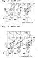
- the temperature measurement is generaffy executed simultaneously at a plurality of locations within the furnace. Accordingly, when the aforementioned fluidic resistance type temperature sensor is employed in a multi-temperature measuring apparatus, it is considered, as shown in Fig. 2, that plural sets of the fluidic resistance type temperature sensors are connectively juxtaposed with each other, with the source S of supply of the working fluid and the pressure control device 40 being commonly used therein. Such construction, however, undesirably produces some new problems different from the aforementioned ones.
- a first problem is that since the environmental temperatures are different from each other at the locations or points where the amplifier supply valves 47, sensitivity set valves 46 and trim valves 43 generating the reference pressure drop are provided, all of which valves are located at the upstream side of each probe, the points to be measured in temperature undergo the influences by the environmental temperatures different from each other. In other words, there occur measurement errors of temperature different from each other at the points to be measured and this fact results in that it is, in fact, impossible to correct the measurement errors.
- a second problem is that it is impossible to supply the working fluid to each probe at the constant pressure. More specifically, the source S of supply of the working fluid and the pressure control device 40 are used commonly and therefore, since the pipings for supplying the working fluid towards each probe 41 therethrough inevitably become long, a pressure fluctuation is produced in the working fluid in the course of the pipings under the influence of the environmental temperature. As a result, this phenomenon causes the large measurement error in temperature.
- a fourth problem is that in the multi-temperature measuring apparatus as shown in Fig. 2 or 3, since a plurality of the temperature sensor units are connectively juxtaposed with each other at the downstream side of the source S of supply of the working fluid, it is necessary to supply the working fluid at the constant pressure towards each unit, thus resulting in that the consumption of the working fluid is undesirably increased proportionately to the increased number of the points to be measured.
- the present invention has been developed with a view to substantially eliminating the above described disadvantages inherent in the prior art method and apparatus for measuring temperature, and has for its essential object to provide an improved method and apparatus for measuring temperature, which is capable of measuring high temperatures without any influence upon a working fluid by the environmental temperature or the temperature of the working fluid.
- Another important object of the present invention is to provide the temperature measuring apparatus of the above described type which is capable of preventing a measurement error through detection of a damage of a temperature sensor.
- a further object of the present invention is to provide the temperature measuring apparatus of the above described type which is capable of sequentially measuring high temperatures, with excellent accuracy, at a plurality of locations, while the working fluid is effectively utilized therein.
- a method of measuring temperature through a state change of a fluid including the steps of supplying a working fluid at a constant mass flow rate into a flow channel thereof defining a throttle position at a temperature-sensitive portion, measuring a pressure difference between opposite ends of the throttle portion, and calculating the temperature from the measured pressure difference.
- a fluidic resistance type temperature measuring apparatus including a source of supply of a working fluid, a probe having an external cylinder closed at its one end and an internal cylinder which is accommodated in the external cylinder and has a capillary tube at its forward end, a supply tube of the working fluid for introducing the working fluid from the source thereof into either the internal cylinder or the external cylinder, a pressure control device and a mass flow control device disposed in series in the course of the supply tube, a differential pressure gauge for detecting a pressure drop across the capillary tube, and a temperature operating means for operating the temperature on the basis of a signal sent from the differential pressure gauge.
- a fluidic resistance type temperature measuring apparatus includes a source of supply of a working fluid, a plurality of probes connectively disposed in series and each having an external cylinder closed at its one end and an internal cylinder which is accommodated in the external cylinder and has a capillary tube at its forward end, a supply tube of the working fluid connected to a first probe to introduce the working fluid from the source thereof into the first probe, a pressure control device and a mass flow control device disposed in series in the course of the supply tube, a plurality of differential pressure gauges disposed correspondingly to respective probes to detect a pressure drop across the capillary tube, and a temperature operating means for operating the temperatures on the basis of signals sent from respective differential pressure gauges.
- a temperature measuring apparatus which is provided with a probe 1 or a temperature sensor as a temperature-sensitive portion, a source S of supply of a working fluid for supplying the working fluid towards the probe 1, and the like.
- the probe 1 is composed of an internal cylinder 4 having, at its forward end, a capillary tube 2 which assumes a form of a throttle portion and an external cylinder 6 having one closed end.
- the probe 1 is set, for example, across a furnace wall F as shown in Fig. 4, to measure a temperature within the furnace.
- the source S of supply of the working fluid is connected with the internal cylinder 4 through a reducing valve 8, a pressure control device 9, a mass flow control device 10 and pipings 7 so that the highly pressurized working fluid may be supplied from the source S thereof into the internal cylinder 4 sequentially through the reducing valve 8, the pressure control device 9 and the mass flow control device 10.
- a first flow channel 3 of the working fluid is defined within the internal cylinder 4 and a second flow channel thereof is formed between the internal cylinder 4 and the external cylinder 6.
- the mass flow control device 10 includes a mass flowmeter 10-1, a valve-opening regulator 10-2 and a valve 10-3 so that the mass flow of the working fluid sequentially supplied from the source S thereof is detected by the mass flowmeter 10-1 to be compared with a predetermined value thereof in the valve-opening regulator 10-2 and thereafter, the regulator 10-2 controls the opening of the valve 10-3 in accordance with the comparison result in order to keep the mass flow rate constant.
- a differential pressure gauge 11 connected with an inlet portion of the internal cylinder 4 and an outlet portion of the external cylinder 6 respectively through pressure detecting tubes 11 a and 11 to detect a pressure drop AP across the capillary tube 2 within the probe 1.
- the differential pressure gauge 11 is further coupled to a temperature operator 12 for operating the temperature in accordance with an output signal from the differential pressure gauge 11, with the temperature operator 12 being also coupled to a temperature indicator 13 for indicating the temperature.
- the temperature within the furnace is measured through detection of the aforementioned pressure drop AP by the differential pressure gauge 11, as will be described in detail hereinbelow.
- a highly pressurized working fluid such as Ar gas or the like is initially supplied from the source S of supply of the working fluid.
- the working fluid supplied from the source S thereof is reduced in pressure down to a predetermined value by the reducing valve 8 and the pressure control device 9 and is then supplied into the first channel 3 i.e., the internal cylinder 4 within the probe 1 at a constant rate Q of the mass flow effected by the mass flow control device 10.
- the working fluid supplied into the probe 1 at the constant mass flow rate Q is discharged to the atmosphere from a discharge port 6a of the external cylinder 6 through the capillary tube 2 of the internal cylinder 4.
- the pressure drop AP arises at the portion of the capillary tube 2 and is calculated as follows with the use of the temperature T within the probe 1, the inner diameter d and the length t of the capillary tube 2 at the temperature T, and the viscosity coefficient u(T) and the density p(T) of the working fluid at the same temperature.
- the following Hagen-Poiseuille equation is established with respect to a volumetric flow rate Qv flowing within the capillary tube 2.
- the following equation (3) is established between the volumetric flow rate Qv and the mass flow rate Q. Accordingly, the equation (1) can be obtained.
- the working fluid may be either a gas or a liquid
- the gas is superior to the liquid in resolving power with respect to temperature, since the former is generally highly dependent upon the temperature as compared with the latter.
- the kinematic viscosity of the liquid decreases, as the temperature rises and on the contrary, the kinematic viscosity of the gas increases, as the temperature rises.
- the relation between the pressure drop AP and the temperature is graphically shown in Fig. 6 in the case where the liquid is employed as the working fluid or in Fig. 7 in the case where the gas is employed as the working fluid.
- the mass flow rate Q of the working fluid is made a parameter on condition that the capillary tube 2 within the probe 1 is made up of tungsten having a thermal expansion coefficient of 20 x 10 -6 /°C and the inner diameter d and the length l thereof are respectively 0.76 mm and 13 mm at a temperature of 0 °C, as shown in Fig. 9, with Ar gas being employed as the working fluid. Since the pressure drop AP becomes more highly dependent upon the temperature, as the mass flow rate Q increases, it appears that the temperature measuring apparatus is improved both in temperature resolving power and in accuracy.
- Fig. 10 shows the temperature measuring apparatus according to a. second embodiment of the present invention, in which the working fluid is supplied into the second channel 5 formed between the internal cylinder 4 and the external cylinder 6 of the probe 1 and is then led into the first channel 3 within the internal cylinder 4 through the capillary tube 2 to be discharged from the probe 1.
- the pressure drop AP across the capillary tube 2 which is an output of the temperature measuring apparatus of the fluidic resistance type, is determined by the temperature of the working fluid in the capillary tube 2, as described hereinabove.
- the temperature measurement is feasible, as long as the measurement is performed with respect to a steady temperature or a gradual change of the temperature, in the case where the working fluid is caused to flow from the internal cylinder 4 towards the external cylinder 6, as shown in Fig. 4, as well as in the case shown in Fig. 10.
- the temperature measuring apparatus of the fluidic resistance type is further provided with a probe damage detecting means 15a which includes a differentiation circuit 16, a comparative operation processing circuit 17a and a warning means 18, all of which are sequentially connected with one another in this order, with the differentiation circuit 16 being also coupled with the differential pressure gauge 11.
- the differentiation circuit 16 differentiates a signal of the pressure drop AP sent from the differential pressure gauge 11 with respect to time, to calculate a fluctuating rate of the pressure drop AP and thereafter, upon comparison of the fluctuating rate with a predetermined reference fluctuating rate by the comparative operation processing circuit 17a, if the pressure drop ⁇ P is abnormal in its fluctuating rate, an abnormal signal is emitted from the comparative operation processing circuit 17a to effect the warning means 18 to emit the warning.
- the pressure drop AP12 produced through the capillary tube 2 of the probe 1 is detected with time lag represented by a time t1 required for the external surface of the external cylinder 6 of the probe 1 to turn from T1 to T2 in temperature, a time t2 required for the internal surface of the external cylinder 6 to become T2 in temperature and a time t3 required for the working fluid to become T2 in temperature.
- the time lags t1 and t3 undergo great influences respectively by components, pressure, flow condition or the like of the atmosphere and by the pressure, flow condition or the like of the working fluid and accordingly, it is actually difficult to forecast or recognize these time lags t1 and t3.
- the time lag t2 can be substantially estimated by the following equation, since a thermal transfer coefficient a and the wall thickness w of the probe 1 are known.
- the fluctuating rate ⁇ P12/dt of the aforementioned pressure drop ⁇ P12 can be expressed by the following equation (7), when the pressure drops corresponding to the temperatures T1 and T2 within the furnace are represented respectively by AP1 and AP2.
- the equation (7) means that the fluctuating rate
- the fluctuating rate (d ⁇ P/dt)max of the pressure drop detected by the temperature measuring apparatus can be expressed as follows.
- the predetermined reference fluctuating rate is represented by in accordance with the aforementioned equation (8) and the output signal from the differential pressure gauge 11 is differentiated with respect to time by the differentiation circuit 16 so that the fluctuating rate d ⁇ P dt dt of the detected pressure drop may be obtained.
- the output signal from the differential pressure gauge 11 is differentiated with respect to time by the differentiation circuit 16 so that the fluctuating rate
- the warning is emitted from the warning means 18.
- the differentiation circuit 16 is coupled to the differential pressure gauge 11 in the temperature measuring apparatus of Fig. 11, the probe damage detecting means 15b may be provided with the differentiation circuit 16 coupled to the temperature operator 12, as shown in Fig. 12. Also, in this case, after the detected pressure drop ⁇ P has been converted into temperature by the temperature operating means 12, the temperature signal is inputted into the differentiation circuit 16 so that a fluctuating rate of the operated temperature may be calculated instead of that of the detected pressure drop AP. Thereafter, upon comparison of the calculated fluctuating rate of the operated temperature with a reference fluctuating rate thereof in the comparative operation processing circuit 17a, the damage of the probe 1 can be readily detected.
- the predetermined reference fluctuating rate is not limited by that described so far on the basis of the measuring apparatus of the present invention, but the fluctuating rate of the pressure drop, temperature or the like corresponding to, for example, a heat curve of a material to be treated may be appropriately selected as the reference fluctuating rate.
- the probe damage detecting means 15c is provided with a mass flowmeter 20 for detecting the mass flow of the working fluid on the discharge side of the working fluid of the probe 1 and the comparative operation processing circuit 17b coupled to both of the mass flowmeter 20 and the aforementioned mass flowmeter 10-1 of the mass flow control device 10, and the damage of the probe 1 is detected through comparison, in the comparative operation processing circuit 17b, between the mass flows of the working fluid on the supply side and on the discharge side of the working fluid of the probe 1 i.e., the flow signal from the mass flow control device 10 and that from the mass flowmeter 20.
- both flow signals are coincident with each other and on the contrary, when the probe 1 has been damaged, they are inevitably discrepant from each other. Accordingly, when the discrepancy has been detected in the comparative operation processing circuit 17b, the abnormal signal is emitted therefrom to cause the warning means 18 to emit the warning.
- the probe damage detecting means comprises a first probe damage detecting portion for detecting the damage of the probe 1 by the change of the fluctuating rate of the pressure drop AP or the temperature and a second probe damage detecting portion for detecting the damage of the probe 1 by the discrepancy between the mass flows.
- the probe damage detecting means 15d having the first probe damage detecting portion i.e., the probe damage detecting means 15a and the second probe damage detecting portion i.e., the probe damage detecting means 15c, wherein a couple of solenoid valves 21 and 22 are disposed respectively on the supply side and on the discharge side of the working fluid of the probe 1 so as to be closed on the occasion of the damage of the probe 1.
- the probe damage detecting means 15a, 15b, 15c and 15d described so far is employed in the temperature measuring apparatus having the probe 1 in which the working fluid flows from the external cylinder 6 towards the inside of the internal cylinder 4, the working fluid may be caused to flow, within the probe 1, from the inside of the internal cylinder 4 towards the external cylinder 6, as shown in Fig. 4 and also in this case, the damage of the probe 1 can be detected by either the abnormal pressure or the abnormal mass flow rate in the same manner as described above.
- Fig. 15 illustrates a multi-temperature measuring apparatus on the basis of the method of measuring temperature according to the present invention.
- the multi-temperature measuring apparatus of Fig. 15 is provided with five probes comprising a first, a second, a third , a fourth and a fifth proves 1-1, 1-2, 1-3, 1-4 and 1-5 as the temperature-sensitive sensors, which probes are connected with one another in series.
- each probe 1-1, 1-2, 1-3 or 1-4 exclusive of the fifth probe 1-5 is connected, at its discharge port 6a of the working fluid which is the outlet portion of the external cylinder 6 of the probe 1-1, 1-2, 1-3 or 1-4, with the supply port 4a of the working fluid of the adjacent probe 1-2, 1-3, 1-4 or 1-5 which port is the inlet portion of the internal cylinder 4 thereof, with the supply port 4a of the working fluid of the first probe 1-1 being coupled to a supply tube or piping 7 for supplying the working fluid therethrough into the first probe 1-1 and the discharge port 6a of the working fluid of the fifth probe 1-5 being open to the atmosphere.
- the working fluid is caused to flow at the constant mass flow rate from the source S of supply of the working fluid towards the internal cylinder 4 of the first probe 1-1 sequentially through the reducing valve 8, the pressure control device 9, the mass flow control device 10 and the supply piping 7 of the working fluid.
- Each one differential pressure gauge 11-1, 11-2, 11-3, 11-4 or 11-5 is coupled to the supply port 4a of the working fluid of the corresponding probe 1-1, 1-2, 1-3, 1-4 or 1-5 and to the discharge port 6a thereof respectively through the pressure detecting tubes 11 a and 11b to directly detect the pressure drop ⁇ P across the capillary tube 2 within each probe 1, with the pressure signals sent from the differential pressure gauges 11-1, 11-2, 11-3, 11-4 and 11-5 being applied to the temperature operating means 12.
- the working fluid for example, Ar gas or the like is initially supplied from the source S of supply of the working fluid.
- the working fluid supplied is not only reduced in pressure down to the predetermined value through the reducing valve 8 but also simultaneously controlled so as to be held at the constant pressure through the pressure control device 9.
- the working fluid is further supplied towards the supply port 4a of the working fluid of the first probe 1-1 at the constant mass flow rate Q through the mass flow control device 10 and thereafter, it passes through the capillary tube 2 to be discharged from the discharge port 6a of the working fluid of the first probe 1-1.
- the pressure drop AP1 arises at the capillary tube 2
- the temperature T1 of the atmosphere at a location where the first probe 1-1 is provided is operated by the temperature operating means 12 in accordance with the detected result.
- the working fluid discharged from the discharge port 6a of the working fluid of the first probe 1-1 is then supplied into the second probe 1-2 from the supply port 4a thereof and passes through the capillary tube 2 within the second probe 1-2 to be discharged from the discharge port 6a thereof.
- the capillary tube 2 within the probe 1-2 produces the pressure drop AP2 and the temperature T2 of the atmosphere at a location where the second probe 1-2 is provided is detected through operation of the pressure drop AP2, in the same way as in case of the first probe 1-1.
- the temperature measurement through detection of the pressure drop at the capillary tube is repeated until the working fluid has passed through the capillary tube 2-5 of the last probe i.e., the fifth probe 1-5 in the arrangement shown in Fig. 15.
- the working fluid passed through each probe 1-1, 1-2, 1-3, 1-4 or 1-5 one by one is finally discharged to the atmosphere from the discharge port 6a of the fifth probe 1-5.
- the pressure drop ⁇ P across the capillary tube 2 depends upon only the temperature of the working fluid at the time when the working fluid passes therethrough, the pressure drop ⁇ P never undergoes any influence by a progress of the temperature or pressure of the working fluid before it enters any one probe, the material, quality of the material or configuration of the probe, the environmental temperature around the material, the atmospheric pressure or the like.
- this fact never exerts any influence upon the pressure drop of the working fluid at the time when it passes through the next probe. Accordingly, not only the correct temperature measurement can be executed, but also a plurality of the temperature measurements corresponding to the number of the probes can be sequentially executed by provision of the needed number of the probes at the locations required for the measurements.
- Fig. 16 there are additionally provided five three-way valves 23, five on-off valves 24-1, 24-2, 24-3, 24-4 and 24-5 and five by-pass valves 25-1, 25-2, 25-3 25-4 and 25-5 including necessary pipings in the multi-temperature measuring apparatus shown in Fig. 15. Even when only the second probe 1-2 has been damaged or intentionally out of use, for example, the temperature measurement can be continued without any influence upon the other probes 1-1, 1-3, 1-4 and 1-5.
- the multi-temperature measuring apparatus shown in Fig. 16 may be further provided with the aforegoing probe damage detecting means 15a, 15b, 15c or 15d for detecting the damage of any probe 1-1, 1-2, 1-3, 1-4 or 1-5.
- the above described on-off valve, the by-pass valve and the three-way valve corresponding to the probe subjected to the damage are operated by the signal sent from the comparative operation processing circuit 17a or 17b.
- the pressure detecting tube 11 b on the low pressure side is connected to the differential pressure gauge 11, it may be open to the atmosphere in the case where the fluctuation of the atmospheric pressure including that caused by any noise is negligibly small or extremely slow in fluctuating rate.
- a resistance means 30 such as a silencer producing a large flow resistance, as shown in Fig. 17, or an accumulator 31 for once accumulating therein the working fluid to be discharged, as shown in Fig. 18.
- a hunting phenomenon hardly takes place with respect to the output from the measuring apparatus.
- the hunting not only it can be physically restricted in a manner as shown in Fig. 17 or 18, but also it may be electrically eliminated in a manner that the electric signal picked up from the differential pressure gauge 11 is caused to pass through a filter circuit.
- the working fluid is supplied at a constant mass flow rate into a flow channel thereof defining a throttle portion at a temperature-sensitive portion and upon measurement of a pressure difference between opposite ends of the throttle portion, the temperature can be recognized through calculation of the measured pressure difference.
- a source of supply of a working fluid a probe having an external cylinder closed at its one end and an internal cylinder which is accommodated in the external cylinder and has a capillary tube at its forward end, a supply piping of the working fluid for introducing the working fluid from the source thereof into either the internal cylinder or the external cylinder, a pressure control device and a mass flow control device disposed in series in the course of the supply piping, a differential pressure gauge for detecting a pressure drop across the capillary tube, and a temperature operating means for operating the temperature on the basis of a signal sent from the differential pressure gauge.
- the present invention provides a fluidic resistance type temperature measuring apparatus including a source of supply of a working fluid, a plurality of probes connectively disposed in series and each having an external cylinder closed at its one end and an internal cylinder which is accommodated in the external cylinder and has a capillary tube at its forward end, a supply piping of the working fluid connected to a first probe to introduce the working fluid from the source thereof into the first probe, a pressure control device and a mass flow control device disposed in series in the course of the supply tube, a plurality of differential pressure gauges disposed correspondingly to respective probes to detect a pressure drop across the capillary tube, and a temperature operating means for operating the temperatures on the basis of signals sent from respective differential pressure gauges.
Landscapes
- Physics & Mathematics (AREA)
- General Physics & Mathematics (AREA)
- Measuring Volume Flow (AREA)
- Measuring Temperature Or Quantity Of Heat (AREA)
Abstract
Description
- The present invention generally relates to a method of measuring temperature and an apparatus employed for effecting said method and more particularly, to a method and an apparatus for measuring temperature, for example, the temperature within a furnace, the temperature of a molten material such as a molten iron or the like by making use of a state change resulting from a temperature change of a fluid.
- Conventionally, a thermocouple, a resistance thermometer or the like has been widely employed for measurement of a high temperature within a boiler, a furnace or the like. However, since these kinds of the thermometers are, in principle, restricted in material of a temperature-sensitive portion exposed to the high temperature, it has been difficult to take any countermeasure against oxidization or other causes shortening the life of the thermometer and accordingly, either of such thermometers is generally improper to be used for a long time.
- Accordingly, there has been developed a temperature measuring apparatus of fluidic resistance type or a fluidic pyrometer which offers an advantage such that a material of a probe i.e., a temperature sensor forming a temperature-sensitive portion can be freely selected in view of its life without any restriction by a measuring principle. As for the principle of the fluidic resistance type temperature measuring apparatus, the temperature is detected through a change of pressure drop of a gas at the time when it passes through a throttle portion such as a capillary tube, by making use of a temperature dependence of a viscosity coefficient of the gas. Fig. 1 illustrates a fundamental construction of the temperature measuring apparatus of the above described type in which a working fluid such as Ar gas or the like is initially supplied from a source S' of supply of the working fluid at a constant pressure through a
pressure control device 40, and the pressure drop AP across thecapillary tube 42 within theprobe 41 which arises correspondingly to the temperature of an atmosphere to be measured is detected as a pressure difference ΔPc between the pressure on the secondary side of atrim valve 43 and the pressure on the secondary side of thecapillary tube 42. Thereafter, upon amplification of the pressure difference ΔPc by afluidic element 44, it is detected as an electric signal by apressure transducer 45. - Such system is substantially similar in construction to a kind of electric circuit called Wheatstone bridge and, a slight fluctuation of the pressure drop at a sensitivity set
valve 46, anamplifier supply valve 47 or thetrim valve 43 exerts a large influence upon the pressure signal from thefluidic element 44. Accordingly, a state change of the working fluid caused by an environmental temperature gives the fluctuation with respect to the pressure drop at each of theaforementioned valves capillary tube 42 within theprobe 41 i.e., a change in temperature detected by theprobe 41, the temperature measuring apparatus of this kind has a disadvantage that it is liable to be subjected to the influence by the environmental temperature. - In addition, in the aforementioned fluidic resistance type temperature measuring apparatus, when the
probe 41 as the temperature-sensitive sensor is damaged, for example, it is cracked or a hole is accidentally made therein, since the working fluid spills out or the atmosphere enters theprobe 41, the signal outputted from thepressure transducer 45 is continuously outputted therefrom in a state where it does not correctly correspond to the temperature to be measured. - The damage of the probe in the fluidic resistance type temperature measuring apparatus is substantially equivalent to a burnout with respect to the thermocouple. However, although no signal is outputted in case of the burnout of the thermocouple, the wrong signal is continuously outputted in the fluidic resistance type temperature measuring apparatus. It is, therefore, difficult to detect the damage of the
probe 41 and, in the case where the temperature is controlled through measurement thereof, for example, by the fluidic resistance type temperature measuring apparatus, the temperature is controlled undesirably to a value different from the predetermined one. This is another shortcoming of the fluidic resistance type temperature measuring apparatus. - On the other hand, in the case where the temperature within the furnace is controlled, the temperature measurement is generaffy executed simultaneously at a plurality of locations within the furnace. Accordingly, when the aforementioned fluidic resistance type temperature sensor is employed in a multi-temperature measuring apparatus, it is considered, as shown in Fig. 2, that plural sets of the fluidic resistance type temperature sensors are connectively juxtaposed with each other, with the source S of supply of the working fluid and the
pressure control device 40 being commonly used therein. Such construction, however, undesirably produces some new problems different from the aforementioned ones. - A first problem is that since the environmental temperatures are different from each other at the locations or points where the
amplifier supply valves 47, sensitivity setvalves 46 andtrim valves 43 generating the reference pressure drop are provided, all of which valves are located at the upstream side of each probe, the points to be measured in temperature undergo the influences by the environmental temperatures different from each other. In other words, there occur measurement errors of temperature different from each other at the points to be measured and this fact results in that it is, in fact, impossible to correct the measurement errors. - A second problem is that it is impossible to supply the working fluid to each probe at the constant pressure. More specifically, the source S of supply of the working fluid and the
pressure control device 40 are used commonly and therefore, since the pipings for supplying the working fluid towards eachprobe 41 therethrough inevitably become long, a pressure fluctuation is produced in the working fluid in the course of the pipings under the influence of the environmental temperature. As a result, this phenomenon causes the large measurement error in temperature. - As shown in Fig. 3, it is possible to supply the working fluid towards each probe at the constant pressure, with the pressure fluctuation in the course of the pipings being restricted by
pressure control devices 40a for correction use additionally provided immediately before each temperature sensor unit. However, since the pressure fluctuation on the primary side of eachpressure control device 40a for correction use is large, the pressure can not be fully controlled thereby. Accordingly, not only the measurement error in temperature undesirably becomes large, but also a plurality of the pressure control devices for correction use are inevitably needed by the number corresponding to that of the points to be measured in temperature and the additional provision of some devices causes the temperature measuring apparatus to be manufactured undesirably at increased cost. This problem is the third one. - A fourth problem is that in the multi-temperature measuring apparatus as shown in Fig. 2 or 3, since a plurality of the temperature sensor units are connectively juxtaposed with each other at the downstream side of the source S of supply of the working fluid, it is necessary to supply the working fluid at the constant pressure towards each unit, thus resulting in that the consumption of the working fluid is undesirably increased proportionately to the increased number of the points to be measured.
- Accordingly, the present invention has been developed with a view to substantially eliminating the above described disadvantages inherent in the prior art method and apparatus for measuring temperature, and has for its essential object to provide an improved method and apparatus for measuring temperature, which is capable of measuring high temperatures without any influence upon a working fluid by the environmental temperature or the temperature of the working fluid.
- Another important object of the present invention is to provide the temperature measuring apparatus of the above described type which is capable of preventing a measurement error through detection of a damage of a temperature sensor.
- A further object of the present invention is to provide the temperature measuring apparatus of the above described type which is capable of sequentially measuring high temperatures, with excellent accuracy, at a plurality of locations, while the working fluid is effectively utilized therein.
- In accomplishing these and other objects, according to one preferred embodiment of the present invention, there is provided a method of measuring temperature through a state change of a fluid, said method including the steps of supplying a working fluid at a constant mass flow rate into a flow channel thereof defining a throttle position at a temperature-sensitive portion, measuring a pressure difference between opposite ends of the throttle portion, and calculating the temperature from the measured pressure difference.
- In another aspect of the present invention, there is provided a fluidic resistance type temperature measuring apparatus including a source of supply of a working fluid, a probe having an external cylinder closed at its one end and an internal cylinder which is accommodated in the external cylinder and has a capillary tube at its forward end, a supply tube of the working fluid for introducing the working fluid from the source thereof into either the internal cylinder or the external cylinder, a pressure control device and a mass flow control device disposed in series in the course of the supply tube, a differential pressure gauge for detecting a pressure drop across the capillary tube, and a temperature operating means for operating the temperature on the basis of a signal sent from the differential pressure gauge.
- In a further aspect of the present invention, a fluidic resistance type temperature measuring apparatus includes a source of supply of a working fluid, a plurality of probes connectively disposed in series and each having an external cylinder closed at its one end and an internal cylinder which is accommodated in the external cylinder and has a capillary tube at its forward end, a supply tube of the working fluid connected to a first probe to introduce the working fluid from the source thereof into the first probe, a pressure control device and a mass flow control device disposed in series in the course of the supply tube, a plurality of differential pressure gauges disposed correspondingly to respective probes to detect a pressure drop across the capillary tube, and a temperature operating means for operating the temperatures on the basis of signals sent from respective differential pressure gauges.
- These and other objects and features of the present invention will become apparent from the following description taken in conjunction with the preferred embodiments thereof with reference to the accompanying drawings, throughout which like parts are designated by like reference numerals, and in which:
- Fig. 1 is a diagrammatic view of a conventional fluidic pyrometer (already referred to);
- Fig. 2 is a schematic view of one example of a multi-temperature measuring apparatus employing therein the fluidic pyrometer of Fig. 1 (already referred to);
- Fig. 3 is a view similar to Fig. 2, which particularly shows another example thereof (already referred to);
- Fig. 4 is a schematic view of a fluidic resistance type temperature measuring apparatus according to a first embodiment of the present invention;
- Fig. 5 is a schematic view of a mass flow control device employed in the temperature measuring apparatus of Fig. 4;
- Fig. 6 is a graph showing a relation between a pressure drop across a capillary tube disposed within a temperature sensor employed in the temperature measuring apparatus of Fig. 4 and a temperature of the working fluid in the case where a liquid is employed as a working'fluid;
- Fig. 7 is a graph similar to that of Fig. 6 in the case where a gas is employed as the working fluid;
- Fig. 8 is a graph similar to that of Fig. 7 in the case where Ar gas is employed as the working fluid, with a mass flow thereof being caused to be a parameter;
- Fig. 9 is a fragmentary sectional view of a probe employed as a temperature sensor, which provides the graph of Fig. 8;
- Fig. 10 is a view similar to Fig. 4, which particularly shows a second embodiment of the present invention;
- Fig. 11 is a schematic view of the fluidic resistance type temperature measuring apparatus of the present invention having a probe damage detecting means;
- Fig. 12 is a view similar to Fig. 11, which particularly shows another example of the probe damage detecting means;
- Fig. 13 is a view similar to Fig. 11, which particularly shows still another example of the probe damage detecting means;
- Fig. 14 is a view similar to Fig. 11, which particularly shows a further example of the probe damage detecting means;
- Fig. 15 is a schematic view of a multi-temperature detecting apparatus employing therein the method of measuring temperature according to the present invention;
- Fig. 16 is a view similar to Fig. 15, which particularly relates to a modification thereof;
- Fig. 17 is a view similar to Fig. 4, which is further provided with a silencer as a fluidic resistance means at the downstream side of the working fluid; and
- Fig. 18 is a view similar to Fig. 17, which is provided with an accumulator in place of the silencer at the downstream side of the working fluid.
- Referring now to the drawings, there is shown in Fig. 4, a temperature measuring apparatus according to a first embodiment of the present invention, which is provided with a
probe 1 or a temperature sensor as a temperature-sensitive portion, a source S of supply of a working fluid for supplying the working fluid towards theprobe 1, and the like. Theprobe 1 is composed of aninternal cylinder 4 having, at its forward end, acapillary tube 2 which assumes a form of a throttle portion and anexternal cylinder 6 having one closed end. Theprobe 1 is set, for example, across a furnace wall F as shown in Fig. 4, to measure a temperature within the furnace. The source S of supply of the working fluid is connected with theinternal cylinder 4 through a reducingvalve 8, apressure control device 9, a massflow control device 10 andpipings 7 so that the highly pressurized working fluid may be supplied from the source S thereof into theinternal cylinder 4 sequentially through the reducingvalve 8, thepressure control device 9 and the massflow control device 10. Afirst flow channel 3 of the working fluid is defined within theinternal cylinder 4 and a second flow channel thereof is formed between theinternal cylinder 4 and theexternal cylinder 6. - As shown in Fig. 5, the mass
flow control device 10 includes a mass flowmeter 10-1, a valve-opening regulator 10-2 and a valve 10-3 so that the mass flow of the working fluid sequentially supplied from the source S thereof is detected by the mass flowmeter 10-1 to be compared with a predetermined value thereof in the valve-opening regulator 10-2 and thereafter, the regulator 10-2 controls the opening of the valve 10-3 in accordance with the comparison result in order to keep the mass flow rate constant. - There is also provided a
differential pressure gauge 11 connected with an inlet portion of theinternal cylinder 4 and an outlet portion of theexternal cylinder 6 respectively throughpressure detecting tubes 11 a and 11 to detect a pressure drop AP across thecapillary tube 2 within theprobe 1. Thedifferential pressure gauge 11 is further coupled to atemperature operator 12 for operating the temperature in accordance with an output signal from thedifferential pressure gauge 11, with thetemperature operator 12 being also coupled to atemperature indicator 13 for indicating the temperature. The temperature within the furnace is measured through detection of the aforementioned pressure drop AP by thedifferential pressure gauge 11, as will be described in detail hereinbelow. - In the next place, a method of measuring temperature will be explained hereinafter with the use of the temperature measuring apparatus having the above described construction.
- A highly pressurized working fluid such as Ar gas or the like is initially supplied from the source S of supply of the working fluid. The working fluid supplied from the source S thereof is reduced in pressure down to a predetermined value by the reducing
valve 8 and thepressure control device 9 and is then supplied into thefirst channel 3 i.e., theinternal cylinder 4 within theprobe 1 at a constant rate Q of the mass flow effected by the massflow control device 10. - . The working fluid supplied into the
probe 1 at the constant mass flow rate Q is discharged to the atmosphere from adischarge port 6a of theexternal cylinder 6 through thecapillary tube 2 of theinternal cylinder 4. At this moment, the pressure drop AP arises at the portion of thecapillary tube 2 and is calculated as follows with the use of the temperature T within theprobe 1, the inner diameter d and the length t of thecapillary tube 2 at the temperature T, and the viscosity coefficient u(T) and the density p(T) of the working fluid at the same temperature.
- More specifically, the following Hagen-Poiseuille equation is established with respect to a volumetric flow rate Qv flowing within the
capillary tube 2.

- Besides, when the kinematic viscosity of the working fluid is represented by y(T),


- Consequently, when a fluid such as Ar gas or the like which is known in state change by temperature is employed as the working fluid, since v(T) is known and the mass flow rate Q is constant, AP is represented as a function of temperature T, thus resulting in that the temperature T can be made known through detection of ΔP i.e., the differential pressure between a pressure P1 within the
first channel 3 and another pressure P2 at thedischarge port 6a of the working fluid by thedifferential pressure gauge 11. A temperature dependence of the kinematic viscosity ν(T) is generally extremely large as compared with a change of the inner diameter or the length of the capillary tube caused by a thermal expansion thereof. Accordingly, there is practically little problem in considering from the equation (5) that AP is substantially dependent upon ν(T). - It is to be noted that although the working fluid may be either a gas or a liquid, the gas is superior to the liquid in resolving power with respect to temperature, since the former is generally highly dependent upon the temperature as compared with the latter. As a rule, the kinematic viscosity of the liquid decreases, as the temperature rises and on the contrary, the kinematic viscosity of the gas increases, as the temperature rises. Accordingly, the relation between the pressure drop AP and the temperature is graphically shown in Fig. 6 in the case where the liquid is employed as the working fluid or in Fig. 7 in the case where the gas is employed as the working fluid. Fig. 8 graphically shows one example of the latter in which the mass flow rate Q of the working fluid is made a parameter on condition that the
capillary tube 2 within theprobe 1 is made up of tungsten having a thermal expansion coefficient of 20 x 10-6/°C and the inner diameter d and the length ℓ thereof are respectively 0.76 mm and 13 mm at a temperature of 0 °C, as shown in Fig. 9, with Ar gas being employed as the working fluid. Since the pressure drop AP becomes more highly dependent upon the temperature, as the mass flow rate Q increases, it appears that the temperature measuring apparatus is improved both in temperature resolving power and in accuracy. However, when the flow exceeds an appropriate amount thereof, the heat transfer within theprobe 1 can not follow the flow and the temperature difference between the fluid and the atmosphere within the furnace becomes large, thus resulting in that the temperature of the atmosphere can not be correctly indicated. Accordingly, since the flow of the working fluid would be inevitably restricted up to its upper limit which largely depends upon the construction, configuration and dimensions of theprobe 1, those of theprobe 1 are required to be determined experimentally. - Fig. 10 shows the temperature measuring apparatus according to a. second embodiment of the present invention, in which the working fluid is supplied into the
second channel 5 formed between theinternal cylinder 4 and theexternal cylinder 6 of theprobe 1 and is then led into thefirst channel 3 within theinternal cylinder 4 through thecapillary tube 2 to be discharged from theprobe 1. The pressure drop AP across thecapillary tube 2 which is an output of the temperature measuring apparatus of the fluidic resistance type, is determined by the temperature of the working fluid in thecapillary tube 2, as described hereinabove. In view of only this fact, if the inside of theprobe 1 decreases in thermal resistance, the temperature measurement is feasible, as long as the measurement is performed with respect to a steady temperature or a gradual change of the temperature, in the case where the working fluid is caused to flow from theinternal cylinder 4 towards theexternal cylinder 6, as shown in Fig. 4, as well as in the case shown in Fig. 10. - In the case shown in Fig. 4, however, since there exists the
second channel 5 i.e., the discharge channel of the working fluid between thefirst channel 3 and theexternal cylinder 6 of theprobe 1, the temperature measuring apparatus of this kind decreases in response characteristic. Accordingly, when there exists a rapid change of the temperature within the furnace, it is to be desired that the working fluid is caused to flow as shown in Fig. 10. - In Fig. 11, the temperature measuring apparatus of the fluidic resistance type is further provided with a probe
damage detecting means 15a which includes adifferentiation circuit 16, a comparativeoperation processing circuit 17a and a warning means 18, all of which are sequentially connected with one another in this order, with thedifferentiation circuit 16 being also coupled with thedifferential pressure gauge 11. Thedifferentiation circuit 16 differentiates a signal of the pressure drop AP sent from thedifferential pressure gauge 11 with respect to time, to calculate a fluctuating rate of the pressure drop AP and thereafter, upon comparison of the fluctuating rate with a predetermined reference fluctuating rate by the comparativeoperation processing circuit 17a, if the pressure drop ΔP is abnormal in its fluctuating rate, an abnormal signal is emitted from the comparativeoperation processing circuit 17a to effect the warning means 18 to emit the warning. - Subsequently, an operating principle of the probe
damage detecting means 15a will be explained hereinbelow by way of example with reference to the temperature measuring apparatus of Fig. 11. - A consideration will be given with respect to a case where the
external cylinder 6 of theprobe 1 has been damaged on condition that the pressure within the furnace is higher than the pressure within theprobe 1. Since the pressure PO within the furnace is higher than the pressure p1 within theprobe 1, a part of the gas which forms the atmosphere within the furnace flows into theprobe 1 and pass through thecapillary tube 2, together with the working fluid. As a result, since the pressure drop ΔP detected by thedifferential pressure gauge 11 instantaneously increases simultaneously with the damage of theprobe 1, the fluctuating rate dΔP/dt
thereof in this event is greater than the fluctuating rate corresponding to the fluctuation of the temperature within the furnace. More specifically, supposing that the temperature within the furnace fluctuates instantaneously from T1 to T2, the pressure drop AP12 produced through thecapillary tube 2 of theprobe 1 is detected with time lag represented by a time t1 required for the external surface of theexternal cylinder 6 of theprobe 1 to turn from T1 to T2 in temperature, a time t2 required for the internal surface of theexternal cylinder 6 to become T2 in temperature and a time t3 required for the working fluid to become T2 in temperature. The time lags t1 and t3 undergo great influences respectively by components, pressure, flow condition or the like of the atmosphere and by the pressure, flow condition or the like of the working fluid and accordingly, it is actually difficult to forecast or recognize these time lags t1 and t3. On the contrary, the time lag t2 can be substantially estimated by the following equation, since a thermal transfer coefficient a and the wall thickness w of theprobe 1 are known. t2 = w/16a ..... (6) - Accordingly, the fluctuating rate ΔP12/dt
of the aforementioned pressure drop ΔP12 can be expressed by the following equation (7), when the pressure drops corresponding to the temperatures T1 and T2 within the furnace are represented respectively by AP1 and AP2.
of the pressure drop detected by thedifferential pressure gauge 11 does not exceed at least
probe 1 has been damaged. - On the other hand, when ΔPmax and APmin respectively represents the pressure drops corresponding to the upper temperature limit Tmax and the lower temperature limit Tmin within the measuring range of temperature detectable by the temperature measuring apparatus of the fluidic resistance type, the fluctuating rate (dΔP/dt)max
of the pressure drop detected by the temperature measuring apparatus can be expressed as follows.

differential pressure gauge 11 is differentiated with respect to time by thedifferentiation circuit 16 so that the fluctuating rate dΔP dt dt
of the detected pressure drop may be obtained. Thereafter, upon comparison of the fluctuating rate of the detected pressure drop with the predetermined reference fluctuating rate in the comparativeoperation processing circuit 17a, when the former is greater than the latter i.e.,
probe 1 has been damaged and the abnormal signal is emitted to cause the warning means to emit the warning. - Conversely, an explanation will be made hereinafter in the case where the pressure P0 within the furnace is lower than the pressure P1 within the
probe 1. - At the same time when the
external cylinder 6 of theprobe 1 has been damaged, a part of the working fluid having entered theprobe 1 flows out therefrom into the furnace. As a result, the pressure drop ΔP detected by thedifferential pressure gauge 11 rapidly decreases simultaneously with the damage of theprobe 1 and the fluctuating rate |dΔP/dt|
of the detected pressure drop in this event is greater than the predetermined reference fluctuating rate as described so far. - In the same manner as described above, the output signal from the
differential pressure gauge 11 is differentiated with respect to time by thedifferentiation circuit 16 so that the fluctuating rate |dΔP/dt| of the detected pressure drop may be obtained and thereafter, upon comparison of the fluctuating rate |dΔP/dt|
with the predetermined reference fluctuating rate
operation processing circuit 17a, if the former is greater than the latter, it is judged that theprobe 1 has been damaged and the abnormal signal is emitted to cause the warning means 18 to emit the warning. - Accordingly, in the case where the following equation is established, the warning is emitted from the warning means 18.

- It is to be noted that although the
differentiation circuit 16 is coupled to thedifferential pressure gauge 11 in the temperature measuring apparatus of Fig. 11, the probedamage detecting means 15b may be provided with thedifferentiation circuit 16 coupled to thetemperature operator 12, as shown in Fig. 12. Also, in this case, after the detected pressure drop ΔP has been converted into temperature by the temperature operating means 12, the temperature signal is inputted into thedifferentiation circuit 16 so that a fluctuating rate of the operated temperature may be calculated instead of that of the detected pressure drop AP. Thereafter, upon comparison of the calculated fluctuating rate of the operated temperature with a reference fluctuating rate thereof in the comparativeoperation processing circuit 17a, the damage of theprobe 1 can be readily detected. - It is also to be noted that the predetermined reference fluctuating rate is not limited by that described so far on the basis of the measuring apparatus of the present invention, but the fluctuating rate of the pressure drop, temperature or the like corresponding to, for example, a heat curve of a material to be treated may be appropriately selected as the reference fluctuating rate.
- Moreover, as shown in Fig. 13, it may be modified such that the probe
damage detecting means 15c is provided with amass flowmeter 20 for detecting the mass flow of the working fluid on the discharge side of the working fluid of theprobe 1 and the comparativeoperation processing circuit 17b coupled to both of themass flowmeter 20 and the aforementioned mass flowmeter 10-1 of the massflow control device 10, and the damage of theprobe 1 is detected through comparison, in the comparativeoperation processing circuit 17b, between the mass flows of the working fluid on the supply side and on the discharge side of the working fluid of theprobe 1 i.e., the flow signal from the massflow control device 10 and that from themass flowmeter 20. In other words, when theprobe 1 is in order, both flow signals are coincident with each other and on the contrary, when theprobe 1 has been damaged, they are inevitably discrepant from each other. Accordingly, when the discrepancy has been detected in the comparativeoperation processing circuit 17b, the abnormal signal is emitted therefrom to cause the warning means 18 to emit the warning. - In addition, it may be further modified such that the probe damage detecting means comprises a first probe damage detecting portion for detecting the damage of the
probe 1 by the change of the fluctuating rate of the pressure drop AP or the temperature and a second probe damage detecting portion for detecting the damage of theprobe 1 by the discrepancy between the mass flows. There is shown in Fig. 14, one example of the probedamage detecting means 15d having the first probe damage detecting portion i.e., the probe damage detecting means 15a and the second probe damage detecting portion i.e., the probedamage detecting means 15c, wherein a couple ofsolenoid valves probe 1 so as to be closed on the occasion of the damage of theprobe 1. - It should be noted that although either of the probe
damage detecting means probe 1 in which the working fluid flows from theexternal cylinder 6 towards the inside of theinternal cylinder 4, the working fluid may be caused to flow, within theprobe 1, from the inside of theinternal cylinder 4 towards theexternal cylinder 6, as shown in Fig. 4 and also in this case, the damage of theprobe 1 can be detected by either the abnormal pressure or the abnormal mass flow rate in the same manner as described above. - Fig. 15 illustrates a multi-temperature measuring apparatus on the basis of the method of measuring temperature according to the present invention.
- The multi-temperature measuring apparatus of Fig. 15 is provided with five probes comprising a first, a second, a third , a fourth and a fifth proves 1-1, 1-2, 1-3, 1-4 and 1-5 as the temperature-sensitive sensors, which probes are connected with one another in series. More specifically, each probe 1-1, 1-2, 1-3 or 1-4 exclusive of the fifth probe 1-5 is connected, at its
discharge port 6a of the working fluid which is the outlet portion of theexternal cylinder 6 of the probe 1-1, 1-2, 1-3 or 1-4, with thesupply port 4a of the working fluid of the adjacent probe 1-2, 1-3, 1-4 or 1-5 which port is the inlet portion of theinternal cylinder 4 thereof, with thesupply port 4a of the working fluid of the first probe 1-1 being coupled to a supply tube or piping 7 for supplying the working fluid therethrough into the first probe 1-1 and thedischarge port 6a of the working fluid of the fifth probe 1-5 being open to the atmosphere. By the aforementioned arrangement, the working fluid is caused to flow at the constant mass flow rate from the source S of supply of the working fluid towards theinternal cylinder 4 of the first probe 1-1 sequentially through the reducingvalve 8, thepressure control device 9, the massflow control device 10 and thesupply piping 7 of the working fluid. Each one differential pressure gauge 11-1, 11-2, 11-3, 11-4 or 11-5 is coupled to thesupply port 4a of the working fluid of the corresponding probe 1-1, 1-2, 1-3, 1-4 or 1-5 and to thedischarge port 6a thereof respectively through the pressure detecting tubes 11 a and 11b to directly detect the pressure drop ΔP across thecapillary tube 2 within eachprobe 1, with the pressure signals sent from the differential pressure gauges 11-1, 11-2, 11-3, 11-4 and 11-5 being applied to the temperature operating means 12. - The temperature measurement by the apparatus having the above described construction will be explained hereinafter.
- The working fluid, for example, Ar gas or the like is initially supplied from the source S of supply of the working fluid. The working fluid supplied is not only reduced in pressure down to the predetermined value through the reducing
valve 8 but also simultaneously controlled so as to be held at the constant pressure through thepressure control device 9. In this state, the working fluid is further supplied towards thesupply port 4a of the working fluid of the first probe 1-1 at the constant mass flow rate Q through the massflow control device 10 and thereafter, it passes through thecapillary tube 2 to be discharged from thedischarge port 6a of the working fluid of the first probe 1-1. - In this event, since the pressure drop AP1 arises at the
capillary tube 2, upon detection of the pressure drop AP1 by the differential pressure gauge 11-1, the temperature T1 of the atmosphere at a location where the first probe 1-1 is provided is operated by the temperature operating means 12 in accordance with the detected result. The working fluid discharged from thedischarge port 6a of the working fluid of the first probe 1-1 is then supplied into the second probe 1-2 from thesupply port 4a thereof and passes through thecapillary tube 2 within the second probe 1-2 to be discharged from thedischarge port 6a thereof. Also in this event, thecapillary tube 2 within the probe 1-2 produces the pressure drop AP2 and the temperature T2 of the atmosphere at a location where the second probe 1-2 is provided is detected through operation of the pressure drop AP2, in the same way as in case of the first probe 1-1. - Henceforth, The temperature measurement through detection of the pressure drop at the capillary tube is repeated until the working fluid has passed through the capillary tube 2-5 of the last probe i.e., the fifth probe 1-5 in the arrangement shown in Fig. 15. The working fluid passed through each probe 1-1, 1-2, 1-3, 1-4 or 1-5 one by one is finally discharged to the atmosphere from the
discharge port 6a of the fifth probe 1-5. - As described so far, according to the construction of the multi-temperature measuring apparatus of the present invention, since the pressure drop ΔP across the
capillary tube 2 depends upon only the temperature of the working fluid at the time when the working fluid passes therethrough, the pressure drop ΔP never undergoes any influence by a progress of the temperature or pressure of the working fluid before it enters any one probe, the material, quality of the material or configuration of the probe, the environmental temperature around the material, the atmospheric pressure or the like. In other words, even if the working fluid has passed through a plurality of probes previously, this fact never exerts any influence upon the pressure drop of the working fluid at the time when it passes through the next probe. Accordingly, not only the correct temperature measurement can be executed, but also a plurality of the temperature measurements corresponding to the number of the probes can be sequentially executed by provision of the needed number of the probes at the locations required for the measurements. - In Fig. 16, there are additionally provided five three-
way valves 23, five on-off valves 24-1, 24-2, 24-3, 24-4 and 24-5 and five by-pass valves 25-1, 25-2, 25-3 25-4 and 25-5 including necessary pipings in the multi-temperature measuring apparatus shown in Fig. 15. Even when only the second probe 1-2 has been damaged or intentionally out of use, for example, the temperature measurement can be continued without any influence upon the other probes 1-1, 1-3, 1-4 and 1-5. - It is to be noted that the multi-temperature measuring apparatus shown in Fig. 16 may be further provided with the aforegoing probe
damage detecting means operation processing circuit - It is also to be noted that in either of the embodiments described so far, the pressure detecting tube 11 b on the low pressure side is connected to the
differential pressure gauge 11, it may be open to the atmosphere in the case where the fluctuation of the atmospheric pressure including that caused by any noise is negligibly small or extremely slow in fluctuating rate. - It is further to be noted that there may be provided a resistance means 30 such as a silencer producing a large flow resistance, as shown in Fig. 17, or an
accumulator 31 for once accumulating therein the working fluid to be discharged, as shown in Fig. 18. In either of these two cases in contrast with the aforementioned case, even when the atmospheric pressure violently fluctuates, a hunting phenomenon hardly takes place with respect to the output from the measuring apparatus. As for the hunting, not only it can be physically restricted in a manner as shown in Fig. 17 or 18, but also it may be electrically eliminated in a manner that the electric signal picked up from thedifferential pressure gauge 11 is caused to pass through a filter circuit. - As clearly shown in the description made so far, according to the method of the present invention, the working fluid is supplied at a constant mass flow rate into a flow channel thereof defining a throttle portion at a temperature-sensitive portion and upon measurement of a pressure difference between opposite ends of the throttle portion, the temperature can be recognized through calculation of the measured pressure difference.
- Furthermore, according to the temperature measuring apparatus of the present invention employed for effecting the aforementioned method, there are provided a source of supply of a working fluid, a probe having an external cylinder closed at its one end and an internal cylinder which is accommodated in the external cylinder and has a capillary tube at its forward end, a supply piping of the working fluid for introducing the working fluid from the source thereof into either the internal cylinder or the external cylinder, a pressure control device and a mass flow control device disposed in series in the course of the supply piping, a differential pressure gauge for detecting a pressure drop across the capillary tube, and a temperature operating means for operating the temperature on the basis of a signal sent from the differential pressure gauge.
- Consequently, by making use of the method and apparatus of the present invention, it is possible to achieve the temperature measurement with high reliability even at a high temperature in a range from 1500 to 3000 °C, without any influence by the environmental temperature or the temperature of the working fluid, notwithstanding the apparatus is simple in construction.
- Besides, when a probe damage detecting means for detecting the damage of the probe is additionally provided, since the damage of the probe can be readily detected, an erroneous measurement can be advantageously prevented.
- In addition, the present invention provides a fluidic resistance type temperature measuring apparatus including a source of supply of a working fluid, a plurality of probes connectively disposed in series and each having an external cylinder closed at its one end and an internal cylinder which is accommodated in the external cylinder and has a capillary tube at its forward end, a supply piping of the working fluid connected to a first probe to introduce the working fluid from the source thereof into the first probe, a pressure control device and a mass flow control device disposed in series in the course of the supply tube, a plurality of differential pressure gauges disposed correspondingly to respective probes to detect a pressure drop across the capillary tube, and a temperature operating means for operating the temperatures on the basis of signals sent from respective differential pressure gauges.
- As a result, since the working fluid supplied into each probe flows at a constant mass flow rate at all times, sequential temperature measurements can be executed with excellent accuracy at a plurality of locations which are high in temperature, with the working fluid being effectively utilized.
- Although the present invention has been fully described by way of examples with reference to the accompanying drawings, it is to be noted here that various changes and modifications will be apparent to those skilled in the art. Therefore, unless otherwise such changes and modifications depart from the scope of the present invention, they should be construed as being included therein.
Claims (11)
Applications Claiming Priority (8)
| Application Number | Priority Date | Filing Date | Title |
|---|---|---|---|
| JP7602386A JPS62232527A (en) | 1986-04-01 | 1986-04-01 | Method and apparatus for measuring temperature |
| JP76023/86 | 1986-04-01 | ||
| JP61157697A JPH073369B2 (en) | 1986-07-03 | 1986-07-03 | Fluid resistance type temperature measuring device |
| JP157697/86 | 1986-07-03 | ||
| JP30992686A JPH0629796B2 (en) | 1986-12-27 | 1986-12-27 | Fluid resistance type temperature measuring device |
| JP309927/86 | 1986-12-27 | ||
| JP30992786A JPH0629797B2 (en) | 1986-12-27 | 1986-12-27 | Multi-point temperature measuring device with fluid resistance thermometer |
| JP309926/86 | 1986-12-27 |
Publications (3)
| Publication Number | Publication Date |
|---|---|
| EP0243701A2 true EP0243701A2 (en) | 1987-11-04 |
| EP0243701A3 EP0243701A3 (en) | 1989-05-24 |
| EP0243701B1 EP0243701B1 (en) | 1993-07-28 |
Family
ID=27465897
Family Applications (1)
| Application Number | Title | Priority Date | Filing Date |
|---|---|---|---|
| EP87104764A Expired - Lifetime EP0243701B1 (en) | 1986-04-01 | 1987-03-31 | Apparatus for measuring temperature |
Country Status (3)
| Country | Link |
|---|---|
| US (1) | US4881185A (en) |
| EP (1) | EP0243701B1 (en) |
| DE (1) | DE3786696D1 (en) |
Cited By (1)
| Publication number | Priority date | Publication date | Assignee | Title |
|---|---|---|---|---|
| US20130308677A1 (en) * | 2010-12-20 | 2013-11-21 | Canon Kabushiki Kaisha | Temperature measuring apparatus and method for a fluid in a micro channel |
Families Citing this family (12)
| Publication number | Priority date | Publication date | Assignee | Title |
|---|---|---|---|---|
| DE4004552C2 (en) * | 1989-02-14 | 1994-07-07 | Mitsubishi Electric Corp | Signal processing method for a thermal flow sensor |
| ATE95305T1 (en) * | 1989-04-03 | 1993-10-15 | Landis & Gyr Business Support | FLOW AND/OR HEAT MEASURING DEVICE. |
| SE9600334D0 (en) * | 1996-01-30 | 1996-01-30 | Radi Medical Systems | Combined flow, pressure and temperature sensor |
| JP3915209B2 (en) * | 1997-12-03 | 2007-05-16 | 住友電気工業株式会社 | Brake fluid temperature detection method and brake fluid pressure control method |
| FR2818746B1 (en) * | 2000-12-26 | 2003-03-28 | Gaz De France | METHOD AND DEVICE FOR EVALUATING THE WOBBE INDEX OF A COMBUSTIBLE GAS |
| US6679625B2 (en) * | 2001-12-17 | 2004-01-20 | International Business Machines Corporation | Scanning heat flow probe |
| US9687603B2 (en) | 2010-04-16 | 2017-06-27 | Medtronic, Inc. | Volume monitoring for implantable fluid delivery devices |
| US20110257907A1 (en) * | 2010-04-16 | 2011-10-20 | Medtronic, Inc. | Pressure-based temperature estimation for implantable fluid delivery devices |
| US8810394B2 (en) | 2010-04-16 | 2014-08-19 | Medtronic, Inc. | Reservoir monitoring for implantable fluid delivery devices |
| CN106768091B (en) * | 2017-03-20 | 2023-09-22 | 西华大学 | A water flow and temperature measurement device for generating unit efficiency testing |
| CN106872059A (en) * | 2017-04-12 | 2017-06-20 | 山东电力设备有限公司 | A kind of oil-filled transformer measurement device of oil tempera and measuring method |
| CN114082059B (en) * | 2021-12-24 | 2024-03-19 | 河北谊安奥美医疗设备有限公司 | Automatic calibration device and method for anesthesia machine |
Family Cites Families (8)
| Publication number | Priority date | Publication date | Assignee | Title |
|---|---|---|---|---|
| US4349282A (en) * | 1977-02-08 | 1982-09-14 | Spill-Fire Alarm Systems Ltd. | Transducers |
| GB1504244A (en) * | 1977-03-18 | 1978-03-15 | Normalair Garrett Ltd | Laminar flow temperature sensors |
| US4244231A (en) * | 1979-03-05 | 1981-01-13 | Teterevyatnikov Lev N | Method for measuring mass flow of a substance |
| US4264423A (en) * | 1979-09-17 | 1981-04-28 | The United States Of America As Represented By The Secretary Of The Army | Fluidic thermistor/fugacity device |
| US4491924A (en) * | 1982-04-22 | 1985-01-01 | The Babcock & Wilcox Company | Olefin oxidation reactor temperature control |
| JPS59206737A (en) * | 1983-05-11 | 1984-11-22 | Cosmo Keiki:Kk | Leakage testing device having temperature compensating function |
| US4604902A (en) * | 1984-10-24 | 1986-08-12 | Geoscience Ltd | Means and techniques useful in mass flowmeters for multiphase flows |
| US4659235A (en) * | 1985-04-16 | 1987-04-21 | Borg-Warner Automotive, Inc. | Fluid pressure sensor with temperature indication |
-
1987
- 1987-03-27 US US07/030,606 patent/US4881185A/en not_active Expired - Fee Related
- 1987-03-31 DE DE8787104764T patent/DE3786696D1/en not_active Expired - Lifetime
- 1987-03-31 EP EP87104764A patent/EP0243701B1/en not_active Expired - Lifetime
Cited By (1)
| Publication number | Priority date | Publication date | Assignee | Title |
|---|---|---|---|---|
| US20130308677A1 (en) * | 2010-12-20 | 2013-11-21 | Canon Kabushiki Kaisha | Temperature measuring apparatus and method for a fluid in a micro channel |
Also Published As
| Publication number | Publication date |
|---|---|
| DE3786696D1 (en) | 1993-09-02 |
| EP0243701B1 (en) | 1993-07-28 |
| US4881185A (en) | 1989-11-14 |
| EP0243701A3 (en) | 1989-05-24 |
Similar Documents
| Publication | Publication Date | Title |
|---|---|---|
| EP0243701B1 (en) | Apparatus for measuring temperature | |
| US5837903A (en) | Device for measuring exhaust flowrate using laminar flow element | |
| US8290721B2 (en) | Flow measurement diagnostics | |
| US4953388A (en) | Air gauge sensor | |
| JP4020433B2 (en) | Transmitter with average pitot tube type primary element and method of use thereof | |
| EP2805136B1 (en) | System for monitoring flow through mass flow controllers in real time | |
| US4675834A (en) | Pressure variation detecting type leakage inspection system with temperature compensation | |
| RU2276397C2 (en) | Self-centering magnetic assembly for device for measuring linear displacement | |
| US6012474A (en) | Mass flow control method and device utilizing a sonic nozzle | |
| US20030192595A1 (en) | Flow control valve with integral sensor and controller and related method | |
| US4651559A (en) | Method and apparatus for detecting leaks in a gas pipe line | |
| US6834542B2 (en) | Method for determining the atmospheric pressure on the basis of the pressure in the intake line of an internal combustion engine | |
| EP3320408A1 (en) | Method and apparatus for gas flow control | |
| US7201067B2 (en) | System and method for determining flow characteristics | |
| US4735100A (en) | Fluid flow sensor having multiplying effect | |
| US6917886B2 (en) | Microflow based differential pressure sensor | |
| US7096723B2 (en) | Method and device for determining the throughput of a flowing medium | |
| US7530274B2 (en) | Apparatus for providing an output proportional to pressure divided by temperature (P/T) | |
| US5668313A (en) | Method for correcting the output signal of an air mass meter | |
| US20250053182A1 (en) | Method and Apparatus for Automatic Self Calibration of Mass Flow Controller | |
| JP2005267572A (en) | An abnormality determination method and apparatus for flow control | |
| JPS63167230A (en) | Liquid resistance type temperature measuring instrument | |
| JPH0629797B2 (en) | Multi-point temperature measuring device with fluid resistance thermometer | |
| JPS6312929A (en) | Fluid resistance type temperature measuring instrument | |
| Rivetti et al. | Metrological performances of Venturi flowmeters in normal, supercritical and superfluid helium |
Legal Events
| Date | Code | Title | Description |
|---|---|---|---|
| PUAI | Public reference made under article 153(3) epc to a published international application that has entered the european phase |
Free format text: ORIGINAL CODE: 0009012 |
|
| AK | Designated contracting states |
Kind code of ref document: A2 Designated state(s): DE FR GB |
|
| PUAL | Search report despatched |
Free format text: ORIGINAL CODE: 0009013 |
|
| AK | Designated contracting states |
Kind code of ref document: A3 Designated state(s): DE FR GB |
|
| 17P | Request for examination filed |
Effective date: 19890919 |
|
| 17Q | First examination report despatched |
Effective date: 19901129 |
|
| GRAA | (expected) grant |
Free format text: ORIGINAL CODE: 0009210 |
|
| AK | Designated contracting states |
Kind code of ref document: B1 Designated state(s): DE FR GB |
|
| PG25 | Lapsed in a contracting state [announced via postgrant information from national office to epo] |
Ref country code: DE Effective date: 19930728 |
|
| REF | Corresponds to: |
Ref document number: 3786696 Country of ref document: DE Date of ref document: 19930902 |
|
| ET | Fr: translation filed | ||
| PG25 | Lapsed in a contracting state [announced via postgrant information from national office to epo] |
Ref country code: GB Effective date: 19940331 |
|
| PLBE | No opposition filed within time limit |
Free format text: ORIGINAL CODE: 0009261 |
|
| STAA | Information on the status of an ep patent application or granted ep patent |
Free format text: STATUS: NO OPPOSITION FILED WITHIN TIME LIMIT |
|
| 26N | No opposition filed | ||
| GBPC | Gb: european patent ceased through non-payment of renewal fee |
Effective date: 19940331 |
|
| PGFP | Annual fee paid to national office [announced via postgrant information from national office to epo] |
Ref country code: FR Payment date: 20020319 Year of fee payment: 16 |
|
| PG25 | Lapsed in a contracting state [announced via postgrant information from national office to epo] |
Ref country code: FR Free format text: LAPSE BECAUSE OF NON-PAYMENT OF DUE FEES Effective date: 20031127 |
|
| REG | Reference to a national code |
Ref country code: FR Ref legal event code: ST |