EP0243683B1 - Internal combustion engine provided with a pair of rotary eccentric masses arranged to dynamically balance the engine - Google Patents
Internal combustion engine provided with a pair of rotary eccentric masses arranged to dynamically balance the engine Download PDFInfo
- Publication number
- EP0243683B1 EP0243683B1 EP87104459A EP87104459A EP0243683B1 EP 0243683 B1 EP0243683 B1 EP 0243683B1 EP 87104459 A EP87104459 A EP 87104459A EP 87104459 A EP87104459 A EP 87104459A EP 0243683 B1 EP0243683 B1 EP 0243683B1
- Authority
- EP
- European Patent Office
- Prior art keywords
- engine
- crankcase
- casing
- masses
- pair
- Prior art date
- Legal status (The legal status is an assumption and is not a legal conclusion. Google has not performed a legal analysis and makes no representation as to the accuracy of the status listed.)
- Expired - Lifetime
Links
Images
Classifications
-
- F—MECHANICAL ENGINEERING; LIGHTING; HEATING; WEAPONS; BLASTING
- F16—ENGINEERING ELEMENTS AND UNITS; GENERAL MEASURES FOR PRODUCING AND MAINTAINING EFFECTIVE FUNCTIONING OF MACHINES OR INSTALLATIONS; THERMAL INSULATION IN GENERAL
- F16F—SPRINGS; SHOCK-ABSORBERS; MEANS FOR DAMPING VIBRATION
- F16F15/00—Suppression of vibrations in systems; Means or arrangements for avoiding or reducing out-of-balance forces, e.g. due to motion
- F16F15/22—Compensation of inertia forces
- F16F15/26—Compensation of inertia forces of crankshaft systems using solid masses, other than the ordinary pistons, moving with the system, i.e. masses connected through a kinematic mechanism or gear system
- F16F15/264—Rotating balancer shafts
- F16F15/265—Arrangement of two or more balancer shafts
-
- F—MECHANICAL ENGINEERING; LIGHTING; HEATING; WEAPONS; BLASTING
- F02—COMBUSTION ENGINES; HOT-GAS OR COMBUSTION-PRODUCT ENGINE PLANTS
- F02B—INTERNAL-COMBUSTION PISTON ENGINES; COMBUSTION ENGINES IN GENERAL
- F02B67/00—Engines characterised by the arrangement of auxiliary apparatus not being otherwise provided for, e.g. the apparatus having different functions; Driving auxiliary apparatus from engines, not otherwise provided for
Definitions
- This invention relates to an internal combustion engine comprising a crankcase supporting the mobile members and at least one pair of rotary eccentric masses arranged to dynamically balance the engine.
- balancing is effected by rotary eccentric masses which have their axes parallel to the axis of the engine crankshaft and are disposed on opposite sides of this latter.
- Each mass has substantially the shape of a portion of a cylinder bounded by a diametrical plane of the cylinder, and is supported by end bearings housed in seats provided in suitable cylindrical cavities formed in the engine crankcase.
- Each mass is rotated by a transmission driven by the crankshaft and normally consisting of a toothed belt and a corresponding pulley torsionally rigid with the mass itself.
- Each transmission belt is disposed in a plane orthogonal to the crankshaft axis and is normally arranged to drive other engine devices such as the water pump and alternator.
- each of the rotary masses is provided at said drive pulley with a further rolling-contact bearing which is normally housed in a seat provided in a plate fixed to the front wall of the engine crankcase.
- crankcase is very complicated because of the presence of the cavities for housing the rotary masses. This is because each of these cavities is formed in correspondence with one of the side walls of the crankcase and is of large axial length and rather small diameter. The result is that the operations involved in casting crankcases of such a shape are complicated and require special care and caution.
- crankcases are rather wide and heavy because of the presence of the said cavities, each of which is bounded by a wall formed integrally with a corresponding side wall of the crankcase and projects laterally to a considerable extent from said wall.
- the presence of these further walls obviously increases the overall dimensions and weight of the crankcase.
- ducts and conduits of various types have to be provided in the walls of the crankcase or at least connected to this latter.
- Such a lubrication circuit makes the crankcase more complicated and considerably increases its cost.
- the object of the present invention is to provide an internal combustion engine of the initially indicated type which is free from the described drawbacks and allows an easy and rapid removal of the masses form the crankcase.
- an internal combustion engine comprising a crankcase supporting the mobile members, and at least one pair of rotary eccentric masses arranged to dynamically balance said engine, said masses being rotated by a transmission driven by the crankshaft of said engine, each one of said masses being rotatably mounted on a support element connected to said crankcase by removable connection means, characterised in that said support element comprises a tubular casing connected to a side wall of said crankcase, and at least one pair of said casing and arranged to support rotatably the corresponding eccentric mass.
- Each mass 2 is rotatably mounted on a support element, indicated overall by 5, which is connected to a side wall 6 of the crankcase 1 by removable connection means, indicated overall by 7.
- the support element 5 comprises a tubular casing 8 and at least one pair of rolling-contact and/or sliding bearings (Figure 2), each of which is housed in a corresponding side 10 of the casing and is arranged to support a cylindrical end portion 11 of one of the masses 2.
- Each support element also comprises a pair of covers 12 and 13, the first of which closes one end of the casing 8, and the second closes the other end and is provided with a hole 14 to be traversed by a shaft 15, which projects axially from one of the masses 2 as can be clearly seen in Figure 2.
- connection means 7 comprise screws 18 and 19 (Figure 1), each of which is arranged to traverse a corresponding bore in the casing 8 and to screw into a threaded bore 20 in one of the side walls 6 of the crankcase.
- said bores are provided in parts 21 of the casing 8 which project radially from the outer surface of the casing, as can be dearly seen in Figure 3. These parts are suitably strengthened by ribs 22.
- Each of the crankcase side walls 6 comprises a cavity 23 ( Figure 1) arranged to at least partially house a corresponding casing 8.
- the cavity 23 is also bounded by a portion of a cylindrical surface.
- each of the drive shafts 15 with which each mass 2 is provided is chosen so that its end 24 extends beyond the surface 25 which frontally delimits the front wall 26 of the crankcase. This end is supported by a rolling-contact bearing 27 housed in a corresponding seat of a plate 28 which rests on the surface 25 and is fixed by screws 29 to the wall 26.
- a pulley 30 for rotating the corresponding eccentric mass is fixed to the end 24 of the shaft 15 and is driven by a toothed belt 31.
- Each described support element forms substantially a seal between the cavity 32 defined within said element and the external environment. This can be attained by suitable gasket elements, not shown.
- the cavity 32 can be filled with grease in a quantity sufficient to ensure effective lubrication of the bearings 9 for a very long period of time, substantially corresponding to the operational life of the engine.
- the toothed belt 31 rotates the pulleys 30 and consequently the eccentric masses 2, which dynamically balance the engine.
- the pull of the belt is supported by the bearings 27, and thus only a moment is transmitted to the shaft 15, to rotate the eccentric masses.
- crankcase 1 of the described engine is of fairly simple shape, because in contrast to engines of the prior art it does not itself comprise the axial cavities necessary for housing the rotary masses 2, but instead these cavities are provided within support elements 5 completely separate from the crankcase itself.
- the result is that the operations involved in casting such a crankcase are much simpler and less costly.
- the width and the weight of the engine can be reduced with respect to the described conventional engines because of the very small thickness with which the casings 8 can be constructed. In this respect, these can be constructed of materials different from those with which the crankcase is constructed, and can be formed by different mechanical processes.
- the masses 2 can be removed from the crankcase simply and rapidly. In this respect, it is necessary only to separate the transmission belt 31 from the pulleys 30 and remove these from the corresponding shafts 15. Each support element 5 with the relative eccentric mass 2 mounted on it can then be separated from the crankcase by simply unscrewing the screws 18 and 19 which fix each of the casings 8 to the crankcase.
Landscapes
- Engineering & Computer Science (AREA)
- General Engineering & Computer Science (AREA)
- Physics & Mathematics (AREA)
- Acoustics & Sound (AREA)
- Aviation & Aerospace Engineering (AREA)
- Mechanical Engineering (AREA)
- Cylinder Crankcases Of Internal Combustion Engines (AREA)
Description
- This invention relates to an internal combustion engine comprising a crankcase supporting the mobile members and at least one pair of rotary eccentric masses arranged to dynamically balance the engine.
- In engines of this type, balancing is effected by rotary eccentric masses which have their axes parallel to the axis of the engine crankshaft and are disposed on opposite sides of this latter. Each mass has substantially the shape of a portion of a cylinder bounded by a diametrical plane of the cylinder, and is supported by end bearings housed in seats provided in suitable cylindrical cavities formed in the engine crankcase. Each mass is rotated by a transmission driven by the crankshaft and normally consisting of a toothed belt and a corresponding pulley torsionally rigid with the mass itself.
- Each transmission belt is disposed in a plane orthogonal to the crankshaft axis and is normally arranged to drive other engine devices such as the water pump and alternator. In order to support the pull of this belt, each of the rotary masses is provided at said drive pulley with a further rolling-contact bearing which is normally housed in a seat provided in a plate fixed to the front wall of the engine crankcase.
- Certain drawbacks are present in engines of this briefly described type.
- Firstly, the shape of the crankcase is very complicated because of the presence of the cavities for housing the rotary masses. This is because each of these cavities is formed in correspondence with one of the side walls of the crankcase and is of large axial length and rather small diameter. The result is that the operations involved in casting crankcases of such a shape are complicated and require special care and caution.
- Moreover, such crankcases are rather wide and heavy because of the presence of the said cavities, each of which is bounded by a wall formed integrally with a corresponding side wall of the crankcase and projects laterally to a considerable extent from said wall. The presence of these further walls obviously increases the overall dimensions and weight of the crankcase. Again, in order to provide adequate lubrication of the rolling-contact and/or sliding bearings which support each of the rotary masses, ducts and conduits of various types have to be provided in the walls of the crankcase or at least connected to this latter. Such a lubrication circuit makes the crankcase more complicated and considerably increases its cost.
- Finally, the operations required for demounting one of said masses from the relative cavity provided in the crankcase are complicated and require special care and caution. In this respect, in order to demount each of said masses it is firstly necessary to separate from the crankcase some of those parts fixed to its front wall in order to gain access to said cavities. This is done by firstly removing the transmission belt, then the drive pulley for the eccentric masses, and finally the plate housing the first mass support bearing which is located in immediate proximity to said pulley and is arranged to support the width of the belt.
- There is also known form the GB-
A 2 138 890 an internal combustion engine, wherein the dynamical balance is effected by a pair of rotary eccentric masses carried by a pair of shafts rotated by means of a belt drive provided at the flywheel end of the crankshaft. Each one of said shafts is mounted on a first bearing located between a removable cover and the side wall of the crankcase and on a second bearing located in a wall part of the clutching casing. This engine thus presents the drawback of requiring complicated demounting operations, including the access into the crankcase. - The object of the present invention is to provide an internal combustion engine of the initially indicated type which is free from the described drawbacks and allows an easy and rapid removal of the masses form the crankcase.
- This object is attained by an internal combustion engine comprising a crankcase supporting the mobile members, and at least one pair of rotary eccentric masses arranged to dynamically balance said engine, said masses being rotated by a transmission driven by the crankshaft of said engine, each one of said masses being rotatably mounted on a support element connected to said crankcase by removable connection means, characterised in that said support element comprises a tubular casing connected to a side wall of said crankcase, and at least one pair of said casing and arranged to support rotatably the corresponding eccentric mass.
- The present invention will be more apparent from the detailed description thereof given hereinafter by way of example with reference to the accompanying drawings, in which:
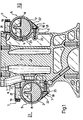
- Figure 1 is a vertical section through the engine of the present invention;
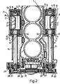
- Figure 2 is a further section through the engine of the preceding figure taken on the line 11-II;
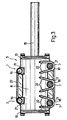
- Figure 3 is a partly sectional side view of a support unit of one of the rotary eccentric masses with which the engine is provided. The engine comprises a crankcase 1, which supports the mobile members, and at least one pair of rotary
eccentric masses 2 arranged to dynamically balance the engine. As can be seen in Figure 1, these are conveniently in the shape of a portion of a cylinder bounded by a diametricalflat surface 3, and comprise a central stiffening rib 4. Their axis is parallel to the crankshaft axis and they lie on one and the other side of the crankshaft, as can be clearly seen in Figure 1. - Each
mass 2 is rotatably mounted on a support element, indicated overall by 5, which is connected to aside wall 6 of the crankcase 1 by removable connection means, indicated overall by 7. - Conveniently, the
support element 5 comprises atubular casing 8 and at least one pair of rolling-contact and/or sliding bearings (Figure 2), each of which is housed in acorresponding side 10 of the casing and is arranged to support acylindrical end portion 11 of one of themasses 2. Each support element also comprises a pair ofcovers casing 8, and the second closes the other end and is provided with ahole 14 to be traversed by ashaft 15, which projects axially from one of themasses 2 as can be clearly seen in Figure 2. - The connection means 7 comprise
screws 18 and 19 (Figure 1), each of which is arranged to traverse a corresponding bore in thecasing 8 and to screw into a threadedbore 20 in one of theside walls 6 of the crankcase. Conveniently, said bores are provided inparts 21 of thecasing 8 which project radially from the outer surface of the casing, as can be dearly seen in Figure 3. These parts are suitably strengthened byribs 22. - Each of the
crankcase side walls 6 comprises a cavity 23 (Figure 1) arranged to at least partially house acorresponding casing 8. In the illustrated embodiment, in which the outer surface of the casing is cylindrical, thecavity 23 is also bounded by a portion of a cylindrical surface. - The axial length of each of the
drive shafts 15 with which eachmass 2 is provided is chosen so that itsend 24 extends beyond the surface 25 which frontally delimits thefront wall 26 of the crankcase. This end is supported by a rolling-contact bearing 27 housed in a corresponding seat of aplate 28 which rests on the surface 25 and is fixed byscrews 29 to thewall 26. Apulley 30 for rotating the corresponding eccentric mass is fixed to theend 24 of theshaft 15 and is driven by atoothed belt 31. - Each described support element forms substantially a seal between the
cavity 32 defined within said element and the external environment. This can be attained by suitable gasket elements, not shown. In this manner, as an alternative to the use of sealed and thus self-lubricated bearings, thecavity 32 can be filled with grease in a quantity sufficient to ensure effective lubrication of thebearings 9 for a very long period of time, substantially corresponding to the operational life of the engine. - During engine operation, the
toothed belt 31 rotates thepulleys 30 and consequently theeccentric masses 2, which dynamically balance the engine. The pull of the belt is supported by thebearings 27, and thus only a moment is transmitted to theshaft 15, to rotate the eccentric masses. - It is therefore apparent that the crankcase 1 of the described engine is of fairly simple shape, because in contrast to engines of the prior art it does not itself comprise the axial cavities necessary for housing the
rotary masses 2, but instead these cavities are provided withinsupport elements 5 completely separate from the crankcase itself. The result is that the operations involved in casting such a crankcase are much simpler and less costly. Moreover, the width and the weight of the engine can be reduced with respect to the described conventional engines because of the very small thickness with which thecasings 8 can be constructed. In this respect, these can be constructed of materials different from those with which the crankcase is constructed, and can be formed by different mechanical processes. Moreover, by using sealed self-lubricating rolling-contact bearings or by filling the casings with a quantity of grease sufficient to ensure effective lubrication of the bearings for the entire life of the engine, lubrication devices are not required and thus ducts to not need to be provided in the crankcase for this purpose or suitable conduits arranged. - Finally, the
masses 2 can be removed from the crankcase simply and rapidly. In this respect, it is necessary only to separate thetransmission belt 31 from thepulleys 30 and remove these from thecorresponding shafts 15. Eachsupport element 5 with the relativeeccentric mass 2 mounted on it can then be separated from the crankcase by simply unscrewing thescrews casings 8 to the crankcase. - It is apparent that modifications can be made to the shape and arrangement of the various described engine parts, but without leaving the scope of the invention.
Claims (10)
Applications Claiming Priority (2)
| Application Number | Priority Date | Filing Date | Title |
|---|---|---|---|
| IT6730986 | 1986-04-15 | ||
| IT67309/86A IT1187984B (en) | 1986-04-15 | 1986-04-15 | INTERNAL COMBUSTION ENGINE PROVIDED WITH A COUPLE OF ROTATING ECCENTRIC MASSES SUITABLE TO NAMICALLY BALANCE THE ENGINE ITSELF |
Publications (2)
| Publication Number | Publication Date |
|---|---|
| EP0243683A1 EP0243683A1 (en) | 1987-11-04 |
| EP0243683B1 true EP0243683B1 (en) | 1990-05-23 |
Family
ID=11301341
Family Applications (1)
| Application Number | Title | Priority Date | Filing Date |
|---|---|---|---|
| EP87104459A Expired - Lifetime EP0243683B1 (en) | 1986-04-15 | 1987-03-26 | Internal combustion engine provided with a pair of rotary eccentric masses arranged to dynamically balance the engine |
Country Status (4)
| Country | Link |
|---|---|
| EP (1) | EP0243683B1 (en) |
| DE (1) | DE3762911D1 (en) |
| ES (1) | ES2014446B3 (en) |
| IT (1) | IT1187984B (en) |
Families Citing this family (7)
| Publication number | Priority date | Publication date | Assignee | Title |
|---|---|---|---|---|
| JPH01250641A (en) * | 1988-02-25 | 1989-10-05 | Volkswagen Ag <Vw> | Mass balancer |
| CA2316152C (en) | 1999-09-03 | 2004-10-05 | Honda Giken Kogyo Kabushiki Kaisha | Balance shaft for engine balancing systems |
| GB0106855D0 (en) * | 2001-03-20 | 2001-05-09 | Perkins Engines Co Ltd | Drive for one or more engine accessories |
| ES2337106T3 (en) † | 2005-10-13 | 2010-04-20 | Schaeffler Kg | RADIAL BEARING PROVISION. |
| DE102006033416A1 (en) | 2006-07-19 | 2008-01-24 | Schaeffler Kg | wave |
| DE102007017873A1 (en) | 2007-04-13 | 2008-10-16 | Schaeffler Kg | Mass balancing transmission of an internal combustion engine |
| DE102009020134A1 (en) * | 2009-05-06 | 2010-11-11 | Schaeffler Technologies Gmbh & Co. Kg | Mass balancing transmission of an internal combustion engine |
Family Cites Families (3)
| Publication number | Priority date | Publication date | Assignee | Title |
|---|---|---|---|---|
| US1433821A (en) * | 1919-09-18 | 1922-10-31 | Clarence E Hull | Crank case for internal-combustion engines |
| DE3119362C2 (en) * | 1981-05-15 | 1985-02-21 | Daimler-Benz Ag, 7000 Stuttgart | Four-cylinder internal combustion engine with a second-order mass balance |
| DE3314801C2 (en) * | 1983-04-23 | 1986-02-20 | Daimler-Benz Ag, 7000 Stuttgart | Arrangement and mounting of balance shafts arranged on both side walls of a crankcase of a four-cylinder internal combustion engine to compensate for inertial forces of the 2nd order |
-
1986
- 1986-04-15 IT IT67309/86A patent/IT1187984B/en active
-
1987
- 1987-03-26 DE DE8787104459T patent/DE3762911D1/en not_active Expired - Lifetime
- 1987-03-26 EP EP87104459A patent/EP0243683B1/en not_active Expired - Lifetime
- 1987-03-26 ES ES87104459T patent/ES2014446B3/en not_active Expired - Lifetime
Also Published As
| Publication number | Publication date |
|---|---|
| DE3762911D1 (en) | 1990-06-28 |
| IT8667309A0 (en) | 1986-04-15 |
| IT1187984B (en) | 1987-12-23 |
| EP0243683A1 (en) | 1987-11-04 |
| ES2014446B3 (en) | 1990-07-16 |
Similar Documents
| Publication | Publication Date | Title |
|---|---|---|
| US5791309A (en) | Balancer shaft supporting structure in engine | |
| US2914963A (en) | Balancing mechanism for multi-cylinder piston engines | |
| US4523553A (en) | Combustion engine with balancing device | |
| US4028963A (en) | Engine balancer | |
| US4125036A (en) | Apparatus for driving engine balancers | |
| JPS5810120A (en) | By-driving device for internal combustion engine | |
| EP0243683B1 (en) | Internal combustion engine provided with a pair of rotary eccentric masses arranged to dynamically balance the engine | |
| JPH11141618A (en) | Engine balancer device | |
| KR930002692A (en) | Horizontal rotator with internal lubricant pump | |
| US2857535A (en) | Adjustable weight vibratory motor | |
| JP3371892B2 (en) | Balancer device for internal combustion engine | |
| JP2000104790A (en) | Engine balancer lubrication structure | |
| JPH01250641A (en) | Mass balancer | |
| KR100356694B1 (en) | Anti-aeration device of oil for the balance shaft of a three-cylindered engine | |
| KR100440023B1 (en) | Balance shaft apparatus | |
| JPH05231479A (en) | Engine balancer | |
| JPH0240344Y2 (en) | ||
| JPS622250Y2 (en) | ||
| GB2299624A (en) | I.c.engine balancer shaft | |
| EP0231157B1 (en) | Two-cylinder engine with a device for balancing the alternating inertia forces | |
| JPH09125981A (en) | Direct-coupled assembly of internal combustion engine and driven machinery | |
| JPH0631197Y2 (en) | Shaft support structure for water pump | |
| JPS6211161B2 (en) | ||
| JPH0724566Y2 (en) | Engine oil pump device | |
| JPS6128783A (en) | Compressor with rotary piston |
Legal Events
| Date | Code | Title | Description |
|---|---|---|---|
| PUAI | Public reference made under article 153(3) epc to a published international application that has entered the european phase |
Free format text: ORIGINAL CODE: 0009012 |
|
| AK | Designated contracting states |
Kind code of ref document: A1 Designated state(s): BE DE ES FR GB NL |
|
| 17P | Request for examination filed |
Effective date: 19880421 |
|
| 17Q | First examination report despatched |
Effective date: 19890220 |
|
| GRAA | (expected) grant |
Free format text: ORIGINAL CODE: 0009210 |
|
| AK | Designated contracting states |
Kind code of ref document: B1 Designated state(s): BE DE ES FR GB NL |
|
| REF | Corresponds to: |
Ref document number: 3762911 Country of ref document: DE Date of ref document: 19900628 |
|
| ET | Fr: translation filed | ||
| PGFP | Annual fee paid to national office [announced via postgrant information from national office to epo] |
Ref country code: BE Payment date: 19910305 Year of fee payment: 5 |
|
| PGFP | Annual fee paid to national office [announced via postgrant information from national office to epo] |
Ref country code: ES Payment date: 19910320 Year of fee payment: 5 |
|
| PLBE | No opposition filed within time limit |
Free format text: ORIGINAL CODE: 0009261 |
|
| STAA | Information on the status of an ep patent application or granted ep patent |
Free format text: STATUS: NO OPPOSITION FILED WITHIN TIME LIMIT |
|
| PGFP | Annual fee paid to national office [announced via postgrant information from national office to epo] |
Ref country code: GB Payment date: 19910322 Year of fee payment: 5 |
|
| PGFP | Annual fee paid to national office [announced via postgrant information from national office to epo] |
Ref country code: FR Payment date: 19910328 Year of fee payment: 5 |
|
| PGFP | Annual fee paid to national office [announced via postgrant information from national office to epo] |
Ref country code: NL Payment date: 19910331 Year of fee payment: 5 |
|
| PGFP | Annual fee paid to national office [announced via postgrant information from national office to epo] |
Ref country code: DE Payment date: 19910429 Year of fee payment: 5 |
|
| 26N | No opposition filed | ||
| PG25 | Lapsed in a contracting state [announced via postgrant information from national office to epo] |
Ref country code: GB Effective date: 19920326 |
|
| PG25 | Lapsed in a contracting state [announced via postgrant information from national office to epo] |
Ref country code: ES Free format text: LAPSE BECAUSE OF NON-PAYMENT OF DUE FEES Effective date: 19920327 |
|
| PG25 | Lapsed in a contracting state [announced via postgrant information from national office to epo] |
Ref country code: BE Effective date: 19920331 |
|
| BERE | Be: lapsed |
Owner name: IVECO FIAT S.P.A. Effective date: 19920331 |
|
| PG25 | Lapsed in a contracting state [announced via postgrant information from national office to epo] |
Ref country code: NL Effective date: 19921001 |
|
| NLV4 | Nl: lapsed or anulled due to non-payment of the annual fee | ||
| GBPC | Gb: european patent ceased through non-payment of renewal fee | ||
| PG25 | Lapsed in a contracting state [announced via postgrant information from national office to epo] |
Ref country code: FR Effective date: 19921130 |
|
| PG25 | Lapsed in a contracting state [announced via postgrant information from national office to epo] |
Ref country code: DE Effective date: 19921201 |
|
| REG | Reference to a national code |
Ref country code: FR Ref legal event code: ST |
|
| REG | Reference to a national code |
Ref country code: ES Ref legal event code: FD2A Effective date: 19990301 |