EP0243682B2 - Control of an agitator mill - Google Patents
Control of an agitator mill Download PDFInfo
- Publication number
- EP0243682B2 EP0243682B2 EP87104450A EP87104450A EP0243682B2 EP 0243682 B2 EP0243682 B2 EP 0243682B2 EP 87104450 A EP87104450 A EP 87104450A EP 87104450 A EP87104450 A EP 87104450A EP 0243682 B2 EP0243682 B2 EP 0243682B2
- Authority
- EP
- European Patent Office
- Prior art keywords
- grinding
- chamber
- auxiliary
- stock
- bodies
- Prior art date
- Legal status (The legal status is an assumption and is not a legal conclusion. Google has not performed a legal analysis and makes no representation as to the accuracy of the status listed.)
- Expired - Lifetime
Links
- 238000001816 cooling Methods 0.000 claims description 39
- 238000009826 distribution Methods 0.000 claims description 18
- 230000001105 regulatory effect Effects 0.000 claims description 16
- 238000009827 uniform distribution Methods 0.000 claims description 11
- 238000004458 analytical method Methods 0.000 claims description 2
- 230000002285 radioactive effect Effects 0.000 claims description 2
- 239000002826 coolant Substances 0.000 claims 11
- 239000000725 suspension Substances 0.000 claims 3
- 230000003247 decreasing effect Effects 0.000 claims 1
- 239000000498 cooling water Substances 0.000 description 42
- 239000000463 material Substances 0.000 description 32
- 238000010586 diagram Methods 0.000 description 7
- 238000003756 stirring Methods 0.000 description 5
- 238000005259 measurement Methods 0.000 description 4
- 238000001514 detection method Methods 0.000 description 3
- 238000010438 heat treatment Methods 0.000 description 3
- 238000000034 method Methods 0.000 description 3
- 230000005484 gravity Effects 0.000 description 2
- 239000000654 additive Substances 0.000 description 1
- 230000004323 axial length Effects 0.000 description 1
- 238000003889 chemical engineering Methods 0.000 description 1
- 230000001276 controlling effect Effects 0.000 description 1
- 238000013461 design Methods 0.000 description 1
- 239000002270 dispersing agent Substances 0.000 description 1
- 238000005516 engineering process Methods 0.000 description 1
- 230000001771 impaired effect Effects 0.000 description 1
- 238000011835 investigation Methods 0.000 description 1
- 238000010327 methods by industry Methods 0.000 description 1
- 239000002245 particle Substances 0.000 description 1
- 238000005192 partition Methods 0.000 description 1
- 230000000717 retained effect Effects 0.000 description 1
- 238000000926 separation method Methods 0.000 description 1
- 238000000935 solvent evaporation Methods 0.000 description 1
- 239000003381 stabilizer Substances 0.000 description 1
- 239000000126 substance Substances 0.000 description 1
- 239000013077 target material Substances 0.000 description 1
- 238000012546 transfer Methods 0.000 description 1
- 230000001960 triggered effect Effects 0.000 description 1
- 238000002604 ultrasonography Methods 0.000 description 1
- 238000011144 upstream manufacturing Methods 0.000 description 1
Images


Classifications
-
- B—PERFORMING OPERATIONS; TRANSPORTING
- B02—CRUSHING, PULVERISING, OR DISINTEGRATING; PREPARATORY TREATMENT OF GRAIN FOR MILLING
- B02C—CRUSHING, PULVERISING, OR DISINTEGRATING IN GENERAL; MILLING GRAIN
- B02C17/00—Disintegrating by tumbling mills, i.e. mills having a container charged with the material to be disintegrated with or without special disintegrating members such as pebbles or balls
- B02C17/16—Mills in which a fixed container houses stirring means tumbling the charge
-
- B—PERFORMING OPERATIONS; TRANSPORTING
- B02—CRUSHING, PULVERISING, OR DISINTEGRATING; PREPARATORY TREATMENT OF GRAIN FOR MILLING
- B02C—CRUSHING, PULVERISING, OR DISINTEGRATING IN GENERAL; MILLING GRAIN
- B02C25/00—Control arrangements specially adapted for crushing or disintegrating
Definitions
- the invention relates to a control device for an agitator mill according to the preamble of patent claim 1.
- the invention is based on the object, based on the knowledge in the publication by Stehr and Schwedes, according to which ground material processed on an agitator mill has constant fineness of fineness, if the specific energy input is kept constant, to create a regulation for an agitator mill in which one constant grind fineness is achieved under largely all operating conditions.
- the invention is based on the further knowledge that keeping the specific energy input constant only leads to a constant fineness of the grinding material in the grinding process if the grinding aid body distribution in the grinding chamber is largely uniform.
- the invention in its most general form therefore creates a regulation which, on the one hand, ensures that the specific energy input is kept constant and, on the other hand, that the distribution of the auxiliary grinding bodies in the grinding chamber is uniform.
- Claim 1 also gives two alternatives of a device for detecting the distribution of the auxiliary grinding bodies over the grinding chamber.
- the first alternative is based on the knowledge that a concentration of auxiliary grinding media in front of the regrind inlet or in front of the separating device leads to an increase in the pressure drop when flowing through the grinding chamber. It also specifies how excessive concentrations of auxiliary grinding bodies are corrected at the two ends of the grinding chamber.
- the second alternative is based on the knowledge that the excessive concentration of auxiliary grinding media in front of the regrind inlet or in front of the separating device leads to an increase in the power introduced into this area, which is essentially converted into heat and is dissipated via an associated separate cooling circuit. A comparison of at least two separate cooling circuits assigned to the two end regions of the grinding chamber or the heat flows transmitted by them thus provides information about the distribution of the auxiliary grinding bodies in the grinding chamber.
- the claim 2 indicates as a device for detecting the distribution of the auxiliary grinding bodies in the grinding chamber that an X-ray or ultrasound or radioactive measuring device is provided for this.
- a sound analysis device is provided as a device for detecting the distribution of the auxiliary grinding bodies in the grinding chamber, since the frequency and strength of the noise generated in the grinding chamber depend on the respective local concentration of auxiliary grinding bodies.
- the regrind mass flow is preferably measured directly, i.e. it is preferred not to carry out an - otherwise conventional per se - indirect measurement via the measurement of the volume flow, but rather the mass flow, i.e. the mass supplied to the grinding chamber per unit of time.
- Appropriate measuring devices are commercially available.
- claims 4 and 5 indicate how excessive concentrations of auxiliary grinding bodies are corrected at the two ends of the grinding chamber.
- Claims 6 to 10 indicate which controlled variable is to be changed if a deviation from the predetermined constant value of the specific energy input into the regrind occurs. If the specific energy input can no longer be regulated constantly, the measures according to claim 11 provide a remedy.
- control according to the invention is not limited to vertical agitator mills; it can also be used for horizontal agitator mills.
- An excessive concentration of grinding aids can likewise occur there in front of the separating device; An excessive concentration of auxiliary grinding media at the regrind inlet is not possible there.
- the agitator mill shown in the drawing has in the usual way a stand 1, on the top of which a projecting support arm 2 is attached, to which in turn a cylindrical grinding container 3 is attached.
- an electric agitator motor 4 is accommodated, which is provided with a V-belt pulley 5, of which a V-belt pulley 8, which is non-rotatably connected to an agitator 7, can be driven in rotation by means of the V-belt 6.
- the vertically arranged grinding container 3 consists of a cylindrical inner cylinder 10 which surrounds a grinding chamber 9 and at the same time forms the grinding container wall and which is also surrounded by a substantially cylindrical cooling jacket 11.
- the lower end of the grinding chamber 9 and the cooling jacket 11 is provided by a base plate 12 which is attached to the inner cylinder 10 and the cooling jacket 11, for example by screwing.
- a grist feed connection 13 is attached, through which ground material can be pumped into the grinding chamber 9 from below.
- An upper cooling water inlet connector 14 and a lower cooling water outlet connector 15 are provided on the cooling jacket 11.
- a drain port 16 for auxiliary grinding bodies is also provided.
- the grinding container 3 has an upper annular flange 17, by means of which it is attached to a cover 18 closing the grinding chamber 9.
- This cover 18 is attached to the underside of a support housing 19, which is attached with its upper end to the support arm 2 of the agitator mill.
- an essential part of the agitator 7 agitator shaft 20 is overhung in the usual way in bearings 21, as is known for example from DE-A-26 29 251 (corresponding to US-A-4 129 261).
- the agitator shaft 20 is passed through the cover 18 in a sealed manner, also known from the document mentioned.
- the agitator 7 has, in a manner known from the publication mentioned, on the agitator shaft 20, disks 23, of which agitator rods 24 project radially as agitator tools.
- counter-rods 25 are axially offset against the stirring rods 24.
- a grinding material outlet nozzle 26 is provided, which is preceded by a so-called annular gap separating device 27 by means of which the auxiliary grinding bodies 28 are retained in the grinding chamber 9.
- Such a separation device 27 is also known from the mentioned publication.
- the agitator 7 can be cooled.
- a cooling water connection 29 and a cooling water outlet 30 are provided in a known manner at the end of the agitator shaft 20 assigned to the V-belt pulley 8.
- the base plate 12 can also be designed to be cool, that is to say hollow, and can be provided with a cooling water inflow 31 and a cooling water outflow 32.
- the detailed structure of the agitator mill is of no importance for the invention; So any kind of stirring tools can be used.
- the cover 18 can also be designed to be coolable. Likewise, the specific design of the separating device is not important in this context.
- the grinding chamber 9 is filled 50 to 90% with auxiliary grinding bodies 28 which have a diameter in the range from 0.3 to 10 mm.
- a first circuit diagram is explained below with reference to FIG. 2.
- Solid lines are generally drawn with solid lines, while dashed lines show control lines which lead from a central computer 33 to different locations where an operation controlled by the computer is to be triggered.
- the power supply to the agitator motor 4 takes place via a frequency converter 34 controlled by the computer 33, so that sensitive speed control of the motor 4 and thus of the agitator 7 is possible.
- the power consumption of the agitator motor 4 is recorded at a measuring point 35.
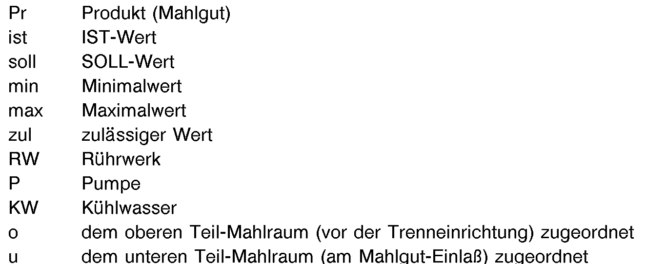
- code letters are attached, which have the following meaning for all measuring points still to be mentioned:
- the millbase is fed in by means of a millbase pump 36 via a millbase feed line 37 to the millbase feed pipe 13 of the grinding container 3.
- the pump 36 is driven by an electric pump motor 38, the power supply of which is provided by a frequency converter 39, so that the speed of the pump motor 38 and thus the delivery rate of the pump 36 can be controlled very precisely.
- This frequency converter is also controlled by the computer 33.
- the pump motor 38 is assigned a measuring point 40 for detecting the electrical power consumed. Furthermore, a measuring point 41 is assigned for the detection of the pump motor or pump speed
- the regrind feed line 37 there are also a measuring point 42 for detecting the temperature of the material to be supplied, a measuring point 43 for detecting the regrind mass flow conveyed by the regrind pump and a measuring point 44 for detecting the regrind pressure in front of or at the entrance the grinding room 9.
- a measuring point 45 is assigned to the grist outlet port 26 for detecting the temperature of the emerging ground grist.
- the agitator shaft 20 is assigned a measuring point 46 for detecting the speed of the agitator shaft 20.
- the cooling water supply takes place via a central cooling water line 47, in which a shut-off valve 48 which can be controlled by the computer 33 is arranged and to which a proportional valve 49 which is also controlled by the computer 33 is arranged, the shut-off behavior of which is therefore proportional to the degree of opening or closing.
- a shut-off valve 48 which can be controlled by the computer 33 is arranged and to which a proportional valve 49 which is also controlled by the computer 33 is arranged, the shut-off behavior of which is therefore proportional to the degree of opening or closing.
- Such commercially available valves are particularly well suited for volume flow control, in the present case for cooling water flow control.
- a measuring point 52 for detecting the cooling water flow temperature and a measuring point 53 for detecting the volume flow of the cooling water flow are arranged in line 47.
- the cooling water flowing through the valve 49 and the measuring points 52, 53 is divided into a plurality of cooling water supply branch lines 54, 55, 56.
- the branch line 54 leads to the cooling water connection 29 Agitator shaft 20, the branch line 55 leads to the cooling water inlet connection 14 of the cooling jacket 11 and the branch line 56 leads to the cooling water inflow 31 of the bottom 12 of the grinding container 3.
- the return cooling water coming from the stirring shaft flows through a cooling water return partial line 57 to a cooling water return -Collecting line 58.
- the distribution of the cooling water supply to the three branch lines 54, 55, 56 is carried out by means of manually adjustable valves 62, 63, 64 in these branch lines 54, 55, 56.
- proportional valves controlled by the computer can of course also be provided, so that an individual control of the cooling water partial volume flows is possible.
- a device 66 for supplying grinding auxiliary bodies 28 is also provided, which can also be controlled by the computer 33.
- Such devices are known, for example, from DE-C-20 51 003.
- the supply of grinding auxiliary bodies 28 by means of this device 66 takes place in the regrind feed line 37 immediately before the regrind supply connection 13.
- the inner cylinder 10 and the cooling jacket 11 form a cooling space 11 'which extends essentially over the full axial length of the grinding chamber 9, in the embodiment according to FIG. 3 this cooling space is approximately in the axial center dividing a partition 67 so that two partial cooling spaces 11'a and 11'b are formed.
- the one partial cooling space 11'a is assigned to the partial grinding space 9a, which adjoins the grinding material feed connector 13.
- the other partial cooling space 11'b is assigned to the partial grinding space 9b, which is located in front of the separating device 27, that is to say in front of the grinding material outlet nozzle 26.
- the same reference numerals are used as in FIG. 2, and a renewed description is dispensed with.
- Corresponding cooling water pre-branch lines 54a and 54b are provided for supplying the two partial cooling rooms 11'a and 11'b, which branch off from the cooling water supply line 47.
- Manually adjustable valves 63a and 63b are also provided in both branch lines 54a and 54b.
- proportional valves controlled by the computer can be provided instead of the manually adjustable valves 63a and 63b.
- Cooling water return partial lines 59a and 59b lead from the partial cooling rooms 11'a and 11'b to the cooling water return collecting line 58.
- measuring points 68a and 68b for measuring the cooling water volume flow, ie for measuring the amount of cooling water per unit time in the respective branch line 54a and 54b.
- Measuring points 69a and 69b for measuring the temperature of the corresponding return cooling water are arranged in the two cooling water return sub-lines 59a and 59b.
- volume flow and outlet temperature of the cooling water in the two partial cooling rooms 11'a and 11'b can be determined, which are assigned to the lower grinding chamber half 9a and the upper grinding chamber half 9b.
- the lower grinding chamber half 9a can also be assigned, as a partial cooling chamber, the coolable base plate 12 with a corresponding cooling water supply provided with measuring points in the manner described.
- the mode of operation is as follows:
- the basic requirement is that the specific energy input into the regrind, i.e. the quotient of the power introduced into the millbase by the agitator 7 and the mass flow of the millbase, i.e. the regrind mass fed to the grinding chamber 9 per unit of time, taking into account an allowable deviation, should be kept constant.
- the value of the specific energy input for the specific grinding case is determined empirically in a laboratory or pilot plant under similar conditions on a reduced scale.
- Such an agitator mill for determining such a value should therefore have a similarly designed grinding container and a similarly permitted agitator, including similar agitating tools.
- Control variables for the specific energy input are, on the one hand, the power input into the ground material in the grinding chamber 9 and the ground material mass flow.
- the manipulated variables for this are in turn the power consumption of the agitator motor 4, namely the active power consumption minus an idle power of the motor 4 and agitator mill to be empirically recorded and stored in the computer 32 (without filling of the grinding aid body).
- the speed of the agitator 7 and / or the degree of filling with which the grinding chamber 9 is filled with grinding auxiliary bodies 28 serves as a manipulated variable for the power input into the process space.
- the speed of the Agitator 7 is set via the frequency converter 34.
- the degree of filling of the grinding media is changed by the device 66 for supplying auxiliary grinding media 28, both of which can be controlled by the computer 33.
- An essential overriding variable is the target temperature of the millbase at the outlet 26. If the maximum permissible millbase temperature is exceeded, damage to the millbase can occur. For example, the desired coloristic properties can be impaired, dangerous solvent evaporation can occur, and chemical additives such as dispersants and stabilizers can be thermally degraded. For this reason, the regulation of the power consumption and / or of the ground material mass flow to keep the mass-specific energy supply constant can only be changed in each case taking into account a maximum permissible temperature of the ground material, which is recorded at the measuring point 45. This maximum permissible temperature is one permissible temperature deviation above the target temperature.
- the manipulated variable for controlling a constant regrind outlet temperature is the volume flow of the cooling water. This is set in accordance with the ground material outlet temperature measured at the measuring point 45 - controlled by the computer 33 - by means of a position of the proportional valve 49.
- the division into the individual branch lines 54, 55, 56 takes place via a manual basic setting of the valves 62, 63, 64. If the valve 49 is already fully open, a reduction in the regrind outlet temperature can only be achieved by reducing the power input via the Agitator 7 can be achieved with a corresponding reduction in the ground material mass flow.
- the speed of the agitator 7 can be regulated to change the power input into the regrind within a speed control range around the target speed.
- This speed control range is, for example, in a range of 10% around the target speed.
- the actual speed of the agitator 7 is passed from the measuring point 46 to the computer 33.
- the ground material mass flow is limited by a maximum power consumption and a maximum speed of the pump motor 38 and by a maximum permissible pressure.
- the power consumption is recorded by the measuring point 40 and sent to the computer. Since the speed of the pump motor 38 or the regrind pump 36 detected at the measuring point 41 gives only an indirect indication of the regrind mass flow and since excessive back pressure, air inclusions and other interferences can impair the delivery of the regrind pump 36, the actual mass flow at the measuring point 43 is recorded and transferred to the computer.
- a uniform distribution of the grinding media in the grinding chamber 9 is detected by detecting the grinding material pressure at the measuring point 44 directly in front of the grinding chamber. Since the ground material behind the separating device 27 is subject to atmospheric pressure, the ground material pressure detected at the measuring point 44 reflects the pressure loss in the grinding chamber 9. With a uniform distribution of the auxiliary grinding bodies 28 in the grinding chamber, a target material pressure is given. Exceeding this target pressure beyond a permissible deviation indicates that an excessive grinding media concentration has occurred either at the grinding material inlet, that is to say at the bottom of the grinding chamber 9, or in the region of the grinding material outlet in front of the separating device 27.
- a uniform grinding media distribution in the grinding chamber 9 is present when the forces acting on the auxiliary grinding media 28, namely the force of gravity, the buoyancy and flow forces, are in equilibrium. If gravity predominates, there will be an excessive concentration of grinding media at the bottom of the grinding chamber. If the buoyancy and flow forces predominate, excessive concentration occurs in front of the separator. In both cases there is an increased pressure drop in the grinding chamber, i.e. the grist pressure detected at measuring point 44 increases. Furthermore, the power loss which is merely converted into grinding power for stirring the concentrated grinding auxiliary bodies 28, i.e. An excessive concentration of the auxiliary grinding bodies 28 in the region of the grinding material inlet or in front of the separating device 27 leads to increased heating of the grinding material and to greatly increased wear of the auxiliary grinding bodies 28, the stirring tools and the grinding chamber boundary walls.
- a statement on the question of whether the cause of a pressure increase is a concentration of auxiliary grinding bodies 28 at the bottom of the grinding chamber 9 or in front of the separating device 27 can essentially be derived from the “history”) of the pressure increase. If with an increase in the regrind mass flow by a corresponding increase in the speed of the regrind pump 36, the regrind pressure at the measuring point 44 increases, then this is an indication that an excessive concentration of auxiliary grinding bodies 28 has occurred in front of the separating device 27 while a decrease in pressure indicates that the auxiliary grinding bodies 28 are excessively concentrated in the region of the regrind inlet, the flow forces acting on the auxiliary grinding bodies 28 being increased by increasing the volume flow, with the consequence that the distribution is evened out. On the other hand, if - as explained - there is an excessive concentration upstream of the separating device 27, the ground material mass flow must be reduced will.
- the specific energy input by the agitator 7 into the ground material located in the grinding chamber 9 can no longer be kept constant when the two determining variables have reached their corresponding extreme value. If the ground material mass flow has already been reduced to a minimum and the speed of the agitator 7 has been increased to the maximum permissible value, then the refill of the grinding chamber 9 with auxiliary grinding bodies 28 is initiated by the computer 33 via the device 66. At the same time, the speed is reduced.
- the heating of the material to be ground is detected in the region of an excessive concentration of auxiliary grinding bodies 28.
- the heating of the cooling water in the partial cooling space 11'a and on the other hand in the partial cooling space 11'b is detected, specifically by detecting the cooling water flow temperature at the measuring point 52 and by detecting the cooling water return temperature at the measuring points 69a and 69b.
- the heat absorbed in the partial cooling chamber 11a on the one hand and the heat absorbed in the partial cooling chamber 11 on the other hand can be determined in the computer 33 in a simple manner.
- FIGS. 4, 5 and 6, 7 are understandable in themselves, the flow diagram according to FIGS. 4, 5 regulating the grinding media distribution via the detection of the grinding stock pressure in front of the grinding chamber 6 and 7 shows the control of the grinding media distribution via the detection of the heat flows Qu and Qo in the lower and upper parts 9a and 9b of the grinding chamber 9. Otherwise the regulation schemes are the same. They describe fully automatic controls in accordance with the invention.
- the rhombuses in FIGS. 4 to 6 indicate the comparison operations to be carried out by the computer, which are carried out with the measurement data which are passed from the individual measurement points to the computer 33.
- the measures indicated in rectangles indicate which manipulated variable is changed by the computer with appropriate control of the assigned actuator if one or more conditions (indicated in rhombuses) are fulfilled.
- the pressure and the temperature are checked with regard to the maximum permissible values after the start and an emergency shutdown (EMERGENCY STOP) is carried out when the maximum permissible value is reached. Subsequently, further temperature and pressure conditions are queried and the corresponding measures described above are taken in the absence of any. If the pressure and temperature of the material to be ground are in the range of the permissible deviation, the actual specific energy input is checked, with regard to the permissible deviation. Depending on whether there is a deviation or not, the further queries or measures specified in FIGS. 5 and 6 then take place.
- EMERGENCY STOP emergency shutdown
Landscapes
- Engineering & Computer Science (AREA)
- Food Science & Technology (AREA)
- Crushing And Grinding (AREA)
- Disintegrating Or Milling (AREA)
Description
Die Erfindung betrifft eine Regelungseinrichtung für eine Rührwerksmühle entsprechend dem Oberbegriff des Patentanspruches 1.The invention relates to a control device for an agitator mill according to the preamble of
In den Veröffentlichungen von Stehr und Schwedes in German Chemical Engineering 6 (1983). Seiten 337 bis 343 « Investigation of the Grinding Behaviour of a Stirred Ball Mill » und aus AUFBEREITUNGS-TECHNIK Nr. 10/1983, Seiten 597 bis 604 « Verfahrenstechnische Untersuchung an einer Rührwerkskugelmühle » ist die empirisch gewonnene Erkenntnis niedergelegt, daß eine Abschätzung eines zu erwartenden Zerkleinerungsergebnisses, repräsentiert durch eine mittlere Teilchengröße, mit nur einer Information, nämlich dem Zahlenwert der spezifischen Energiezufuhr möglich ist. Bei einer gewünschten Mahlgutfeinheit kann die erforderliche spezifische Energiezufuhr angegeben werden. Die Praxis hat gezeigt, daß diese Erkenntnis allein noch nicht ausreicht, in einem großen Variationsbereich von Rührwerksdrehzahl, Mahlkörperfüllgrad, geometrischer Ausgestaltung des Mahlraumes, Mahlgutviskosität, Mahlgutdurchsatz und dgl. eine gleichbleibende Mahlgutfeinheit zu erzielen.In the publications by Stehr and Schwedes in German Chemical Engineering 6 (1983). Pages 337 to 343 "Investigation of the Grinding Behavior of a Stirred Ball Mill" and from REPRODUCTION TECHNOLOGY No. 10/1983, pages 597 to 604 "Process engineering examination on an agitator ball mill", the empirically gained knowledge is laid down that an estimate of one expected comminution result, represented by an average particle size, is possible with only one piece of information, namely the numerical value of the specific energy supply. The required specific energy supply can be specified for a desired fineness. Practice has shown that this knowledge alone is not sufficient to achieve a constant fineness of grind in a wide range of variations from agitator speed, degree of filling of the grinding media, geometrical configuration of the grinding chamber, viscosity of the grinding material, throughput of the grinding material and the like.
Aus der DE-A-29 32 783 ist es bekannt, zur Einhaltung einer konstanten, reproduzierbaren Qualität des Mahlgutes die Temperatur des Mahlgutes am Mahlgut-Auslaß der Rührwerksmühle etwa auf einem konstanten Wert zu halten. Hierzu ist einerseits ein Regelkreis für einen Kühlkreislauf vorgesehen, der in Abhängigkeit von der Temperatur im Mahlraum arbeitet. Zusätzlich ist ein Regelkreis vorgesehen, der den Strom des Rührwerks-Motors zurückregelt, wenn die Mahlgut-Temperatur einen bestimmten Wert überschreitet, wobei die Rücknahme des Motorstroms durch eine entsprechende Regelung der Durchsatzmenge der Mahlgut-Pumpe und/oder durch Änderung des Volumens der Mahlhilfskörper im Mahlraum erfolgt. Besondere, eine Konstanthaltung der Mahlfeinheit betreffende Maßnahmen sind aus dieser Veröffentlichung nicht bekannt.From DE-A-29 32 783 it is known to maintain the temperature of the millbase at the millbase outlet of the agitator mill approximately at a constant value in order to maintain a constant, reproducible quality of the millbase. For this purpose, on the one hand, a control circuit for a cooling circuit is provided, which works as a function of the temperature in the grinding chamber. In addition, a control circuit is provided, which regulates the current of the agitator motor when the regrind temperature exceeds a certain value, the reduction of the motor current by a corresponding control of the throughput of the regrind pump and / or by changing the volume of the auxiliary grinding bodies in the Grinding room takes place. Special measures relating to keeping the fineness constant are not known from this publication.
Aus der DE-A-32 45 825 ist es bekannt, zur Vergleichmäßigung des Mahlkörperdruckes in einer Rührwerksmühle eine selektiv zumindest im wesentlichen nur auf die Mahlkörper eine Kraft in Gegenrichtung zum Mahlgutstrom ausübende Einrichtung vorzusehen. Hiermit soll verhindert werden, daß die Mahlkörper vor die Trenneinrichtung wandern. Um vor die Trenneinrichtung gelangende Mahlhilfskörper zu erfassen, ist dort ein Drucksensor vorgesehen, mittels dessen der Druck der Mahlhilfskörper in diesem Bereich erfaßt wird.From DE-A-32 45 825 it is known to provide a force exerting a force in the opposite direction to the grinding material flow only at least essentially on the grinding elements in order to equalize the grinding element pressure in an agitator mill. This is to prevent the grinding media from migrating in front of the separating device. In order to detect grinding auxiliary bodies arriving in front of the separating device, a pressure sensor is provided there, by means of which the pressure of the grinding auxiliary bodies is detected in this area.
Aus der EP-A-0 109 157 ist es bekannt, eine Drehzahlregelung des Rührwerks vorzunehmen, um gewünschte Eigenschaften des aus der Rührwerksmühle austretenden Mahlguts zu erreichen, wobei die Drehzahlregelung in Abhängigkeit von geeigneten Parametern erfolgen soll. So soll beispielsweise die Kühlwassermenge in Abhängigkeit von der Mahlguttemperatur geregelt werden. Maßnahmen zur Konstanthaltung der Mahlgutfeinheit sind hieraus ebenfalls nicht bekannt.From EP-A-0 109 157 it is known to control the speed of the agitator in order to achieve the desired properties of the ground material emerging from the agitator mill, the speed control being carried out as a function of suitable parameters. For example, the amount of cooling water should be controlled depending on the material temperature. Measures to keep the grind fineness constant are also not known from this.
Der Erfindung liegt die Aufgabe zugrunde, ausgehend von der in der Veröffentlichung von Stehr und Schwedes niedergelegten Erkenntnis, wonach auf einer Rührwerksmühle verarbeitetes Mahlgut gleichbleibende Mahlgutfeinheit aufweist, wenn der spezifische Energieeintrag konstant, gehalten wird, eine Regelung für eine Rührwerksmühle zu schaffen, bei der eine gleichbleibende Mahlgutfeinheit unter weitgehend allen Betriebsbedingungen erreicht wird.The invention is based on the object, based on the knowledge in the publication by Stehr and Schwedes, according to which ground material processed on an agitator mill has constant fineness of fineness, if the specific energy input is kept constant, to create a regulation for an agitator mill in which one constant grind fineness is achieved under largely all operating conditions.
Diese Aufgabe wird erfindungsgemäß durch die Merkmale im Kennzeichnungsteil des Anspruches 1 gelöst. Der Erfindung liegt hinausgehend über die bereits erläuterte Erkenntnis die weitere Erkenntnis zugrunde, daß ein Konstanthalten des spezifischen Energieeintrags nur dann zu einer gleichbleibenden Mahlgutfeinheit im Mahlprozeß führt, wenn die Mahlhilfskörper-Verteilung im Mahlraum weitgehend gleichmäßig ist. Die Erfindung schafft also in ihrer allgemeinsten Form eine Regelung, durch die einerseits die Konstanthaltung des spezifischen Energieeintrags und andererseits die Gleichmäßigkeit der Verteilung der Mahlhilfskörper im Mahlraum gewährleistet wird.This object is achieved by the features in the characterizing part of
Anspruch 1 gibt weiterhin zwei Alternativen einer Einrichtung zur Erfassung der Verteilung der Mahlhilfskörper über den Mahlraum wieder. Die erste Alternative beruht auf der Erkenntnis, daß eine Konzentration von Mahlhilfskörpern vor dem Mahlgut-Einlaß oder vor der Trenneinrichtung zu einer Erhöhung des Druckabfalls beim Durchströmen des Mahlraumsführt. Sie gibt weiterhin an, wie übermäßige Konzentrationen von Mahlhilfskörpern an den beiden Enden des Mahlraumes ausgeregelt werden. Der zweiten Alternative liegt die Erkenntnis zugrunde, daß die übermäßige Konzentration von Mahlhilfskörpern vor dem Mahlgut-Einlaß bzw. vor der Trenneinrichtung zu einer Erhöhung der in diesem Bereich eingebrachten, im wesentlichen in Wärme umgesetzten Leistung führt, die über einen zugeordneten gesonderten Kühlkreislauf abgeführt wird. Ein Vergleich von mindestens zwei den beiden Endbereichen des Mahlraums zugeordneten gesonderten Kühlkreisläufen bzw. der von diesen übertragenen Wärmeströme gibt also eine Auskunft über die Verteilung der Mahlhilfskörper im Mahlraum.
Der Anspruch 2 gibt als Einrichtung zur Erfassung der Verteilung der Mahlhilfshörper im Mahlraum an, daß hierfür eine Röntgen- oder Ultraschall- oder radioaktive Meßeinrichtung vorgesehen ist.The
Nach Anspruch 3 ist als Einrichtung zur Erfassung der Verteilung der Mahlhilfskörper im Mahlraum eine Schallanalyse-Einrichtung vorgesehen, da die Frequenz und Stärke der im Mahlraum entstehenden Geräusche von der jeweiligen örtlichen Konzentration von Mahlhilfskörpern abhängen.According to
Um die Konstanz des spezifischen Energieeintrages sehr genau einzuhalten, wird bevorzogt der Mahlgut-Massenstrom direkt gemessen, d.h. es wird bevorzugt nicht eine - ansonsten an sich übliche - mittelbare Messung über die Messung des Volumen-Stroms vorgenommen, sondern es wird der Massenstrom, d.h. die dem Mahlraum pro Zeiteinheit zugeführte Masse erfaßt. Entsprechende Meßgeräte sind im Handel erhältlich.In order to maintain the constancy of the specific energy input very precisely, the regrind mass flow is preferably measured directly, i.e. it is preferred not to carry out an - otherwise conventional per se - indirect measurement via the measurement of the volume flow, but rather the mass flow, i.e. the mass supplied to the grinding chamber per unit of time. Appropriate measuring devices are commercially available.
Die Ansprüche 4 und 5 geben für die zweite Alterative des Anspruches 1 und für die Lösungen nach den Ansprüchen 2 und 3 an, wie übermäßige Konzentrationen von Mahlhilfskörpern an den beiden Enden des Mahlraums ausgeregelt werden.For the second alternative of
Die Ansprüche 6 bis 10 geben an, welche Regelgröße zu verändern ist, wenn eine Abweichung von dem vorgegebenen konstanten Wert des spezifischen Energieeintrags in das Mahlgut auftritt. Wenn der spezifische Energieeintrag nicht mehr konstant geregelt werden kann, dann wird durch die Maßnahmen nach Anspruch 11 Abhilfe geschaffen.
Die Anwendung der erfindungsgemäßen Regelung ist nicht auf vertikale Rührwerksmühlen beschränkt; sie kann gleichermaßen bei horizontalen Rührwerksmühlen angewendet werden. Dort kann eine übermäßige Konzentration von Mahlhilfskörpern gleichermaßen vor der Trenneinrichtung auftreten; eine übermäßige Konzentration von Mahlhilfskörpern am Mahlgut-Einlaß ist dort nicht möglich.The application of the control according to the invention is not limited to vertical agitator mills; it can also be used for horizontal agitator mills. An excessive concentration of grinding aids can likewise occur there in front of the separating device; An excessive concentration of auxiliary grinding media at the regrind inlet is not possible there.
Weitere Vorteile und Merkmale der Erfindung ergeben sich aus der nachfolgenden Beschreibung von Ausführungsbeispielen anhand der Zeichnung. Es zeigt
- Fig. 1 eine Ansicht einer Rührwerksmühle,
- Fig. 2 eine Schaltungsanordnung für eine Regelung einer Rührwerksmühle für konstanten spezifischen Energieeintrag und gleichmäßige Verteilung der Mahlhilfskörper über Erfassung des Druckabfalls im Mahlraum,
- Fig. 3 eine Schaltungsanordnung für eine Regelung einer Rührwerksmühle mit konstantem spezifischem Energieeintrag und gleichmäßige Verteilung der Mahlhilfskörper im Mahlraum über eine Erfassung der Wärmeströme,
- Fig. 4 die erste Hälfte eines Flußdiagramms für jeweils ein Regelschema der Rührwerksmühle nach Fig. 2 und 3,
- Fig. 5 die zweite Hälfte des Flußdiagramms für das Regelschema der Rührwerksmühle nach Fig. 2 und
- Fig. 6 die zweite Hälfte des Flußdiagramms für das Regelschema der Rührwerksmühle nach Fig. 3.
- 1 is a view of an agitator mill,
- 2 shows a circuit arrangement for regulating an agitator mill for constant specific energy input and uniform distribution of the auxiliary grinding bodies by detecting the pressure drop in the grinding chamber,
- 3 shows a circuit arrangement for regulating an agitator mill with constant specific energy input and uniform distribution of the auxiliary grinding bodies in the grinding chamber by detecting the heat flows,
- 4 shows the first half of a flow chart for a control scheme of the agitator mill according to FIGS. 2 and 3,
- Fig. 5 shows the second half of the flow diagram for the control scheme of the agitator mill according to Fig. 2 and
- 6 shows the second half of the flow diagram for the control diagram of the agitator mill according to FIG. 3.
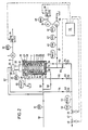
Die in der Zeichnung dargestellte Rührwerksmühle weist in üblicher Weise einen Ständer 1 auf, an dessen Oberseite ein vorkragender Tragarm 2 angebracht ist, an dem wiederum ein zylindrischer Mahlbehälter 3 befestigt ist. In dem Ständer 1 ist ein elektrischer Rührwerks-Motor 4 untergebracht, der mit einer Keilriemenscheibe 5 versehen ist, von der über Keilriemen 6 eine mit einem Rührwerk 7 drehfest verbundene Keilriemenscheibe 8 drehend antreibbar ist.The agitator mill shown in the drawing has in the usual way a
Der vertikal angeordnete Mahlbehälter 3 besteht aus einem zylindrischen, einen Mahlraum 9 umgebenden, gleichzeitig die Mahlbehälterwand bildenden Innenzylinder 10, der von einem ebenfalls im wesentlichen zylindrischen Kühlmantel 11 umgeben ist. Der untere Abschluß des Mahlraumes 9 und des Kühlmantels 11 ist durch eine Bodenplatte 12 gegeben, die am Innenzylinder 10 und am Kühlmantel 11 beispielsweise durch Anschrauben befestigt ist. An der Bodenplatte 12 ist ein Mahlgutzuführstutzen 13 angebracht, durch den Mahlgut von unten in den Mahlraum 9 hineingepumpt werden kann. Am Kühlmantel 11 sind ein oberer Kühlwassereinlaßstutzen 14 und ein unterer Kühlwasseraustrittsstutzen 15 vorgesehen. In der Bodenplatte 12 ist weiterhin ein Ablaßstutzen 16 für Mahlhilfskörper vorgesehen.The vertically arranged
Der Mahlbehälter 3 weist einen oberen Ringflansch 17 auf, mittels dessen er an einem den Mahlraum 9 verschließenden Deckel 18 befestigt ist Dieser Deckel 18 ist an der Unterseite eines Traggehäuses 19 angebracht, das mit seinem oberen Ende am Tragarm 2 der Rührwerksmühle befestigt ist. In diesem Traggehäuse 19 ist eine einen wesentlichen Teil des Rührwerks 7 ausmachende Rührwerkswelle 20 in üblicher Weise fliegend in Lagern 21 gelagert, wie es beispielsweise aus der DE-A-26 29 251 (entsprechend US-A-4 129 261) bekannt ist. Die Rührwerkswelle 20 ist in ebenfalls aus der erwähnten Druckschrift bekannter Weise abgedichtet durch den Deckel 18 hindurchgeführt. Das Rührwerk 7 weist in aus der erwähnten Druckschrift bekannter Weise auf der Rührwerkswelle 20 angebrachte Scheiben 23 auf, von denen als Rührwerkzeuge Rührstäbe 24 radial vorragen. Am Innenzylinder 10 sind jeweils axial gegen die Rührstäbe 24 versetzt Gegenstäbe 25 angebracht.The
Am oberen Ende des Mahlraums 9, also an dem dem Mahlgutzuführstutzen 13 entgegengesetzten Ende des Mahlraums 9 ist ein Mahlgutauslaßstutzen 26 vorgesehen, dem eine sogenannte Ringspalttrenneinrichtung 27 vorgeordnet ist, mittels der die Mahlhilfskörper 28 im Mahlraum 9 zurückgehalten werden.At the upper end of the
Eine derartige Trenneinrichtung 27 ist ebenfalls aus der erwähnten Druckschrift bekannt. Wie ebenfalls aus der erwähnten Druckschrift bekannt ist, ist das Rührwerk 7 kühlbar. Hierzu ist in bekannter Weise an dem der Keilriemenscheibe 8 zugeordneten Ende der Rührwerkswelle 20 ein Kühlwasseranschluß 29 und ein Kühlwasserabfluß 30 vorgesehen. Wie aus Fig. 2 hervorgeht, kann auch die Bodenplatte 12 kühlbar, also hohl, ausgebildet sein und mit einem Kühlwasserzufluß 31 und einem Kühlwasserabfluß 32 versehen sein.Such a
Der Detailaufbau der Rührwerksmühle ist für die Erfindung ohne Bedeutung ; es können also jede Art von Rührwerkzeugen eingesetzt werden. Auch der Deckel 18 kann kühlbar ausgebildet sein. Gleichermaßen kommt es auf die konkrete Ausbildung der Trenneinrichtung in diesem Zusammenhang nicht an.The detailed structure of the agitator mill is of no importance for the invention; So any kind of stirring tools can be used. The
Der Mahlraum 9 ist 50 bis 90 % mit Mahlhilfskörpern 28 gefüllt, die einen Durchmesser im Bereich von 0,3 bis 10 mm haben.The grinding
Ein erstes Schaltungsschema wird nachfolgend anhand der Fig. 2 erläutert.A first circuit diagram is explained below with reference to FIG. 2.
Mit ausgezogenen Linien sind in der Regel Flüssigkeitsleitungen gezeichnet, während gestrichelt Steuerleitungen dargestellt sind, die von einem zentralen Rechner 33 zu verschiedenen Stellen führen, wo ein vom Rechner gesteuerter Vorgang ausgelöst werden soll.Solid lines are generally drawn with solid lines, while dashed lines show control lines which lead from a
Die Stromversorgung des Rührwerks-Motors 4 erfolgt über einen vom Rechner 33 angesteuerten Frequenzumformer 34, so daß eine feinfühlige Drehzahlsteuerung des Motors 4 und damit des Rührwerks 7 möglich ist. Die Leistungsaufnahme des Rührwerks-Motors 4 wird an einer Meßstelle 35 erfaßt. In den Darstellungen der Meßstellen sind Kennbuchstaben angebracht, die bei allen noch zu erwähnenden Meßstellen folgende Bedeutung haben :

Im konkreten Fall der Meßstelle 35 bedeuten die dort angegeben Buchstaben, daß die erfaßte elektrische Leistung angezeigt, registriert und zum Rechner gegeben wird.In the specific case of the
Die Mahlgutzufuhr erfolgt mittels einer Mahlgut-Pumpe 36 über eine Mahlgut-Zulaufleitung 37 zum Mahlgutzuführstutzen 13 des Mahlbehälters 3. Die Pumpe 36 wird mittels eines elektrischen Pumpenmotors 38 angetrieben, dessen Stromversorgung über einen Frequenzumformer 39 erfolgt, so daß die Drehzahl des Pumpenmotors 38 und damit die Förderleistung der Pumpe 36 sehr genau steuerbar ist Auch dieser Frequenzumformer wird vom Rechner 33 angesteuert. Dem Pumpenmotor 38 ist eine Meßstelle 40 zur Erfassung der aufgenommenen elektrischen Leistung zugeordnet. Weiterhin ist eine Meßstelle 41 zur Erfassung der Pumpenmotor- bzw. Pumpendrehzahl zugeordnetThe millbase is fed in by means of a
In der Mahlgut-Zulaufleitung 37 sind weiterhin eine Meßstelle 42 zur Erfassung der Temperatur des zuzuführenden Materials, eine Meßstelle 43 zur Erfassung des von der Mahlgut-Pumpe geförderten Mahlgut-Massenstroms und eine Meßstelle 44 zur Erfassung des Mahlgut-Drucks vor dem bzw. am Eingang des Mahlraums 9.In the
Dem Mahlgutauslaßstutzen 26 ist eine Meßstelle 45 zur Erfassung der Temperatur des austretenden gemahlenen Mahlguts zugeordnet. Der Rührwerkswelle 20 ist eine Meßstelle 46 zum Erfassen der Drehzahl der Rührwerkswelle 20 zugeordnet.A measuring
Die Kühlwasserzufuhr erfolgt über eine zentrale Kühlwasser-Leitung 47, in der ein vom Rechner 33 ansteuerbares Absperr-Ventil 48 angeordnet ist dem ein ebenfalls vom Rechner 33 angesteuertes Proportional-Ventil 49 nachgeordnet ist, dessen Absperrverhalten also proportional dem Öffnungs- oder Schließgrad ist. Solche handelsüblichen Ventile eignen sich also besonders gut zur Volumenstrom-Steuerung, im vorliegenden Fall also zur Kühlwasserstrom-Steuerung.The cooling water supply takes place via a central
Hinter dem Ventil 49 sind in der Leitung 47 eine Meßstelle 52 zur Erfassung der Kühlwasser-Vorlauf-Temperatur und eine Meßstelle 53 zur Erfassung des Volumenstroms des Kühlwasser-Vorlaufs angeordnet. Das durch das Ventil 49 und die Meßstellen 52, 53 fließende Kühlwasser wird in mehrere Kühlwasser-Vorlauf-Zweigleitungen 54, 55, 56 aufgeteilt. Die Zweigleitung 54 führt zum Kühlwasseranschluß 29 der Rührwerkswelle 20, die Zweigleitung 55 führt zum Kühlwassereinlaßstutzen 14 des Kühlmantels 11 und die Zweigleitung 56 führt zum Kühlwasserzufluß 31 des Bodens 12 des Mahlbehälters 3. Das aus der Rührwerkswelle kommende Rücklauf-Kühlwasser fließt über eine Kühlwasser-Rücklauf-Teilleitung 57 zu einem Kühlwasser-Rücklauf-Sammelleitung 58. Vom Kühlwasserauslaßstutzen 15 des Kühlmantels 11 führt eine Kühlwasser-Rücklauf-Teilleitung 59 und vom Kühlwasserabfluß 32 des Bodens 12 eine Kühlwasser-Rücklauf-Teilleitung 60 zu der Sammelleitung 58, in der sich eine Meßstelle 61 zur Erfassung der Kühlwasser-Rücklauf-Temperatur befindet. Die Aufteilung des Kühlwasser-Vorlaufs auf die drei Zweigleitungen 54, 55, 56 erfolgt mittels handverstellbarer Ventile 62, 63, 64 in diesen Zweigleitungen 54, 55, 56. Anstelle dieser handverstellbaren Ventile können selbstverständlich auch vom Rechner angesteuerte Proportional-Ventile vorgesehen sein, so daß eine Einzel-Steuerung der Kühlwasser-Teil-Volumenströme möglich ist.Behind the
Es ist weiterhin eine Einrichtung 66 zur Zuführung von Mahlhilfskörpern 28 vorgesehen, die ebenfalls vom Rechner 33 ansteuerbar ist Solche Einrichtungen sind beispielsweise aus der DE-C-20 51 003 bekannt. Die Zuführung von Mahlhilfskörpern 28 mittels dieser Einrichtung 66 erfolgt in die Mahlgut-Zulaufleitung 37 unmittelbar vor dem Mahlgutzuführstutzen 13.A
Während bei dem Ausführungsbeispiel nach Fig. 2 vom Innenzylinder 10 und dem Kühlmantel 11 ein sich im wesentlichen über die volle axiale Länge des Mahlraums 9 erstreckender Kühlraum 11' gebildet wird, ist bei dem Ausführungsbeispiel nach Fig. 3 dieser Kühlraum etwa in der axialen Mitte durch eine Trennwand 67 unterteilt, so daß zwei Teil-Kühlräume 11'a und 11'b gebildet werden. Der eine Teil-Kühlraum 11'a ist dem Teil-Mahlraum 9a zugeordnet, der sich an den Mahlgutzuführstutzen 13 anschließt. Der andere Teil-Kühlraum 11'b ist dem Teil-Mahlraum 9b zugeordnet, der sich vor der Trenneinrichtung 27, also vor dem Mahlgutauslaßstutzen 26 befindet. Soweit gleiche Teile bei diesem Ausführungsbeispiel vorhanden sind, werden die gleichen Bezugsziffern wie in Fig. 2 verwendet, wobei von einer erneuten Beschreibung Abstand genommen wird.While in the embodiment according to FIG. 2 the
Zur Versorgung der beiden Teil-Kühlräume 11'a und 11'b sind entsprechende Kühlwasser-Vortauf-Zweigleitungen 54a und 54b vorgesehen, die von der Kühlwasser-Vorlauf-Leitung 47 abzweigen. In beiden Zweigleitungen 54a und 54b sind ebenfalls handverstellbare Ventile 63a und 63b vorgesehen. Auch hier können anstelle der handverstellbaren Ventile 63a und 63b vom Rechner angesteuerte Proportional-Ventile vorgesehen sein.Corresponding cooling
Von den Teil-Kühlräumen 11'a und 11'b führen Kühlwasser-Rücklauf-Teilleitungen 59a und 59b zur Kühlwasser-Rücklauf-Sammelleitung 58.Cooling water return
In den beiden Zweigleitungen 54a und 54b befinden sich Meßstellen 68a bzw. 68b zur Messung des Kühlwasser-Volumenstroms, also zur Messung der Kühlwassermenge pro Zeiteinheit in der jeweiligen Zweigleitung 54a bzw. 54b.In the two
In den beiden Kühlwasser-Rücklauf-Teilleitungen 59a und 59b sind Meßstellen 69a und 69b zur Messung der Temperatur des entsprechend Rücklauf-Kühlwassers angeordnet.Measuring
Mit den zusätzlich vorgesehenen Meßstellen lassen sich also Volumenstrom und Austrittstemperatur des Kühlwassers in den beiden Teil-Kühlräumen 11'a und 11'b erfassen, die der unteren Mahlraumhälfte 9a bzw. der oberen Mahlraumhälfte 9b zugeordnet sind. Der unteren Mahlraumhälfte 9a kann als Teil-Kühlraum auch die kühlbare Bodenplatte 12 mit entsprechender in der geschilderten Weise mit Meßstellen versehener Kühlwasserversorgung zugeordnet werden. Entsprechendes gilt für die obere Mahlraumhälfte 9b, wenn der Deckel 18 in der bereits angesprochenen Weise kühlbar ausgebildet ist.With the additionally provided measuring points, volume flow and outlet temperature of the cooling water in the two partial cooling rooms 11'a and 11'b can be determined, which are assigned to the lower
Die Betriebsweise ist wie folgt :The mode of operation is as follows:
Grundvoraussetzung ist, daß für einen bestimmten Bearbeitungsfall der spezifische Energieeintrag in das Mahlgut, d.h. der Quotient aus dem durch das Rührwerk 7 in das Mahlgut eingebrachter Leistung und aus dem Mahlgut-Massenstrom, d.h. dem pro Zeiteinheit dem Mahlraum 9 zugeführter Mahlgut-Masse unter Berücksichtigung einer zulässigen Abweichung, konstant gehalten werden soll. Der Wert des spezifischen Energieeintrags für den konkreten Mahlfall wird empirisch im Labor oder Technikum unter ähnlichen Bedingungen in verkleinertem Maßstab ermittelt. Eine solche Rührwerksmühle zur Ermittlung eines solchen Wertes sollte also einen ähnlich gestalteten Mahlbehälter und ein ähnlich gestattetes Rührwerk einschließlich ähnlicher Rührwerkzeuge aufweisen.The basic requirement is that the specific energy input into the regrind, i.e. the quotient of the power introduced into the millbase by the
Regelgrößen für den spezifischen Energieeintrag sind der Leistungseintrag in das im Mahlraum 9 befindliche Mahlgut einerseits und der Mahlgut-Massenstrom. Stellgrößen hierfür sind wiederum die Leistungsaufnahme des Rührwerks-Motors 4, und zwar die Wirkleistungsaufnahme abzüglich einer empirisch zu erfassenden und im Rechner 32 abzuspeichernden Leerlaufleistung von Motor 4 und Rührwerksmühle (ohne Mahlhilfskörper-Füllung).Control variables for the specific energy input are, on the one hand, the power input into the ground material in the grinding
Als Stellgröße für den Leistungseintrag in den Prozeßraum dient die Drehzahl des Rührwerks 7 und/oder der Füllgrad, mit dem der Mahlraum 9 mit Mahlhilfskörpern 28 gefüllt ist. Die Drehzahl des Rührwerks 7 wird über den Frequenzumformer 34 eingestellt. Der Mahlkörperfüllgrad wird über die Einrichtung 66 zur Zuführung von Mahlhilfskörpern 28, die beide vom Rechner 33 ansteuerbar sind, verändert.The speed of the
Eine wesentliche übergeordnete Größe ist die Soll-Temperatur des Mahlgutes am Austritt 26. Bei Überschreiten einer maximal zulässigen Mahlguttemperatur kann eine Schädigung des Mahlgutes eintreten. Beispielsweise kann eine Beeinträchtigung von gewünschten coloristischen Eigenschaften auftreten, es können gefährliche Lösungsmittelverdampfungen auftreten, chemische Additive wie Dispergatoren und Stabilisatoren können thermisch abgebaut werden. Aus diesem Grunde können die Regelung der Leistungsaufnahme und/oder des Mahlgut-Massenstroms zur Konstanthaltung der massespezifischen Energiezufuhr nur jeweils unter Berücksichtigung einer maximal zulässigen Temperatur des Mahlgutes, die an der Meßstelle 45 erfaßt wird, verändert werden. Diese maximal zulässige Temperatur liegt um eine zulässige Temperaturabweichung oberhalb der Solltemperatur.An essential overriding variable is the target temperature of the millbase at the
Stellgröße zur Regelung einer konstanten Mahlgut-Austrittstemperatur ist der Volumenstrom des Kühlwassers. Dieser wird entsprechend der an der Meßstelle 45 gemessenen Mahlgut-Austrittstemperatur - angesteuert vom Rechner 33 - durch eine Stellung des Proportional-Ventils 49 eingestellt. Die Aufteilung auf die einzelnen Zweigleitungen 54, 55, 56 erfolgt über eine manuelle Grundeinstellung der Ventile 62, 63, 64. Wenn das Ventil 49 bereits vollständig geöffnet ist, dann kann eine Reduktion der Mahlgut-Austrittstemperatur nur noch durch eine Reduktion des Leistungseintrags über das Rührwerk 7 unter entsprechender Verringerung des Mahlgut-Massenstroms erreicht werden.The manipulated variable for controlling a constant regrind outlet temperature is the volume flow of the cooling water. This is set in accordance with the ground material outlet temperature measured at the measuring point 45 - controlled by the computer 33 - by means of a position of the
Die Drehzahl des Rührwerks 7 kann - zur Veränderung des Leistungseintrags in das Mahlgut innerhalb eines Drehzahlregelbereiches um die Soll-Drehzahl geregelt werden. Dieser Drehzahlregelbereich liegt beispielsweise in einem Bereich von 10 % um die Solldrehzahl.The speed of the
Die Ist-Drehzahl des Rührwerks 7 wird von der Meßstelle 46 auf den Rechner 33 gegeben.The actual speed of the
Der Mahlgut-Massenstrom wird nach oben durch eine maximale Leistungsaufnahme und eine maximale Drehzahl des Pumpen-Motors 38 und durch einen maximal zulässigen Druck begrenzt. Die Leistungsaufnahme wird von der Meßstelle 40 erfaßt und zum Rechner gegeben. Da die an der Meßstelle 41 erfaßte Drehzahl des Pumpen-Motors 38 bzw. der Mahlgutpumpe 36 nur einen indirekten Hinweis auf den Mahlgut-Massenstrom gibt und da zu hoher Gegendruck, Lufteinschlüsse und weitere Störeinflüsse die Förderung der Mahlgut-Pumpe 36 beeinträchtigen können, wird der tatsächliche Massenstrom an der Meßstelle 43 erfaßt und auf den Rechner gegeben.The ground material mass flow is limited by a maximum power consumption and a maximum speed of the
Bei dem Ausführungsbeispiel nach Fig. 2 wird eine gleichmäßige Mahlkörperverteilung im Mahlraum 9 durch eine Erfassung des Mahlgut-Druckes an der Meßstelle 44 unmittelbar vor dem Mahlraum erfaßt. Da das Mahlgut hinter der Trenneinrichtung 27 Atmosphärendruck unterliegt, gibt der an der Meßstelle 44 erfaßte Mahlgut-Druck den Druckverlust im Mahlraum 9 wieder. Bei einer gleichmäßigen Verteillung der Mahlhilfskörper 28 im Mahlraum ist ein Mahlgut-Solldruck gegeben. Ein Überschreiten dieses Soll-Druckes über eine zulässige Abweichung hinaus zeigt an, daß eine übermäßige Mahlkörperkonzentration entweder am Mahlguteinlaß, also am Boden des Mahlraums 9 oder im Bereich des Mahlgutauslasses vor der Trenneinrichtung 27 erfolgt ist.In the exemplary embodiment according to FIG. 2, a uniform distribution of the grinding media in the grinding
Eine gleichmäßige Mahlkörperverteilung im Mahlraum 9 liegt dann vor, wenn die an den Mahlhilfskörpern 28 angreifenden Kräfte, nämlich die Schwerkraft, die Auftriebs- und Strömungskräfte, sich im Gleichgewicht befinden. Wenn die Schwerkraft überwiegt, tritt eine übermäßige Konzentration von Mahlkörpern am Boden des Mahlraums ein. Wenn die Auftriebs- und Strömungskräfte überwiegen, tritt eine übermäßige Konzentration vor der Trenneinrichtung ein. In beiden Fällen tritt ein erhöhter Druckabfall im Mahlraum ein, d.h. der an der Meßstelle 44 erfaßte Mahlgut-Druck steigt an. Des weiteren nimmt die lediglich zum Rühren der aufkonzentrierten Mahlhilfskörper 28, nicht in Mahlleistung umgesetzte Verlustleistung zu, d.h. eine übermäßige Konzentration der Mahlhilfskörper 28 im Bereich des Mahlguteinlasses oder vor der Trenneinrichtung 27 führt zu einer verstärkten Erwärmung des Mahlgutes und zu stark erhöhtem Verschleiß der Mahlhilfskörper 28, der Rührwerkzeuge und der Mahlraumbegrenzungswände.A uniform grinding media distribution in the grinding
Eine Aussage über die Frage, ob die Ursache einer Druckerhöhung in einer Konzentration von Mahlhilfskörpern 28 am Boden des Mahlraums 9 oder vor der Trenneinrichtung 27 ist, läßt sich im wesentlichen aus der « Geschichte )) der Druckerhöhung herleiten. Wenn bei einer Erhöhung des Mahlgut-Massenstroms durch entsprechende Erhöhung der Drehzahl der Mahlgut-Pumpe 36 der Mahlgut-Druck an der Meßstelle 44 ansteigt, dann ist dies ein Indiz dafür, daß eine übermäßige Konzentration an Mahlhilfskörpern 28 vor der Trenneinrichtung 27 erfolgt ist, während eine Abnahme des Druckes anzeigt, daß die Mahlhilfskörper 28 im Bereich des Mahlguteinlasses übermäßig konzentriert sind, wobei durch Erhöhung des Volumenstroms die auf die Mahlhilfskörper 28 wirkenden Strömungskräfte erhöht werden mit der Konsequenz, daß die Verteilung vergleichmäßigt wird. Ist dagegen - wie erläutert - eine übermäßige Konzentration vor der Trenneinrichtung 27 erfolgt, so muß der Mahlgut-Massenstrom zurückgenommen werden.A statement on the question of whether the cause of a pressure increase is a concentration of auxiliary grinding
Der spezifische Energieeintrag durch das Rührwerk 7 in das im Mahlraum 9 befindliche Mahlgut läßt sich nicht mehr konstant halten, wenn beide bestimmenden Größen ihren entsprechenden Extremwert erreicht haben. Wenn also der Mahlgut-Massenstrom bereits auf ein Minimum heruntergeregelt ist und die Drehzahl des Rührwerks 7 auf den maximal zulässigen Wert hochgeregelt worden ist, dann wird vom Rechner 33 her über die Einrichtung 66 die Nachfüllung des Mahlraums 9 mit Mahlhilfskörpern 28 in die Wege geleitet. Gleichzeitig wird die Drehzahl zurückgeregelt.The specific energy input by the
Bei dem in Fig. 3 dargestellten Ausführungsbeispiel wird die bereits erwähnte durch zusätzliche Verlustleistungen bedingte Erwärmung des Mahlgutes im Bereich einer übermäßigen Konzentration von Mahlhilfskörpern 28 erfaßt. Hierzu wird die Erwärmung des Kühlwassers im Teil-Kühlraum 11'a und andererseits im Teil-Kühlraum 11'b erfaßt, und zwar durch Erfassen der Kühlwasser-Vorlauf-Temperatur an der Meßstelle 52 und durch Erfassen der Kühlwasser-Rücklauf-Temperaturen an den Meßstellen 69a und 69b. Durch gleichzeitiges Erfassen der Kühlwasser-Volumenströme an den Meßstellen 68a und 68b ist im Rechner 33 in einfacher Weise die einerseits im Teil-Kühlraum 11a aufgenommene Wärme und die andererseits im Teil-Kühlraum 11 aufgenommene Wärme ermittelt werden. Deren Verhältnis zueinander sind unmittelbar ein Maß dafür, ob entweder am Mahlguteinlaß oder vor der Trenneinrichtung 27 eine übermäßige Konzentration von Mahlhilfskörpern 28 erfolgt ist. Wenn mehr Wärme im Bereich des Teil-Kühlraums 11'a übertragen wird, ist ersteres der Fall, während bei einer größeren Wärmeübertragung im Bereich des Teil-Kühlraums 11'b letzteres der Fall ist. Abhilfe wird auch hier in der gleichen Weise geschaffen, wie bei dem Ausführungsbeispiel nach Fig. 2.In the exemplary embodiment shown in FIG. 3, the heating of the material to be ground, which has already been caused by additional power losses, is detected in the region of an excessive concentration of auxiliary grinding
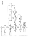
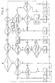
Auf der Basis der vorstehenden allgemeinen Erläuterungen sind die Flußdiagramme nach den Fig. 4, 5 und 6, 7 aus sich heraus verständlich, wobei das Flußdiagramm nach den Fig. 4, 5 die Regelung der Mahlkörperverteilung über die Erfassung des Mahlgut-Druckes vor dem Mahlraum wiedergibt, während das Flußdiagramm nach den Fig. 6 und 7 die Regelung der Mahlkörperverteilung über die Erfassung der Wärmeströme Qu bzw. Qo im unteren und oberen Teil 9a bzw. 9b des Mahlraums 9 wiedergibt. Ansonsten sind die Regelungsschemen gleich. Sie beschreiben entsprechend der Erfindung vollautomatische Regelungen.Based on the above general explanations, the flow diagrams according to FIGS. 4, 5 and 6, 7 are understandable in themselves, the flow diagram according to FIGS. 4, 5 regulating the grinding media distribution via the detection of the grinding stock pressure in front of the grinding
In den Flußdiagrammen haben die nachfolgend aufgelisteten Zeichen die jeweils angegebene Bedeutung :

Es werden folgende Indizes verwendet :
In den Rhomben in den Fig. 4 bis 6 sind die jeweils vom Rechner durchzuführenden Vergleichsoperationen angegeben, die mit den Meßdaten durchgeführt werden, die von den einzelnen Meßstellen zum Rechner 33 gegeben werden. Die aus den einzelnen Rhomben herausführenden Pfeile mit dem Zusatz « nein )) oder « ja » geben an, welche Operation als nächstes durchgeführt wird, wenn die in einem Rhombus angegebene Bedingung erfüllt (ja) oder nicht erfüllt (nein) ist. Die in Rechtecken angegebenen Maßnahmen geben an, welche Stellgroße unter entsprechender Ansteuerung des zugeordneten Stellgliedes vom Rechner her verändert wird, wenn ein oder mehrere (in Rhomben angegebene) Bedingungen erfüllt sind.The rhombuses in FIGS. 4 to 6 indicate the comparison operations to be carried out by the computer, which are carried out with the measurement data which are passed from the individual measurement points to the
In Einzelfällen sind in den Rechtecken Ziffern angegeben. Es handelt sich hierbei um die Bezugsziffern des entsprechenden Stellgliedes aus Fig. 2 oder 3.In individual cases, numbers are given in the rectangles. These are the reference numbers of the corresponding actuator from FIG. 2 or 3.
Vor Beginn des Mahlens werden die nachfolgend aufgelisteten Parameter in den Rechner 33 eingegeben, die sich auf einen speziellen Mahlvorgang mit den entsprechenden Bedingungen beziehen :

Bei der Ausführung nach Fig. 3 entsprechend dem Flußdiagramm nach Fig. 4 und 6 wird zusätzlich noch zur Erfassung der in den Teil-Kühlräumen abgeführten Wärmeströme eingegeben die zulässige Differenz der abgeführten Wärmeströme:
![]()
![]()
Wie sich aus Fig. 4 ergibt, werden nach dem Start der Druck und die Temperatur im Hinblick auf die maximal zulässigen Werte überprüft und bei Erreichen des maximal zulässigen Wertes eine Notabschaltung (NOTAUS) durchgeführt. Anschließend werden weitere Temperatur- und Druckbedingungen abgefragt und jeweils bei Nichtvorhandensein die entsprechenden oben geschilderten Maßnahmen ergriffen. Wenn Druck und Temperatur des Mahlgutes im Bereich der zulässigen Abweichung sind, wird der tatsächliche spezifische Energieeintrag überprüft, und zwar im Hinblick auf die zulässige Abweichung. Je nachdem ob eine Abweichung vorliegt oder nicht, erfolgen dann die im einzelnen in den Fig. 5 bzw. 6 angegebenen weiteren Abfragen bzw. Maßnahmen.As can be seen from FIG. 4, the pressure and the temperature are checked with regard to the maximum permissible values after the start and an emergency shutdown (EMERGENCY STOP) is carried out when the maximum permissible value is reached. Subsequently, further temperature and pressure conditions are queried and the corresponding measures described above are taken in the absence of any. If the pressure and temperature of the material to be ground are in the range of the permissible deviation, the actual specific energy input is checked, with regard to the permissible deviation. Depending on whether there is a deviation or not, the further queries or measures specified in FIGS. 5 and 6 then take place.
Wenn das Programm des Rechners jeweils durchgefahren ist, springt er zurück zum Anfang A und fährt erneut eine Schleife durch.When the program of the computer has run through, it jumps back to start A and loops again.
Claims (11)
Applications Claiming Priority (2)
| Application Number | Priority Date | Filing Date | Title |
|---|---|---|---|
| DE3614980A DE3614980C1 (en) | 1986-05-02 | 1986-05-02 | Control device for a agitator mill |
| DE3614980 | 1986-05-02 |
Publications (4)
| Publication Number | Publication Date |
|---|---|
| EP0243682A2 EP0243682A2 (en) | 1987-11-04 |
| EP0243682A3 EP0243682A3 (en) | 1988-08-17 |
| EP0243682B1 EP0243682B1 (en) | 1990-01-03 |
| EP0243682B2 true EP0243682B2 (en) | 1994-11-02 |
Family
ID=6300080
Family Applications (1)
| Application Number | Title | Priority Date | Filing Date |
|---|---|---|---|
| EP87104450A Expired - Lifetime EP0243682B2 (en) | 1986-05-02 | 1987-03-25 | Control of an agitator mill |
Country Status (4)
| Country | Link |
|---|---|
| US (1) | US4848676A (en) |
| EP (1) | EP0243682B2 (en) |
| JP (1) | JPS6323753A (en) |
| DE (2) | DE3614980C1 (en) |
Families Citing this family (18)
| Publication number | Priority date | Publication date | Assignee | Title |
|---|---|---|---|---|
| DE3730426A1 (en) * | 1987-09-10 | 1989-03-23 | Netzsch Erich Holding | METHOD FOR REGULATING A AGITATOR MILL |
| US5114083A (en) * | 1988-06-10 | 1992-05-19 | Kubota, Ltd. | Method and appatatus for pulverizing material |
| DE3920273A1 (en) * | 1989-06-21 | 1991-01-03 | Hermann Getzmann | METHOD AND DEVICE FOR REGULATING THE SPEED OF AGITOR BALL MILLS |
| US5024387A (en) * | 1989-07-25 | 1991-06-18 | E. I. Du Pont De Nemours And Company | On line control method to determine media fluidization in a media mill |
| ES2030618A6 (en) * | 1990-10-31 | 1992-11-01 | Oliver & Battle Sa | Mill for triturating and breaking up solids predispersed in liquids. |
| DE4432153A1 (en) * | 1994-09-09 | 1996-03-14 | Evv Vermoegensverwaltungs Gmbh | Method and device for the continuous autogenous grinding of a flowable material to be treated |
| US6431478B1 (en) * | 1999-06-01 | 2002-08-13 | Elan Pharma International Limited | Small-scale mill and method thereof |
| DE10011579B4 (en) | 2000-03-09 | 2007-06-06 | BüHLER GMBH | agitating mill |
| ATE453454T1 (en) | 2000-04-26 | 2010-01-15 | Elan Pharma Int Ltd | DEVICE FOR SANITARY WET GRINDING |
| US20030087308A1 (en) * | 2001-06-22 | 2003-05-08 | Elan Pharma International Limited | Method for high through put screening using a small scale mill or microfluidics |
| WO2004058216A2 (en) * | 2002-12-17 | 2004-07-15 | Elan Pharma International Ltd. | Milling microgram quantities of nanoparticulate candidate compounds |
| JP2006255563A (en) * | 2005-03-16 | 2006-09-28 | Toho Gas Co Ltd | Crusher |
| US7571871B2 (en) * | 2005-11-04 | 2009-08-11 | Rutgers, The State University Of New Jersey | Uniform shear application system and methods relating thereto |
| EP2377405B1 (en) | 2010-04-13 | 2013-06-05 | Albert Handtmann Maschinenfabrik GmbH & Co. KG | Device and method for producing and filling fine sausage meat, in particular an emulsion |
| JP5931714B2 (en) * | 2012-12-27 | 2016-06-08 | 株式会社アーステクニカ | Crusher |
| EP3799960B1 (en) * | 2019-10-01 | 2025-04-02 | Bühler AG | Agitator mill |
| CN115518764A (en) * | 2022-10-12 | 2022-12-27 | 深圳市尚水智能设备有限公司 | Feeding control method of vertical grinding machine and vertical grinding machine |
| CN115591634B (en) * | 2022-10-12 | 2023-11-03 | 深圳市尚水智能股份有限公司 | Vertical medium grinds machine |
Family Cites Families (5)
| Publication number | Priority date | Publication date | Assignee | Title |
|---|---|---|---|---|
| DE2629251C2 (en) * | 1976-06-30 | 1987-03-19 | Draiswerke Gmbh, 6800 Mannheim | Agitator mill |
| AT367657B (en) * | 1978-08-24 | 1982-07-26 | Buehler Ag Geb | AGITATOR BALL MILL CONTROL |
| DE3136323A1 (en) * | 1981-09-12 | 1983-03-31 | Boehringer Mannheim Gmbh, 6800 Mannheim | METHOD FOR OPERATING A BALL MILL AND CORRESPONDING BALL MILL |
| EP0109157A3 (en) * | 1982-10-15 | 1986-03-05 | Morehouse Industries, Inc. | Automated sandmill control system |
| DE3249928C3 (en) * | 1982-12-10 | 1995-06-29 | Buehler Ag Geb | Agitator mill |
-
1986
- 1986-05-02 DE DE3614980A patent/DE3614980C1/en not_active Expired - Fee Related
-
1987
- 1987-03-25 DE DE8787104450T patent/DE3761288D1/en not_active Expired - Lifetime
- 1987-03-25 EP EP87104450A patent/EP0243682B2/en not_active Expired - Lifetime
- 1987-05-01 JP JP62106488A patent/JPS6323753A/en active Granted
-
1988
- 1988-09-15 US US07/244,809 patent/US4848676A/en not_active Expired - Lifetime
Also Published As
| Publication number | Publication date |
|---|---|
| JPS6323753A (en) | 1988-02-01 |
| US4848676A (en) | 1989-07-18 |
| JPH0418900B2 (en) | 1992-03-30 |
| EP0243682A3 (en) | 1988-08-17 |
| DE3614980C1 (en) | 1993-05-27 |
| EP0243682B1 (en) | 1990-01-03 |
| DE3761288D1 (en) | 1990-02-08 |
| EP0243682A2 (en) | 1987-11-04 |
Similar Documents
| Publication | Publication Date | Title |
|---|---|---|
| EP0243682B2 (en) | Control of an agitator mill | |
| DE2932783C3 (en) | Agitator ball mill regulation | |
| EP2178643B1 (en) | Stirrer mill | |
| DE69014227T2 (en) | Mixer and method for controlling this mixer. | |
| DE3139760A1 (en) | ROLLING MILL WITH ADJUSTABLE SPEED IN A FIXED SPEED RATIO, THE INLET GAP FOR THE WELL-MAKING ROLLS AND METHOD FOR USE THEREOF | |
| CH695208A5 (en) | Agitator mill. | |
| DE2839264A1 (en) | METHOD FOR GRINDING AND CRUSHING AND MACHINE FOR CARRYING OUT THIS METHOD | |
| EP0700721A1 (en) | Agitator mill | |
| EP0042927B1 (en) | Method for the regulation of a crushing plant | |
| CH692274A5 (en) | Continuous mixers, mixing plant with a continuous mixer and method of operation of such a plant. | |
| DE9017817U1 (en) | Grist mill, especially wet grist mill for mash production in beer production | |
| EP0165429B1 (en) | Process for operating a crushing mill, and crushing mill working by this process | |
| DE2807691B1 (en) | Method and device for regulating the fineness of finished goods from a grinding plant | |
| EP3954462B1 (en) | Comminuting device with cooling device and method of operating the same | |
| DE19681222B4 (en) | Mobile crusher and crusher control method | |
| DE2145096C (en) | Device for automatic grinding gap control in a mill | |
| DE2832903C2 (en) | Agitator mill - warehouse | |
| DE4311689C2 (en) | Centrifugal vibratory grinding machine with gap adjustment | |
| DE102016217295A1 (en) | Mixing device, in particular so-called internal mixer | |
| DE3338625A1 (en) | Calender | |
| DE2145096B1 (en) | DEVICE FOR AUTOMATIC GRINDING GAP CONTROL IN A MILL | |
| EP4519020A1 (en) | Autonomous mill and milling method | |
| CH640751A5 (en) | Method for operating an agitator mill and control arrangement for carrying out the method | |
| CH641059A5 (en) | Agitator mill with an electromotively driven agitator mechanism | |
| DE2449344A1 (en) | Milling apparatus control for oil extraction - with temperature sensor alongside the rolls to actuate a control device to keep the gap constant |
Legal Events
| Date | Code | Title | Description |
|---|---|---|---|
| PUAI | Public reference made under article 153(3) epc to a published international application that has entered the european phase |
Free format text: ORIGINAL CODE: 0009012 |
|
| AK | Designated contracting states |
Kind code of ref document: A2 Designated state(s): BE CH DE FR GB IT LI NL |
|
| XX | Miscellaneous (additional remarks) |
Free format text: EIN ANTRAG GEMAESS REGEL 88 EPUE AUF BERICHTIGUNG DER FIGUREN 4. SUND 6, LIEGT VOR. UEBER DIESEN ANTRAG WIRD IM LAUFE DES VERFAHRENS VON DER PRUEFUNGSABTEILUNG EINE ENTSCHEIDUNG GETROFFEN WERDEN. |
|
| PUAL | Search report despatched |
Free format text: ORIGINAL CODE: 0009013 |
|
| AK | Designated contracting states |
Kind code of ref document: A3 Designated state(s): BE CH DE FR GB IT LI NL |
|
| 17P | Request for examination filed |
Effective date: 19880921 |
|
| 17Q | First examination report despatched |
Effective date: 19881219 |
|
| GRAA | (expected) grant |
Free format text: ORIGINAL CODE: 0009210 |
|
| AK | Designated contracting states |
Kind code of ref document: B1 Designated state(s): BE CH DE FR GB IT LI NL |
|
| DX | Miscellaneous (deleted) | ||
| ET | Fr: translation filed | ||
| ITF | It: translation for a ep patent filed | ||
| REF | Corresponds to: |
Ref document number: 3761288 Country of ref document: DE Date of ref document: 19900208 |
|
| PLBI | Opposition filed |
Free format text: ORIGINAL CODE: 0009260 |
|
| 26 | Opposition filed |
Opponent name: GEBRUEDER BUEHLER AG Effective date: 19900208 |
|
| NLR1 | Nl: opposition has been filed with the epo |
Opponent name: GEBRUEDER BUEHLER AG |
|
| GBT | Gb: translation of ep patent filed (gb section 77(6)(a)/1977) | ||
| ITTA | It: last paid annual fee | ||
| PUAH | Patent maintained in amended form |
Free format text: ORIGINAL CODE: 0009272 |
|
| STAA | Information on the status of an ep patent application or granted ep patent |
Free format text: STATUS: PATENT MAINTAINED AS AMENDED |
|
| 27A | Patent maintained in amended form |
Effective date: 19941102 |
|
| AK | Designated contracting states |
Kind code of ref document: B2 Designated state(s): BE CH DE FR GB IT LI NL |
|
| ET3 | Fr: translation filed ** decision concerning opposition | ||
| REG | Reference to a national code |
Ref country code: CH Ref legal event code: AEN |
|
| ITF | It: translation for a ep patent filed | ||
| NLR2 | Nl: decision of opposition | ||
| GBTA | Gb: translation of amended ep patent filed (gb section 77(6)(b)/1977) |
Effective date: 19950215 |
|
| NLR3 | Nl: receipt of modified translations in the netherlands language after an opposition procedure | ||
| PGFP | Annual fee paid to national office [announced via postgrant information from national office to epo] |
Ref country code: FR Payment date: 19960318 Year of fee payment: 10 |
|
| PGFP | Annual fee paid to national office [announced via postgrant information from national office to epo] |
Ref country code: NL Payment date: 19960328 Year of fee payment: 10 |
|
| APAC | Appeal dossier modified |
Free format text: ORIGINAL CODE: EPIDOS NOAPO |
|
| APAC | Appeal dossier modified |
Free format text: ORIGINAL CODE: EPIDOS NOAPO |
|
| PG25 | Lapsed in a contracting state [announced via postgrant information from national office to epo] |
Ref country code: NL Effective date: 19971001 |
|
| PG25 | Lapsed in a contracting state [announced via postgrant information from national office to epo] |
Ref country code: FR Free format text: LAPSE BECAUSE OF NON-PAYMENT OF DUE FEES Effective date: 19971128 |
|
| NLV4 | Nl: lapsed or anulled due to non-payment of the annual fee |
Effective date: 19971001 |
|
| REG | Reference to a national code |
Ref country code: FR Ref legal event code: ST |
|
| PGFP | Annual fee paid to national office [announced via postgrant information from national office to epo] |
Ref country code: BE Payment date: 19990407 Year of fee payment: 13 |
|
| PG25 | Lapsed in a contracting state [announced via postgrant information from national office to epo] |
Ref country code: BE Free format text: LAPSE BECAUSE OF NON-PAYMENT OF DUE FEES Effective date: 20000331 |
|
| BERE | Be: lapsed |
Owner name: DRAISWERKE G.M.B.H. Effective date: 20000331 |
|
| REG | Reference to a national code |
Ref country code: GB Ref legal event code: IF02 |
|
| PGFP | Annual fee paid to national office [announced via postgrant information from national office to epo] |
Ref country code: GB Payment date: 20020305 Year of fee payment: 16 |
|
| PGFP | Annual fee paid to national office [announced via postgrant information from national office to epo] |
Ref country code: CH Payment date: 20030219 Year of fee payment: 17 |
|
| PG25 | Lapsed in a contracting state [announced via postgrant information from national office to epo] |
Ref country code: GB Free format text: LAPSE BECAUSE OF NON-PAYMENT OF DUE FEES Effective date: 20030325 |
|
| PGFP | Annual fee paid to national office [announced via postgrant information from national office to epo] |
Ref country code: DE Payment date: 20030522 Year of fee payment: 17 |
|
| GBPC | Gb: european patent ceased through non-payment of renewal fee |
Effective date: 20030325 |
|
| PG25 | Lapsed in a contracting state [announced via postgrant information from national office to epo] |
Ref country code: LI Free format text: LAPSE BECAUSE OF NON-PAYMENT OF DUE FEES Effective date: 20040331 Ref country code: CH Free format text: LAPSE BECAUSE OF NON-PAYMENT OF DUE FEES Effective date: 20040331 |
|
| PG25 | Lapsed in a contracting state [announced via postgrant information from national office to epo] |
Ref country code: DE Free format text: LAPSE BECAUSE OF NON-PAYMENT OF DUE FEES Effective date: 20041001 |
|
| REG | Reference to a national code |
Ref country code: CH Ref legal event code: PL |
|
| PG25 | Lapsed in a contracting state [announced via postgrant information from national office to epo] |
Ref country code: IT Free format text: LAPSE BECAUSE OF NON-PAYMENT OF DUE FEES;WARNING: LAPSES OF ITALIAN PATENTS WITH EFFECTIVE DATE BEFORE 2007 MAY HAVE OCCURRED AT ANY TIME BEFORE 2007. THE CORRECT EFFECTIVE DATE MAY BE DIFFERENT FROM THE ONE RECORDED. Effective date: 20050325 |
|
| APAH | Appeal reference modified |
Free format text: ORIGINAL CODE: EPIDOSCREFNO |