EP0243596A2 - Axial drag regulator for an exhaust turbo charger for internal-combustion engines - Google Patents
Axial drag regulator for an exhaust turbo charger for internal-combustion engines Download PDFInfo
- Publication number
- EP0243596A2 EP0243596A2 EP87102412A EP87102412A EP0243596A2 EP 0243596 A2 EP0243596 A2 EP 0243596A2 EP 87102412 A EP87102412 A EP 87102412A EP 87102412 A EP87102412 A EP 87102412A EP 0243596 A2 EP0243596 A2 EP 0243596A2
- Authority
- EP
- European Patent Office
- Prior art keywords
- section
- controller according
- housing
- axial swirl
- guide vanes
- Prior art date
- Legal status (The legal status is an assumption and is not a legal conclusion. Google has not performed a legal analysis and makes no representation as to the accuracy of the status listed.)
- Granted
Links
- 238000002485 combustion reaction Methods 0.000 title claims abstract description 7
- 238000010079 rubber tapping Methods 0.000 claims 1
- 230000007704 transition Effects 0.000 claims 1
- 230000033228 biological regulation Effects 0.000 description 3
- 239000000446 fuel Substances 0.000 description 3
- 230000002093 peripheral effect Effects 0.000 description 3
- 238000005086 pumping Methods 0.000 description 3
- 230000001419 dependent effect Effects 0.000 description 2
- 238000006073 displacement reaction Methods 0.000 description 2
- 230000000694 effects Effects 0.000 description 2
- 238000004519 manufacturing process Methods 0.000 description 2
- 230000001960 triggered effect Effects 0.000 description 2
- 230000001133 acceleration Effects 0.000 description 1
- 238000010276 construction Methods 0.000 description 1
- 238000010586 diagram Methods 0.000 description 1
- 230000007257 malfunction Effects 0.000 description 1
- 238000000926 separation method Methods 0.000 description 1
- 239000007787 solid Substances 0.000 description 1
- 230000001629 suppression Effects 0.000 description 1
Images

Classifications
-
- F—MECHANICAL ENGINEERING; LIGHTING; HEATING; WEAPONS; BLASTING
- F04—POSITIVE - DISPLACEMENT MACHINES FOR LIQUIDS; PUMPS FOR LIQUIDS OR ELASTIC FLUIDS
- F04D—NON-POSITIVE-DISPLACEMENT PUMPS
- F04D29/00—Details, component parts, or accessories
- F04D29/40—Casings; Connections of working fluid
- F04D29/42—Casings; Connections of working fluid for radial or helico-centrifugal pumps
- F04D29/44—Fluid-guiding means, e.g. diffusers
- F04D29/46—Fluid-guiding means, e.g. diffusers adjustable
- F04D29/462—Fluid-guiding means, e.g. diffusers adjustable especially adapted for elastic fluid pumps
-
- F—MECHANICAL ENGINEERING; LIGHTING; HEATING; WEAPONS; BLASTING
- F04—POSITIVE - DISPLACEMENT MACHINES FOR LIQUIDS; PUMPS FOR LIQUIDS OR ELASTIC FLUIDS
- F04D—NON-POSITIVE-DISPLACEMENT PUMPS
- F04D29/00—Details, component parts, or accessories
- F04D29/40—Casings; Connections of working fluid
- F04D29/42—Casings; Connections of working fluid for radial or helico-centrifugal pumps
- F04D29/4206—Casings; Connections of working fluid for radial or helico-centrifugal pumps especially adapted for elastic fluid pumps
- F04D29/4213—Casings; Connections of working fluid for radial or helico-centrifugal pumps especially adapted for elastic fluid pumps suction ports
-
- F—MECHANICAL ENGINEERING; LIGHTING; HEATING; WEAPONS; BLASTING
- F05—INDEXING SCHEMES RELATING TO ENGINES OR PUMPS IN VARIOUS SUBCLASSES OF CLASSES F01-F04
- F05D—INDEXING SCHEME FOR ASPECTS RELATING TO NON-POSITIVE-DISPLACEMENT MACHINES OR ENGINES, GAS-TURBINES OR JET-PROPULSION PLANTS
- F05D2250/00—Geometry
- F05D2250/50—Inlet or outlet
- F05D2250/51—Inlet
Definitions
- the invention relates to an axial swirl controller for an exhaust gas turbocharger according to the preamble of claim 1.
- Exhaust gas turbochargers are used in internal combustion engines to increase power and torque with low fuel consumption. Since turbochargers with a radial compressor are not able to cover the entire operating range of the internal combustion engines due to their pressure-volume characteristics, operating conditions can occur on the one hand at low engine speed and at full load, which are to the left of the pumping or tear-off limit of the compressor map and on the other hand, at high engine speeds and full load operation, they are to the right of the stuffing limit of the compressor map. For this reason, it is customary to design turbochargers in such a way that the pumping or tear-off limit is not exceeded to the left at low engine speeds and at part-load or full-load operation.
- Bypass valves are known on the turbine side for controlling this operating behavior, e.g. through DE-OS 14 26 076, with the help of which part of the exhaust gas flow can be passed around the turbine in order to avoid high boost pressures at full load and high speed. With this regulation, part of the exhaust gas energy is lost unused.
- turbine-side regulations for turbochargers only affect the output or the torque. They are suitable for adapting the instantaneous power requirement of the compressor to the requirements within the limits given by the available exhaust gas quantity and exhaust gas temperature. They change the mass flow, but not the compressor map. As a result, it is quite possible that the compressor operating point may move out of the area of good efficiency or even get into the pumping area.
- a compressor-side turbocharger control is also known from DE-OS 14 26 076, wherein the volume flow can be reduced or even completely prevented by means of a throttle valve in the suction area. It may be desirable to prevent the volume flow in order to relieve the motor temporarily, e.g. when disengaging, ensure that the compressor no longer consumes power and the turbocharger rotor does not drop too much in speed. With this compressor-side turbocharger control, however, it is not possible to change the usable map width.
- the flow channel in which the guide vanes of the axial guide apparatus are arranged, consists of two cylindrical jacket sections with only slightly different diameters and an intermediate ball section, in which the ball radius is larger than the radius of the larger cylindrical jacket section, i.e. the flow channel experiences an increase in diameter in the area of the guide vanes.
- This increase in diameter in the flow channel leads to a separation of the flow and to an increase in the vortex wake triggered by a speed jump on the guide vanes. Since the cylindrical casing section adjoining the spherical section on the compressor side has only an insignificantly smaller diameter than the first cylindrical casing section, rapid suppression of the disturbance of the flow before entering the compressor is not possible.
- the invention has for its object to provide an axial swirl controller for a turbocharger, with which the sales area of the internal combustion engine is further expanded with the best efficiency and low fuel consumption can be.
- these optimal operating ranges should be reached quickly and economically, which means that extreme operating states and their sudden changes can also be operated economically.
- the usable control range must be so wide and the compressor map must be designed so that the respective operating point is in the range of the best efficiency and the surge limit does not affect the respective operating point due to the shifting of the characteristic field.
- the measures of the invention ensure that behind the pivotable guide vanes, the two-cylindrical section adjoining the spherical section has a substantially smaller radius, and thus the reduction in the cross section of the flow channel produces an accelerated nozzle flow, as a result of which the guide vanes malfunction, and in particular those caused by the boundary layer effect triggered dents, are quickly suppressed and a healthy, even inflow to the compressor impeller is guaranteed.
- the surge limit is shifted so far to the left that the amount of charge air and the required charge air pressure, which are dependent on the engine load, the fuel requirement and the engine speed, are available even in extreme operating conditions and their sudden change , whereby the characteristic field is shifted so that the operating pressure is always to the right of the surge limit.
- ratios of the diameters from the first cylinder section to the second cylinder section between 1.4 and 1.6 and preferably between 1.45 and 1.5 have proven to be particularly expedient, the measures of the invention also offering the possibility in the turbochargers used today in motor vehicle construction with very small compressor wheel diameters to ensure that optimal operating conditions are possible in the entire engine operating range.
- the invention provides measures that the diffuser can be assembled so that a perfect setting without jamming is possible, and that the fixation takes place only afterwards by a force-fitting screw connection.
- the shafts of the axes of rotation of the guide vanes are roller-mounted in the housing and carry the adjusting lever outside the housing, and that the guide vanes, the roller bearing and the adjusting lever are non-positively clamped.
- the free end of the adjusting lever carries a ball pin which is guided in a groove in the adjusting ring which is parallel to the loader axis, the adjusting ring being mounted concentrically to the loader axis on the outer circumference of the housing on a cylindrical annular surface.
- This bearing is preferably a needle bearing.
- the axial swirl regulator 1 shown in FIG. 1 and mounted on the volute of the compressor of a turbocharger for internal combustion engines consists of a housing 6, in the interior of which the flow channel runs, in which a diffuser 2 with adjustable guide vanes 5 is arranged.
- the flow channel has a first cylinder section 9, which extends in front of the diffuser 2 and merges into a spherical section 10, the spherical radius of which is equal to the radius of the first cylindrical section 9.
- Closes the ball section 10 a second cylinder section 11, the diameter of which is substantially smaller than the first cylinder section 9 and into which the spherical section merges with a part designed as a nozzle section 12.
- the guide device 2 consists of a ring of guide vanes 5 which extend over the cross section of the flow channel and essentially have a circular section of such shape and division that the guide vanes 5 cover the cross section of the flow channel almost completely when the guide device 2 is completely closed. 1, only one guide vane 5 is shown.
- the axis of rotation of the individual guide blades 5 runs in each case in the blade leading edge, so that the outwardly projecting shaft of the guide blades runs in the extension of the leading edge.
- the spherical section 10 which - as already mentioned - has a spherical radius corresponding to the radius of the first cylindrical section 9.
- the base of the guide vanes also runs in a circular arc with a radius that corresponds to the sphere radius, so that when the guide vanes are pivoted, there is a constant, uniform gap width for all angular positions and the rear edge of the guide vane follows the channel contour.
- the shaft of the guide vanes 5 is mounted in the housing 6 with a roller bearing 13 and carries an adjusting lever 14 on the section located outside the housing 6, the free end of which is provided with a radially inwardly directed ball pin 16.
- the respective guide vane 5 and the associated roller bearing and the associated adjusting lever 14 are non-positively braced against one another with the aid of a screw nut 15.
- the roller bearing 13 is fixed in a socket attached to the outside of the housing 6.
- the housing is provided concentrically with the loader axis 3 with a cylindrical ring surface 19 on which an adjusting ring 18 is held and supported by means of a needle bearing 20.
- the adjusting ring is provided on its outside with grooves 17 which run parallel to the loader axis and into which the ball pins 16 engage.
- the guide vane ring can thus be adjusted in the desired manner via the adjustment lever 14 in order to influence the swirl of the flow. Because the absolute dimensions due to the size of the turbocharger are relatively small and, as a result, the inevitable tolerances during assembly are relatively effective, the respective guide vane, the roller bearing and the associated adjusting lever are first assembled without jamming or tensioning and the necessary adjustment positions are carried out before the screw nut 15 is tightened around the individual Clamp parts in the precisely positioned position. When using a form-fitting bracing, exact positioning would be extremely difficult due to the inevitable manufacturing tolerances.
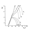
- FIG. 2 shows a characteristic field in which the ratio of the outlet-side pressure to the inlet-side pressure is plotted against the inlet-side volume flow.
- the diagram shows that with an angular adjustment of the guide vanes 5 with increasing angle, a shift of the position of the surge line shown in dash-dotted lines to the left can be achieved, the operating point characteristics being plotted for two peripheral speeds.
- the solid curve family is assigned to the lower peripheral speed and the dashed family of curves to the higher peripheral speed.
- the values of the volume flow plotted on the abscissa are relativized and plotted in percent, 100% being assigned to the volume flow occurring at the stuffing limit.
Landscapes
- Engineering & Computer Science (AREA)
- Mechanical Engineering (AREA)
- General Engineering & Computer Science (AREA)
- Supercharger (AREA)
- Control Of Turbines (AREA)
- Output Control And Ontrol Of Special Type Engine (AREA)
Abstract
Ein Axialdrallregler für einen Abgasturbolader für Verbrennungsmotoren hat einen Strömungskanal, welcher aus einem Zylinderabschnitt und einen daran anschließenden Kugelabschnitt besteht, der über einen Düsenabschnitt in einen zweiten zylindrischen Abschnitt übergeht. Der Radius des Kugelabschnitts ist gleich dem Radius des ersten Zylinderabschnittes. Die Leitschaufeln bestehen im wesentlichen aus Kreisausschnitten, die bei völliger Schließung des Leitapparates den Querschnitt des ersten Zylinderabschnittes überdecken, wobei die Drehachsen der Leitschaufeln jeweils in der Schaufeleintrittskante liegen.An axial swirl controller for an exhaust gas turbocharger for internal combustion engines has a flow channel, which consists of a cylinder section and an adjoining ball section which merges into a second cylindrical section via a nozzle section. The radius of the spherical section is equal to the radius of the first cylindrical section. The guide vanes essentially consist of circular sections which, when the guide apparatus is completely closed, cover the cross section of the first cylinder section, the axes of rotation of the guide vanes each lying in the blade leading edge.
Description
Die Erfindung betrifft einen Axialdrallregler für einen Abgasturbolader nach dem Oberbegriff des Anspruchs 1.The invention relates to an axial swirl controller for an exhaust gas turbocharger according to the preamble of
Abgasturbolader finden bei Verbrennungsmotoren Verwendung, um Leistung und Drehmoment bei günstigem Kraftstoffverbrauch zu erhöhen. Da Turbolader mit einem Radialverdichter aufgrund ihrer Druck-Volumen-Charakteristik nicht in der Lage sind, den gesamten Betriebsbereich der Verbrennungsmotoren zu überdecken, können sich einerseits bei niederer Motordrehzahl und einem Vollastbetrieb Betriebszustände einstellen, die links von der Pump- bzw. Abreißgrenze des Verdichterkennfeldes und andererseits bei hohen Motordrehzahlen und Vollastbetrieb rechts von der Stopfgrenze des Verdichterkennfeldes liegen. Aus diesem Grund ist es üblich, Turbolader derart auszulegen, daß die Pump- bzw. Abreißgrenze bei niederen Motordrehzahlen sowie einem Teillast- bzw. Vollastbetrieb nicht nach links überschritten wird. Für die Regelung dieses Betriebsverhaltens sind auf der Turbinenseite Bypass-Ventile bekannt, z.B. durch die DE-OS 14 26 076, mit deren Hilfe ein Teil des Abgasstromes um die Turbine herumgeführt werden kann, um bei Vollast und hoher Drehzahl hohe Ladedrücke zu vermeiden. Bei dieser Regelung geht ein Teil der Abgasenergie ungenutzt verloren.Exhaust gas turbochargers are used in internal combustion engines to increase power and torque with low fuel consumption. Since turbochargers with a radial compressor are not able to cover the entire operating range of the internal combustion engines due to their pressure-volume characteristics, operating conditions can occur on the one hand at low engine speed and at full load, which are to the left of the pumping or tear-off limit of the compressor map and on the other hand, at high engine speeds and full load operation, they are to the right of the stuffing limit of the compressor map. For this reason, it is customary to design turbochargers in such a way that the pumping or tear-off limit is not exceeded to the left at low engine speeds and at part-load or full-load operation. Bypass valves are known on the turbine side for controlling this operating behavior, e.g. through DE-OS 14 26 076, with the help of which part of the exhaust gas flow can be passed around the turbine in order to avoid high boost pressures at full load and high speed. With this regulation, part of the exhaust gas energy is lost unused.
Eine andere turbinenseitige Regelung wird durch einen verstellbaren Düsenkranz gemäß der DE-OS 24 55 361 realisiert, wobei das Abgas besser ausgenutzt werden kann.Another regulation on the turbine side is realized by an adjustable nozzle ring according to DE-OS 24 55 361, whereby the exhaust gas can be better utilized.
Generell aber beeinflussen turbinenseitige Regelungen für Turbolader nur die Leistung bzw. das Drehmoment. Sie sind geeignet, den augenblicklichen Leistungsbedarf des Verdichters innerhalb der durch die verfügbare Abgasmenge und Abgastemperatur gegebenen Grenzen den Erfordernissen anzupassen. Sie verändern dabei den Massenstrom, nicht jedoch das Verdichterkennfeld. Als Folge davon ist es durchaus möglich, daß der Verdichterbetriebspunkt aus dem Bereich guten Wirkungsgrades herauswandert oder gar in den Pumpbereich geraten kann.In general, however, turbine-side regulations for turbochargers only affect the output or the torque. They are suitable for adapting the instantaneous power requirement of the compressor to the requirements within the limits given by the available exhaust gas quantity and exhaust gas temperature. They change the mass flow, but not the compressor map. As a result, it is quite possible that the compressor operating point may move out of the area of good efficiency or even get into the pumping area.
Durch die DE-OS 14 26 076 ist auch eine verdichterseitige Turboladerregelung bekannt, wobei mittels einer Drosselklappe im Saugbereich der Volumenstrom reduziert, ja sogar ganz unterbunden werden kann. Eine Unterbindung des Volumenstroms kann wünschenswert sein, um bei einer vorübergehenden Entlastung des Motors, z.B. beim Auskuppeln, dafür zu sorgen, daß der Verdichter keine Leistung mehr aufnimmt und der Turboladerrotor nicht zu stark in der Drehzahl absinkt. Mit dieser verdichterseitigen Turboladerregelung ist eine Veränderung der nutzbaren Kennfeldbreite jedoch nicht möglich.A compressor-side turbocharger control is also known from DE-OS 14 26 076, wherein the volume flow can be reduced or even completely prevented by means of a throttle valve in the suction area. It may be desirable to prevent the volume flow in order to relieve the motor temporarily, e.g. when disengaging, ensure that the compressor no longer consumes power and the turbocharger rotor does not drop too much in speed. With this compressor-side turbocharger control, however, it is not possible to change the usable map width.
Durch die DE-AS 16 28 232 ist ein Axialdrallregler für Verdichter mit größeren Abmessungen bekannt, mit welchem eine Kennlinienverschiebung möglich ist. Bei diesem Axialdrallregler besteht der Strömungskanal, in welchem die Leitschaufeln des axialen Leitapparates angeordnet sind, aus zwei zylindrischen Mantelabschnitten mit nur geringfügig verschiedenen Durchmessern und einem dazwischen liegenden Kugelabschnitt, bei welchem der Kugelradius größer als der Radius des größeren zylindrischen Mantelabschnittes ist, d.h., der Strömungskanal erfährt im Bereich der Leitschaufeln eine Durchmesservergrößerung. Diese Durchmesservergrößerung im Strömungskanal führt zu einer Strömungsablösung und zu einer Vergrößerung der durch einen Geschwindigkeitssprung an den Leitschaufeln ausgelösten Wirbelschleppe. Da der verdichterseitig an den Kugelabschnitt anschließende zylindrische Mantelabschnitt einen nur unwesentlich kleineren Durchmesser als der erste zylindrische Mantelabschnitt hat, ist eine rasche Unterdrückung der Störung der Strömung vor dem Eintritt in den Verdichter nicht möglich.From DE-AS 16 28 232 an axial swirl controller for compressors with larger dimensions is known, with which a characteristic curve shift is possible. In this axial swirl controller, the flow channel, in which the guide vanes of the axial guide apparatus are arranged, consists of two cylindrical jacket sections with only slightly different diameters and an intermediate ball section, in which the ball radius is larger than the radius of the larger cylindrical jacket section, i.e. the flow channel experiences an increase in diameter in the area of the guide vanes. This increase in diameter in the flow channel leads to a separation of the flow and to an increase in the vortex wake triggered by a speed jump on the guide vanes. Since the cylindrical casing section adjoining the spherical section on the compressor side has only an insignificantly smaller diameter than the first cylindrical casing section, rapid suppression of the disturbance of the flow before entering the compressor is not possible.
Der Erfindung liegt die Aufgabe zugrunde, einen Axialdrallregler für einen Turbolader zu schaffen, mit dem der Vertriebsbereich des Verbrennungsmotors bei bestem Wirkungsgrad bzw. günstigem Kraftstoffverbrauch noch weiter erweitert werden kann. Insbesondere sollen bei jeder Motordrehzahl sowohl bei Vollast als auch bei Teillast diese optimalen Betriebsbereiche schnell und ökonomisch erreicht werden, das heißt, auch extreme Betriebszustände und deren plötzliche Änderungen wirtschaftlich gefahren werden können. Der nutzbare Regelbereich muß so breit und das Verdichterkennfeld so verschiebbar ausgelegt sein, daß der jeweilige Betriebspunkt im Bereich des besten Wirkungsgrades liegt und die Pumpgrenze durch die Verschiebung des Kennlinienfeldes den jeweiligen Betriebspunkt nicht tangiert.The invention has for its object to provide an axial swirl controller for a turbocharger, with which the sales area of the internal combustion engine is further expanded with the best efficiency and low fuel consumption can be. In particular, at any engine speed, both at full load and at partial load, these optimal operating ranges should be reached quickly and economically, which means that extreme operating states and their sudden changes can also be operated economically. The usable control range must be so wide and the compressor map must be designed so that the respective operating point is in the range of the best efficiency and the surge limit does not affect the respective operating point due to the shifting of the characteristic field.
Diese Aufgabe wird durch die die Erfindung im Anspruch 1 kennzeichnenden Merkmale gelöst.This object is achieved by the features characterizing the invention in
Durch die Maßnahmen der Erfindung wird erreicht, daß hinter den schwenkbaren Leitschaufeln der an den Kugelabschnitt anschließende zweizylindrische Abschnitt einen wesentlich kleineren Radius hat und damit die Verkleinerung des Querschnitt des Strömungskanals eine beschleunigte Düsenströmung erzeugt, wodurch die Nachlaufstörungen der Leitschaufeln, und insbesondere die durch den Grenzschichteffekt ausgelösten Nachlaufdellen, rasch unterdrückt werden und eine gesunde, gleichmäßige Zuströmung zum Verdichterlaufrad gewährleistet wird.The measures of the invention ensure that behind the pivotable guide vanes, the two-cylindrical section adjoining the spherical section has a substantially smaller radius, and thus the reduction in the cross section of the flow channel produces an accelerated nozzle flow, as a result of which the guide vanes malfunction, and in particular those caused by the boundary layer effect triggered dents, are quickly suppressed and a healthy, even inflow to the compressor impeller is guaranteed.
Dadurch kann man erreichen, daß durch eine Verstellung der Leitschaufeln die Pumpgrenze so weit nach links verschoben wird, daß die in Abhängigkeit von der Motorbelastung, dem Kraftstoffbedarf und der Motordrehzahl erforderliche Ladeluftmenge und der erforderliche Ladeluftdruck auch bei extremen Betriebszuständen und deren plötzlichen Anderung zur Verfügung stehen, wobei das Kennlinienfeld so verschoben ist, daß der Betriebsdruck immer rechts von der Pumpgrenze liegt.This can be achieved that by adjusting the guide vanes, the surge limit is shifted so far to the left that the amount of charge air and the required charge air pressure, which are dependent on the engine load, the fuel requirement and the engine speed, are available even in extreme operating conditions and their sudden change , whereby the characteristic field is shifted so that the operating pressure is always to the right of the surge limit.
Weitere Ausgestaltungen der Erfindung sind Gegenstand von Unteransprüchen.Further embodiments of the invention are the subject of dependent claims.
Für die vorteilhafte Wirkung der Erfindung haben sich Verhältnisse der Durchmesser vom ersten Zylinderabschnitt zum zweiten Zylinderabschnitt zwischen 1,4 und 1,6 und vorzugsweise zwischen 1,45 und 1,5 als besonders zweckmäßig erwiesen, wobei die Maßnahmen der Erfindung die Möglichkeit bieten, auch bei den heutzutage im Kraftfahrzeugbau verwendeten Turboladern mit sehr kleinen Verdichterraddurchmessern dafür zu sorgen, daß optimale Betriebsbedingungen im gesamten Motorbetriebsbereich möglich sind.For the advantageous effect of the invention, ratios of the diameters from the first cylinder section to the second cylinder section between 1.4 and 1.6 and preferably between 1.45 and 1.5 have proven to be particularly expedient, the measures of the invention also offering the possibility in the turbochargers used today in motor vehicle construction with very small compressor wheel diameters to ensure that optimal operating conditions are possible in the entire engine operating range.
Bei den geringen Abmessungen der für den Kraftfahrzeugbereich üblichen Turbolader - wobei der erste zylindrische Mantelabschnitt bei Standardturboladern im Bereich von 60 mm und kleiner liegen kann - ist es besonders wichtig, dafür Sorge zu tragen, daß die unvermeidlichen Fertigungstoleranzen, die sich bei den kleinen absoluten Abmessungen beim Zusammenbau verhältnismäßig stark auswirken, die Funktionsweise nicht stören. Daher sieht die Erfindung Maßnahmen vor, daß der Leitapparat so zusammenbaubar ist, daß eine einwandfreie Einstellung ohne Klemmen möglich wird, und daß erst danach durch eine kraftschlüssige Verschraubung die Fixierung erfolgt. Zu diesem Zweck ist vorgesehen, daß die Wellen der Drehachsen der Leitschaufeln im Gehäuse wälzgelagert sind und außerhalb des Gehäuses die Verstellhebel tragen, und daß die Leitschaufeln, das Wälzlager und die Verstellhebel kraftschlüssig verspannt sind. Ferner ist vorgesehen, daß das freie Ende der Verstellhebel einen Kugelzapfen trägt, der in einer zur Laderachse parallelen Nut in dem Verstellring geführt ist, wobei der Verstellring konzentrisch zur Laderachse auf dem Außenumfang des Gehäuses auf einer zylindrischen Ringfläche gelagert ist. Dieses Lager ist vorzugsweise ein Nadellager.With the small dimensions of the turbochargers customary for the motor vehicle sector - the first cylindrical jacket section for standard turbochargers being in the range of 60 mm and smaller - it is particularly important to ensure that the inevitable manufacturing tolerances resulting from the small absolute dimensions impact relatively strongly during assembly, do not interfere with the functionality. Therefore, the invention provides measures that the diffuser can be assembled so that a perfect setting without jamming is possible, and that the fixation takes place only afterwards by a force-fitting screw connection. For this purpose, it is provided that the shafts of the axes of rotation of the guide vanes are roller-mounted in the housing and carry the adjusting lever outside the housing, and that the guide vanes, the roller bearing and the adjusting lever are non-positively clamped. It is further provided that the free end of the adjusting lever carries a ball pin which is guided in a groove in the adjusting ring which is parallel to the loader axis, the adjusting ring being mounted concentrically to the loader axis on the outer circumference of the housing on a cylindrical annular surface. This bearing is preferably a needle bearing.
Die Vorteile und Merkmale der Erfindung ergeben sich auch aus der nachfolgenden Beschreibung eines Ausführungsbeispieles in Verbindung mit den Ansprüchen und der Zeichnung. Es zeigen:
- Fig.1 einen Schnitt durch einen an einem Deckel eines Verdichtergehäuses montierten Axialdrallregler;
- Fig.2 ein Kennlinienfeld, aus welchem die Verschiebung der Pumpgrenze in Abhängigkeit von der Schaufelstellung für zwei Umfangsgeschwindigkeiten dargestellt ist;
- 1 shows a section through an axial swirl regulator mounted on a cover of a compressor housing;
- 2 shows a characteristic field from which the displacement of the surge limit as a function of the blade position for two circumferential speeds is shown;
Der in Fig. 1 dargestellte und auf dem Spiralgehäuse des Verdichters eines Turboladers für Verbrennungsmotoren montierte Axialdrallregler 1 besteht aus einem Gehäuse 6, in dessen Innern der Strömungskanal verläuft, in welchem ein Leitapparat 2 mit verstellbaren Leitschaufeln 5 angeordnet ist. Der Strömungskanal hat einen ersten Zylinderabschnitt 9, der sich vor dem Leitapparat 2 erstreckt und in einen Kugelabschnitt 10 übergeht, dessen Kugelradius gleich dem Radius des ersten Zylinderabschnittes 9 ist. An den Kugelabschnitt 10 schließt ein zweiter Zylinderabschnitt 11 an, dessen Durchmesser wesentlich kleiner als der erste Zylinderabschnitt 9 ist und in welchen der Kugelabschnitt mit einem als Düsenabschnitt 12 ausgebildeten Teil übergeht. Ein Diffusorabschnitt, in welchem sich das Verdichterrad dreht, schließt an den zweiten Zylinderabschnitt 11 an.The
Der Leitapparat 2 besteht aus einem Kranz von Leitschaufeln 5, welche sich über den Querschnitt des Strömungskanals erstrecken und im wesentlichen einen Kreisausschnitt von solcher Form und Teilung haben, daß die Leitschaufeln 5 bei völliger Schließung des Leitapparates 2 den Querschnitt des Strömungskanals fast ganz überdecken. In der Darstellung gemäß Fig. 1 ist lediglich eine Leitschaufel 5 dargestellt.The
Die Drehachse der einzelnen Leitschaufeln 5 verläuft jeweils in der Schaufeleintrittskante, so daß die nach außen ragende Welle der Leitschaufeln in der Verlängerung der Eintrittskante verläuft. Im Bereich der Ebene der Drehachse beginnt der Kugelabschnitt 10, der - wie bereits erwähnt - einen dem Radius des ersten Zylinderabschnittes 9 entsprechenden Kugelradius hat. Die Basis der Leitschaufeln verläuft ebenfalls kreisbogenförmig mit einem Radius, der dem Kugelradius entspricht, so daß sich bei dem Verschwenken der Leitschaufeln eine gleichbleibende, gleichmäßige Spaltbreite für alle Winkelstellungen ergibt und die Hinterkante der Leitschaufel der Kanalkontur folgt. Die Welle der Leitschaufeln 5 ist im Gehäuse 6 mit einem Wälzlager 13 gelagert und trägt auf dem außerhalb des Gehäuses 6 befindlichen Abschnitt einen Verstellhebel 14, dessen freies Ende mit einem radial nach innen weisenden Kugelzapfen 16 versehen ist. Die jeweilige Leitschaufel 5 und das dazugehörige Wälzlager sowie der dazugehörige Verstellhebel 14 werden mit Hilfe einer Schraubenmutter 15 kraftschlüssig gegeneinander verspannt. Das Wälzlager 13 ist in einer auf der Außenseite des Gehäuses 6 angebrachten Buchse fixiert. Im Bereich neben der Buchse ist das Gehäuse konzentrisch zur Laderachse 3 mit einer zylindrischen Ringfläche 19 versehen, auf der ein Verstellring 18 mit Hilfe eines Nadellagers 20 gehaltert und gelagert ist. Der Verstellring ist auf seiner Außenseite mit zur Laderachse parallel verlaufenden Nuten 17 versehen, in welche die Kugelzapfen 16 eingreifen. Durch Drehen des Verstellringes kann somit über die Verstellhebel 14 der Leitschaufelkranz in der gewünschten Weise winkelverstellt werden, um den Drall der Strömung zu beeinflussen. Da die absoluten Abmessungen aufgrund der Größe des Turboladers verhältnismäßig klein sind und infolgedessen die unvermeidlichen Toleranzen beim Zusammenbau verhältnismäßig stark wirksam sind, werden die jeweilige Leitschaufel, das Wälzlager und der dazugehörige Verstellhebel zunächst ohne-Verklemmen bzw. Verspannen zusammengebaut und die erforderlichen Verstellpositionierungen vorgenommen, bevor die Schraubmutter 15 angezogen wird, um die einzelnen Teile in der genau positionierten Lage kraftschlüssig zu verspannen. Bei der Verwendung einer formschlüssigen Verspannung wäre wegen der unvermeidlichen Fertigungstoleranzen eine genaue Positionierung äußerst schwierig.The axis of rotation of the
Im Interesse einer optimalen Regelung auch bei extremen Betriebszuständen und deren plötzlichen Anderung muß dafür gesorgt werden, daß - wie bereits erwähnt - Nachlaufstörungen an den Leitschaufeln möglichst rasch unterdrückt und ausgeglichen werden. Dies geschieht durch die Beschleunigung der Strömung im Bereich des Düsenabschnittes 12, wobei durch die Verjüngung des Querschnittes die gewünschte Strömungsbeschleunigung erzielt wird. Als besonders vorteilhaft hat sich für die Verjüngung ein Durchmesserverhältnis Dl/D2 von etwa 1,4 bis etwa 1,6 ergeben. Vorzugsweise liegt dieses Verhältnis zwischen 1,45 und 1,5, wobei die Anzahl der Leitschaufeln für Unterschiede in den Verhältniswerten ausschlaggebend sein kann. Es hat sich gezeigt, daß mit einem Leitapparat, bestehend aus 5 bis 14 Leitschaufeln die gewünschte Verschiebung des Kennlinienfeldes zur Optimierung des Motorbetriebs auch bei extremen Betriebszuständen erzielbar ist.In the interest of optimal control even in extreme operating conditions and their sudden change, it must be ensured that - as already mentioned - run-on faults on the guide vanes are suppressed and compensated for as quickly as possible. This is done by accelerating the flow in the area of the
Aus Fig. 2 geht ein Kennlinienfeld hervor, bei dem das Verhältnis des ausgangsseitigen Druckes zum eingangsseitigen Druck über dem eingangsseitigen Volumenstrom aufgezeichnet ist. Das Diagramm läßt erkennen, daß sich bei einer Winkelverstellung der Leitschaufeln 5 mit zunehmendem Winkel eine Verschiebung der strichpunktiert dargestellten Lage der Pumpgrenze nach links erzielen läßt, wobei die Betriebspunktkennlinien für zwei Umfangsgeschwindigkeiten eingezeichnet sind. Die ausgezogene Kurvenschar ist der niederen Umfangsgeschwindigkeit und die gestrichelte Kurvenschar der höheren Umfangsgeschwindigkeit zugeordnet. Die auf der Abszisse aufgetragenen Werte des Volumenstroms sind relativiert und in Prozent aufgetragen, wobei 100% dem an der Stopfgrenze auftretenden Volumenstrom zugeordnet ist.2 shows a characteristic field in which the ratio of the outlet-side pressure to the inlet-side pressure is plotted against the inlet-side volume flow. The diagram shows that with an angular adjustment of the guide vanes 5 with increasing angle, a shift of the position of the surge line shown in dash-dotted lines to the left can be achieved, the operating point characteristics being plotted for two peripheral speeds. The solid curve family is assigned to the lower peripheral speed and the dashed family of curves to the higher peripheral speed. The values of the volume flow plotted on the abscissa are relativized and plotted in percent, 100% being assigned to the volume flow occurring at the stuffing limit.
Claims (10)
dadurch gekennzeichnet ,
characterized ,
dadurch gekennzeichnet ,
daß der Kugelabschnitt (10) im Gehäuse (6) den ganzen Schaufelbereich umschließt.2. axial swirl controller according to claim 1,
characterized ,
that the ball section (10) in the housing (6) encloses the entire blade area.
dadurch gekennzeichnet,
daß der Ubergang des Gehäusemantels vom ersten Zylinderabschnitt (9) zum Kugelabschnitt (10) in der Ebene der Drehachsen (4) der Leitschaufeln (5) liegt.3. axial swirl controller according to claim 1 or 2,
characterized,
that the transition of the housing shell from the first cylinder section (9) to the ball section (10) lies in the plane of the axes of rotation (4) of the guide vanes (5).
dadurch gekennzeichnet,
daß das Verhältnis der Durchmesser vom ersten Zylinderabschnitt (9) zum zweiten Zylinderabschnitt (11) zwischen 1,4 und 1,6 und vorzugsweise zwischen 1,45 und 1,5 liegt.4. axial swirl controller according to one of claims 1 to 3,
characterized,
that the ratio of the diameter of the first cylinder section (9) to the second cylinder section (11) is between 1.4 and 1.6 and preferably between 1.45 and 1.5.
dadurch gekennzeichnet,
characterized,
dadurch gekennzeichnet ,
daß das freie Ende der Verstellhebel (14) einen Kugelzapfen (16) hat, der in einer zur Ladeachse parallelen Nut (17) in dem Verstellring (18) geführt ist.6. axial swirl controller according to claim 5,
characterized ,
that the free end of the adjusting lever (14) has a ball pin (16) which is guided in a groove (17) parallel to the loading axis in the adjusting ring (18).
dadurch gekennzeichnet ,
daß der Verstellring (18) auf einer konzentrisch zur Ladeachse (3) auf dem Außenumfang des Gehäuses befindlichen zylindrischen Ringfläche (19) gelagert ist.7. axial swirl controller according to claim 6,
characterized ,
that the adjusting ring (18) is mounted on a cylindrical ring surface (19) concentric with the loading axis (3) on the outer circumference of the housing.
dadurch gekennzeichnet ,
daß die Lagerung für den Verstellring (18) ein Nadellager (20) ist.8. axial swirl controller according to claim 7,
characterized ,
that the bearing for the adjusting ring (18) is a needle bearing (20).
dadurch gekennzeichnet,
daß die Leitschaufelverstellung Endbegrenzungen aufweist.9. axial swirl controller according to claim 1 to 8,
characterized,
that the guide vane adjustment has end limits.
dadurch gekennzeichnet ,
daß das äußere Ende einer der Leitschaufelwellen ein Potentiometer (21) zum elektrischen Abgreifen der Schaufelanstellung trägt.10. axial swirl controller according to claims 1 to 9,
characterized ,
that the outer end of one of the guide vane shafts carries a potentiometer (21) for electrically tapping the vane position.
Priority Applications (1)
| Application Number | Priority Date | Filing Date | Title |
|---|---|---|---|
| AT87102412T ATE63980T1 (en) | 1986-04-24 | 1987-02-20 | AXIAL SPIN REGULATOR FOR AN EXHAUST GAS TURBOCHARGER FOR COMBUSTION ENGINES. |
Applications Claiming Priority (2)
| Application Number | Priority Date | Filing Date | Title |
|---|---|---|---|
| DE3613857 | 1986-04-24 | ||
| DE19863613857 DE3613857A1 (en) | 1986-04-24 | 1986-04-24 | AXIAL SWIRL CONTROLLER FOR EXHAUST GAS TURBOCHARGER FOR COMBUSTION ENGINES |
Publications (3)
| Publication Number | Publication Date |
|---|---|
| EP0243596A2 true EP0243596A2 (en) | 1987-11-04 |
| EP0243596A3 EP0243596A3 (en) | 1988-07-20 |
| EP0243596B1 EP0243596B1 (en) | 1991-05-29 |
Family
ID=6299424
Family Applications (1)
| Application Number | Title | Priority Date | Filing Date |
|---|---|---|---|
| EP87102412A Expired - Lifetime EP0243596B1 (en) | 1986-04-24 | 1987-02-20 | Axial drag regulator for an exhaust turbo charger for internal-combustion engines |
Country Status (5)
| Country | Link |
|---|---|
| US (1) | US4780055A (en) |
| EP (1) | EP0243596B1 (en) |
| AT (1) | ATE63980T1 (en) |
| DE (2) | DE3613857A1 (en) |
| ES (1) | ES2022821B3 (en) |
Cited By (4)
| Publication number | Priority date | Publication date | Assignee | Title |
|---|---|---|---|---|
| EP0439757A1 (en) * | 1990-01-29 | 1991-08-07 | A.G. Kühnle, Kopp & Kausch | Axial swirl controller for large capacity radial compressor |
| US7520717B2 (en) | 2004-09-01 | 2009-04-21 | Ford Global Technologies, Llc | Swirl generator for a radial compressor |
| US9249687B2 (en) | 2010-10-27 | 2016-02-02 | General Electric Company | Turbine exhaust diffusion system and method |
| CN110685797A (en) * | 2018-07-05 | 2020-01-14 | 大众汽车有限公司 | Method and internal combustion engine for operating an internal combustion engine |
Families Citing this family (21)
| Publication number | Priority date | Publication date | Assignee | Title |
|---|---|---|---|---|
| US5025629A (en) * | 1989-03-20 | 1991-06-25 | Woollenweber William E | High pressure ratio turbocharger |
| DE4117025A1 (en) * | 1991-05-24 | 1992-11-26 | Halberg Maschbau Gmbh & Co | SWIRL REGULATOR FOR CENTRIFUGAL PUMPS |
| US6012897A (en) * | 1997-06-23 | 2000-01-11 | Carrier Corporation | Free rotor stabilization |
| FR2849905B1 (en) * | 2003-01-15 | 2007-01-05 | Renault Sa | AIR SUPPLYING DEVICE OF THE COMPRESSOR OF A SUPERIOR THERMAL ENGINE |
| EP1574684A1 (en) * | 2004-03-12 | 2005-09-14 | ABB Turbo Systems AG | Control system and method for operating an exhaust gas turbocharger |
| DE102004039299A1 (en) * | 2004-08-13 | 2006-02-23 | Fev Motorentechnik Gmbh | Turbo compressor for internal combustion engine, has adjustable inlet turning device provided in area of compressor inlet, where inlet turning device has load-controlled device for tangential supply of intake air to compressor wheel |
| DE102005017975A1 (en) * | 2005-04-19 | 2006-11-02 | Audi Ag | Radial compressor arrangement for supercharger, has spiral guide vanes formed within housing to guide fluid medium flow with minimal effect on its high flow rates or high volume throughputs |
| DE102005019896B4 (en) * | 2005-04-29 | 2013-07-11 | Bayerische Motoren Werke Aktiengesellschaft | Swirler |
| EP1719887A1 (en) * | 2005-05-04 | 2006-11-08 | ABB Turbo Systems AG | Charging control of a combustion engine |
| DE102005045194B4 (en) * | 2005-09-21 | 2016-06-09 | Fev Gmbh | Guide for a turbo compressor of an internal combustion engine |
| GB0716060D0 (en) * | 2007-08-17 | 2007-09-26 | Cummins Turbo Technologies | An engine generator set |
| DE102008046220A1 (en) * | 2008-09-08 | 2010-03-11 | Bosch Mahle Turbo Systems Gmbh & Co. Kg | Swirl producing device for use in exhaust gas turbocharger in internal-combustion engine of motor vehicle, has guide vane movably arranged with respect to vane length that extends in radial and/or transverse directions in flow channel |
| GB0821089D0 (en) * | 2008-11-19 | 2008-12-24 | Ford Global Tech Llc | A method for improving the performance of a radial compressor |
| US20110088379A1 (en) * | 2009-10-15 | 2011-04-21 | General Electric Company | Exhaust gas diffuser |
| SG2014008791A (en) * | 2011-11-18 | 2014-04-28 | Halliburton Energy Services Inc | Autonomous fluid control system having a fluid diode |
| DE102013018368B4 (en) | 2013-11-02 | 2016-06-02 | Iav Gmbh Ingenieurgesellschaft Auto Und Verkehr | Adjustable swirl generating device for compressors |
| DE102014212606B4 (en) * | 2014-06-30 | 2020-12-17 | Ford Global Technologies, Llc | Motor vehicle and air filter box |
| JP6001707B2 (en) * | 2015-02-25 | 2016-10-05 | 株式会社オティックス | Compressor housing for turbocharger |
| US20170152860A1 (en) * | 2015-11-30 | 2017-06-01 | Borgwarner Inc. | Compressor inlet guide vanes |
| DE102017222209A1 (en) * | 2017-12-07 | 2019-06-13 | MTU Aero Engines AG | Guide vane connection and turbomachine |
| CN116971847A (en) * | 2023-07-28 | 2023-10-31 | 中国航发动力股份有限公司 | A replacement device and method for an engine high and low pressure adjustable guide vane actuator |
Citations (2)
| Publication number | Priority date | Publication date | Assignee | Title |
|---|---|---|---|---|
| US1978128A (en) | 1932-03-14 | 1934-10-23 | Clarage Fan Company | Vortex control |
| DE1503658A1 (en) | 1963-05-15 | 1970-02-19 | Westinghouse Electric Corp | Centrifugal compressor, especially for cooling units |
Family Cites Families (13)
| Publication number | Priority date | Publication date | Assignee | Title |
|---|---|---|---|---|
| US2412365A (en) * | 1943-10-26 | 1946-12-10 | Wright Aeronautical Corp | Variable turbine nozzle |
| US2606713A (en) * | 1948-04-26 | 1952-08-12 | Snecma | Adjustable inlet device for compressors |
| GB755527A (en) * | 1953-10-15 | 1956-08-22 | Power Jets Res & Dev Ltd | Mounting of swivelling guide vane elements in axial flow elastic fluid turbines |
| US2817475A (en) * | 1954-01-22 | 1957-12-24 | Trane Co | Centrifugal compressor and method of controlling the same |
| US2827224A (en) * | 1955-06-30 | 1958-03-18 | Buffalo Forge Co | Inlet vane actuating device |
| CH371857A (en) * | 1959-10-20 | 1963-09-15 | Bbc Brown Boveri & Cie | Blade adjustment device on turbo machine |
| US3089679A (en) * | 1960-06-06 | 1963-05-14 | Chrysler Corp | Gas turbine nozzle suspension and adjustment |
| US3096785A (en) * | 1960-06-27 | 1963-07-09 | Ingersoll Rand Co | Pipe line pump |
| US3195805A (en) * | 1961-10-25 | 1965-07-20 | Garrett Corp | Turbocharger differential pressure control |
| US3362625A (en) * | 1966-09-06 | 1968-01-09 | Carrier Corp | Centrifugal gas compressor |
| JPS58167825A (en) * | 1982-03-29 | 1983-10-04 | Hino Motors Ltd | Turbosupercharger device of vehicle engine |
| JPS58167824A (en) * | 1982-03-29 | 1983-10-04 | Hino Motors Ltd | Turbosupercharger device of vehicle engine |
| JPS58185934A (en) * | 1982-04-24 | 1983-10-29 | Hino Motors Ltd | Turbo supercharging device for car engine |
-
1986
- 1986-04-24 DE DE19863613857 patent/DE3613857A1/en active Granted
-
1987
- 1987-02-20 ES ES87102412T patent/ES2022821B3/en not_active Expired - Lifetime
- 1987-02-20 AT AT87102412T patent/ATE63980T1/en active
- 1987-02-20 EP EP87102412A patent/EP0243596B1/en not_active Expired - Lifetime
- 1987-02-20 DE DE8787102412T patent/DE3770327D1/en not_active Expired - Lifetime
- 1987-04-23 US US07/041,844 patent/US4780055A/en not_active Expired - Fee Related
Patent Citations (2)
| Publication number | Priority date | Publication date | Assignee | Title |
|---|---|---|---|---|
| US1978128A (en) | 1932-03-14 | 1934-10-23 | Clarage Fan Company | Vortex control |
| DE1503658A1 (en) | 1963-05-15 | 1970-02-19 | Westinghouse Electric Corp | Centrifugal compressor, especially for cooling units |
Cited By (6)
| Publication number | Priority date | Publication date | Assignee | Title |
|---|---|---|---|---|
| EP0439757A1 (en) * | 1990-01-29 | 1991-08-07 | A.G. Kühnle, Kopp & Kausch | Axial swirl controller for large capacity radial compressor |
| DE4002548A1 (en) * | 1990-01-29 | 1991-08-08 | Kuehnle Kopp Kausch Ag | Axial swirl flow control for large vol axial. flow compressor - has guide vane rotary axis dividing vanes in specified ratio in transition region |
| US7520717B2 (en) | 2004-09-01 | 2009-04-21 | Ford Global Technologies, Llc | Swirl generator for a radial compressor |
| US9249687B2 (en) | 2010-10-27 | 2016-02-02 | General Electric Company | Turbine exhaust diffusion system and method |
| CN110685797A (en) * | 2018-07-05 | 2020-01-14 | 大众汽车有限公司 | Method and internal combustion engine for operating an internal combustion engine |
| CN110685797B (en) * | 2018-07-05 | 2021-10-01 | 大众汽车有限公司 | Method and internal combustion engine for operating an internal combustion engine |
Also Published As
| Publication number | Publication date |
|---|---|
| ATE63980T1 (en) | 1991-06-15 |
| DE3613857A1 (en) | 1987-10-29 |
| ES2022821B3 (en) | 1991-12-16 |
| DE3613857C2 (en) | 1988-07-28 |
| EP0243596B1 (en) | 1991-05-29 |
| EP0243596A3 (en) | 1988-07-20 |
| DE3770327D1 (en) | 1991-07-04 |
| US4780055A (en) | 1988-10-25 |
Similar Documents
| Publication | Publication Date | Title |
|---|---|---|
| EP0243596B1 (en) | Axial drag regulator for an exhaust turbo charger for internal-combustion engines | |
| EP1488084B1 (en) | Variable exhaust gas turbocharger | |
| EP0433560B1 (en) | Exhaust gas turbocharger for an internal combustion engine | |
| EP0093462B1 (en) | Turbo charger with a sliding ring valve | |
| DE102018221812B4 (en) | Exhaust gas turbine with an exhaust gas guide device for an exhaust gas turbocharger and an exhaust gas turbocharger | |
| DE10336994B4 (en) | Internal combustion engine with supercharging and associated air compressor | |
| EP1710415A1 (en) | Multiple step turbocharging | |
| WO2006133838A1 (en) | Waste gas turbine in a waste gas turbocharger | |
| EP3682115B1 (en) | Compressor for a charging device of an internal combustion engine, and charging device for an internal combustion engine | |
| EP2147216A1 (en) | Exhaust gas turbocharger | |
| DE69402372T2 (en) | Inlet guide vane against whistling | |
| EP0086466B1 (en) | Through-flow arrangement for the volute inlet of a radial turbine | |
| WO2009130262A1 (en) | Carrier ring of a conducting device with sealing air channel | |
| DE102015006288A1 (en) | Turbine for an exhaust gas turbocharger, in particular an internal combustion engine, and drive device for a motor vehicle | |
| EP3056690B1 (en) | Centrifugal compressor, exhaust gas turbocharger and corresponding method for operating a centrifugal compressor | |
| DE102018211091B4 (en) | Method for operating an internal combustion engine and internal combustion engine | |
| DE102020202967A1 (en) | Exhaust gas turbocharger with integral housing | |
| DE102011111747A1 (en) | Compressor for exhaust turbocharger of internal combustion engine, particularly gasoline engine of motor vehicle, particularly passenger car, comprises guide element arranged against air flow in axial direction of compressor wheel | |
| DE102014220680A1 (en) | Internal combustion engine with mixed-flow turbine comprising a guide | |
| DE102005011482A1 (en) | Exhaust turbo charger has stator with three or more spaced blades whose end edges are at different angular spacing from one another to reduce resonance | |
| DE8611258U1 (en) | Axial swirl regulator for an exhaust gas turbocharger for internal combustion engines | |
| DE2948089A1 (en) | IC engine multistage exhaust gas turbocharger - has concentric by=pass duct round exhaust spiral feed, controlled by valves | |
| DE10217470A1 (en) | Exhaust turbine for variable turbocharger for engine brake operation of IC engines, with blade angle of turbine wheel blades varied so that turbine efficiency is smaller in nominal brake pint than the optimum | |
| DE102017210168A1 (en) | Turbine with variable turbine outlet and compressor with variable compressor inlet | |
| DE4210048A1 (en) | Exhaust gas turbocharger of an internal combustion engine |
Legal Events
| Date | Code | Title | Description |
|---|---|---|---|
| PUAI | Public reference made under article 153(3) epc to a published international application that has entered the european phase |
Free format text: ORIGINAL CODE: 0009012 |
|
| 17P | Request for examination filed |
Effective date: 19870318 |
|
| AK | Designated contracting states |
Kind code of ref document: A2 Designated state(s): AT CH DE ES FR GB IT LI |
|
| PUAL | Search report despatched |
Free format text: ORIGINAL CODE: 0009013 |
|
| AK | Designated contracting states |
Kind code of ref document: A3 Designated state(s): AT CH DE ES FR GB IT LI |
|
| 17Q | First examination report despatched |
Effective date: 19890913 |
|
| GRAA | (expected) grant |
Free format text: ORIGINAL CODE: 0009210 |
|
| AK | Designated contracting states |
Kind code of ref document: B1 Designated state(s): AT CH DE ES FR GB IT LI |
|
| REF | Corresponds to: |
Ref document number: 63980 Country of ref document: AT Date of ref document: 19910615 Kind code of ref document: T |
|
| ET | Fr: translation filed | ||
| GBT | Gb: translation of ep patent filed (gb section 77(6)(a)/1977) | ||
| REF | Corresponds to: |
Ref document number: 3770327 Country of ref document: DE Date of ref document: 19910704 |
|
| ITF | It: translation for a ep patent filed | ||
| PLBE | No opposition filed within time limit |
Free format text: ORIGINAL CODE: 0009261 |
|
| STAA | Information on the status of an ep patent application or granted ep patent |
Free format text: STATUS: NO OPPOSITION FILED WITHIN TIME LIMIT |
|
| 26N | No opposition filed | ||
| PGFP | Annual fee paid to national office [announced via postgrant information from national office to epo] |
Ref country code: GB Payment date: 19940131 Year of fee payment: 8 |
|
| PGFP | Annual fee paid to national office [announced via postgrant information from national office to epo] |
Ref country code: FR Payment date: 19940204 Year of fee payment: 8 |
|
| PGFP | Annual fee paid to national office [announced via postgrant information from national office to epo] |
Ref country code: AT Payment date: 19940211 Year of fee payment: 8 |
|
| PGFP | Annual fee paid to national office [announced via postgrant information from national office to epo] |
Ref country code: ES Payment date: 19940221 Year of fee payment: 8 |
|
| PGFP | Annual fee paid to national office [announced via postgrant information from national office to epo] |
Ref country code: CH Payment date: 19940311 Year of fee payment: 8 |
|
| PG25 | Lapsed in a contracting state [announced via postgrant information from national office to epo] |
Ref country code: GB Effective date: 19950220 Ref country code: AT Effective date: 19950220 |
|
| PG25 | Lapsed in a contracting state [announced via postgrant information from national office to epo] |
Ref country code: ES Free format text: LAPSE BECAUSE OF NON-PAYMENT OF DUE FEES Effective date: 19950221 |
|
| PG25 | Lapsed in a contracting state [announced via postgrant information from national office to epo] |
Ref country code: LI Effective date: 19950228 Ref country code: CH Effective date: 19950228 |
|
| GBPC | Gb: european patent ceased through non-payment of renewal fee |
Effective date: 19950220 |
|
| PG25 | Lapsed in a contracting state [announced via postgrant information from national office to epo] |
Ref country code: FR Effective date: 19951031 |
|
| REG | Reference to a national code |
Ref country code: FR Ref legal event code: ST |
|
| REG | Reference to a national code |
Ref country code: ES Ref legal event code: FD2A Effective date: 19990301 |
|
| PGFP | Annual fee paid to national office [announced via postgrant information from national office to epo] |
Ref country code: DE Payment date: 20040227 Year of fee payment: 18 |
|
| PG25 | Lapsed in a contracting state [announced via postgrant information from national office to epo] |
Ref country code: IT Free format text: LAPSE BECAUSE OF NON-PAYMENT OF DUE FEES Effective date: 20050220 |
|
| PG25 | Lapsed in a contracting state [announced via postgrant information from national office to epo] |
Ref country code: DE Free format text: LAPSE BECAUSE OF NON-PAYMENT OF DUE FEES Effective date: 20050901 |