EP0242945B1 - Akustische Vorrichtung zum Steuern des Verhaltens von Fischen - Google Patents
Akustische Vorrichtung zum Steuern des Verhaltens von Fischen Download PDFInfo
- Publication number
- EP0242945B1 EP0242945B1 EP87301164A EP87301164A EP0242945B1 EP 0242945 B1 EP0242945 B1 EP 0242945B1 EP 87301164 A EP87301164 A EP 87301164A EP 87301164 A EP87301164 A EP 87301164A EP 0242945 B1 EP0242945 B1 EP 0242945B1
- Authority
- EP
- European Patent Office
- Prior art keywords
- mass
- radiating surface
- actuator
- enclosure
- surface means
- Prior art date
- Legal status (The legal status is an assumption and is not a legal conclusion. Google has not performed a legal analysis and makes no representation as to the accuracy of the status listed.)
- Expired - Lifetime
Links
Images


Classifications
-
- A—HUMAN NECESSITIES
- A01—AGRICULTURE; FORESTRY; ANIMAL HUSBANDRY; HUNTING; TRAPPING; FISHING
- A01K—ANIMAL HUSBANDRY; AVICULTURE; APICULTURE; PISCICULTURE; FISHING; REARING OR BREEDING ANIMALS, NOT OTHERWISE PROVIDED FOR; NEW BREEDS OF ANIMALS
- A01K15/00—Devices for taming animals, e.g. nose-rings or hobbles; Devices for overturning animals in general; Training or exercising equipment; Covering boxes
- A01K15/02—Training or exercising equipment, e.g. mazes or labyrinths for animals ; Electric shock devices; Toys specially adapted for animals
-
- A—HUMAN NECESSITIES
- A01—AGRICULTURE; FORESTRY; ANIMAL HUSBANDRY; HUNTING; TRAPPING; FISHING
- A01K—ANIMAL HUSBANDRY; AVICULTURE; APICULTURE; PISCICULTURE; FISHING; REARING OR BREEDING ANIMALS, NOT OTHERWISE PROVIDED FOR; NEW BREEDS OF ANIMALS
- A01K79/00—Methods or means of catching fish in bulk not provided for in groups A01K69/00 - A01K77/00, e.g. fish pumps; Detection of fish; Whale fishery
- A01K79/02—Methods or means of catching fish in bulk not provided for in groups A01K69/00 - A01K77/00, e.g. fish pumps; Detection of fish; Whale fishery by electrocution
-
- G—PHYSICS
- G10—MUSICAL INSTRUMENTS; ACOUSTICS
- G10K—SOUND-PRODUCING DEVICES; METHODS OR DEVICES FOR PROTECTING AGAINST, OR FOR DAMPING, NOISE OR OTHER ACOUSTIC WAVES IN GENERAL; ACOUSTICS NOT OTHERWISE PROVIDED FOR
- G10K1/00—Devices in which sound is produced by striking a resonating body, e.g. bells, chimes or gongs
- G10K1/06—Devices in which sound is produced by striking a resonating body, e.g. bells, chimes or gongs the resonating devices having the shape of a bell, plate, rod, or tube
- G10K1/07—Devices in which sound is produced by striking a resonating body, e.g. bells, chimes or gongs the resonating devices having the shape of a bell, plate, rod, or tube mechanically operated; Hand bells; Bells for animals
- G10K1/072—Operating or striking mechanisms therefor
-
- G—PHYSICS
- G10—MUSICAL INSTRUMENTS; ACOUSTICS
- G10K—SOUND-PRODUCING DEVICES; METHODS OR DEVICES FOR PROTECTING AGAINST, OR FOR DAMPING, NOISE OR OTHER ACOUSTIC WAVES IN GENERAL; ACOUSTICS NOT OTHERWISE PROVIDED FOR
- G10K9/00—Devices in which sound is produced by vibrating a diaphragm or analogous element, e.g. fog horns, vehicle hooters or buzzers
- G10K9/10—Devices in which sound is produced by vibrating a diaphragm or analogous element, e.g. fog horns, vehicle hooters or buzzers driven by mechanical means only
Definitions
- the present invention relates to a device for eliciting a behavioural response in fish by means of sound.
- the device provides a non-lethal stimulus for fish and may be used to attract or repel fish.
- the use of the invention as a management tool for repelling fish has application at industrial and electric generating station intakes.
- the invention may be useful in the commercial fishing industry.
- Sound travels approximately 4.8 times faster in water than in air and consists of two components, namely a pressure wave and a particle velocity associated with the sinusoidal sound wave pattern. Both of these components are produced by the invention and can be perceived by the acoustical-lateralis system of a wide variety of fish.
- Sound is detected by fish using several mechanisms which may include the inner ear, swim bladder, lateral line and a skin sensory system.
- the swim bladder appears to be the most obvious and efficient sonic detector.
- Fish with swim bladders are expected to have a better hearing capability than those without.
- those species which have an auditory connection, e.g. Ostariophysi, from the swim bladder to the inner ear probably have the most sensitive hearing.
- Sound sensitivity of fish with open versus closed swim bladders is largely unknown.
- the lateral line is believed to be primarily a low frequency sound detector.
- non-ostariophysines appear to be generally within the 20-500 Hz range. This range is extended to higher frequencies for fish with weberian ossicles or similar apparatus (e.g. ostariophysines).
- prior devices were not capable of producing a significant amplitude or shock wave component of the sound generated to elicit a behavioural response in most fish.
- the requirement of a shock wave to elicit a marked response in fish was first suggested by Schuler and Larson (Schuler, V. J. and L. E. Larson (1975) Improved Fish Protection at Intakes, J. Environ. Eng. Div. , AECE Vol. 10:887-910).
- the ineffectiveness of various taped sounds such as rock music to act as a deterrent for fish was attributed by Schuler and Larson to the absence of a shock or pressure wave component to the sound.
- the present device is capable of producing significant sound pressures at different fundamental frequencies ranging from 20 to 1000 Hz. It is felt that it is the combination of suitable frequency and amplitude of the sound generated by the device which elicits a desired behavioural response in the fish.
- pneumatic guns such as the type used in seismic oil exploration. These devices provide a sudden release of high pressure air to produce a low frequency, high amplitude sound. While the use of pneumatic guns to elicit an avoidance response in fish has been shown to be effective at least with respect to certain fish species (see Haymes, G. T. and Patrick, P. H. (1984) Alternative Fish Protective Techniques; Pneumatic Guns and Rope Nets, ESEERCO EP 83-12), these guns suffer from a number of limitations which make them generally unsuitable for use in a permanent installation. The pneumatic guns are relatively expensive and require frequent maintenance and lubrication.
- Air leaks are a constant problem and are often difficult to locate when the system involves the use of an array of many guns. Also, the guns are limited in respect of the sound frequencies which can be generated by them. Since different species of fish may respond in the desired fashion to different frequencies of sound, it is important to be able to generate the appropriate sound signal in order to achieve the desired result.
- US-A-3317889 Another known device for eliciting a behavioural response in fish is disclosed in US-A-3317889.
- This known device comprises a submersible acoustic water tight enclosure, radiating surface means rigidly supported about its perimeter in a wall of the enclosure and defining a radiating surface and drive means within the enclosure which are capable of causing the radiating surface to vibrate at its resonant frequencies so that an acoustic signal is generated under water.
- Means are provided to selectively optimize the frequency of the acoustic signal.
- the present invention addresses the various requirements for sound generation to elicit a behavioural response in fish by providing a simple, low cost, low maintenance device.
- the device of the invention relies on the use of a mechanical or an electro-mechanical means for driving a radiator or radiating surface at one of its resonant frequencies to generate an acoustic signal having the desired frequency and amplitude characteristics.
- the radiator may be driven by a vibrator controlled by a signal generator so that a range of frequencies may be readily produced, and any such frequency may be produced at a relatively high sound pressure level for a desired period of time.
- the radiator is driven repetitively to produce a suitable acoustic signal impulse which is allowed to decay between repetitions.
- Each form of the invention may be used alone or in conjunction with the other form of the invention to achieve the desired behavioural response in targeted fish.
- repelling fish it is generally preferred to employ an array of devices of the invention about the area where fish are to be excluded in order to obtain the best results.
- the invention provides an underwater acoustic device for eliciting a behavioural response in fish as claimed in the ensuing claim 1.
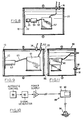
- one embodiment of the invention comprises an acoustic generator 10 anchored in place underwater by means of an anchor 12 or other similar means and a power supply 14 coupled with an automatic control 15.
- the acoustic generator 10 comprises a water tight enclosure preferably filled with air or other low impedance medium.
- the enclosure is provided with a radiating surface 16 and means for actuating a mass to impact the radiating surface 16 so as to generate a sound.
- a resonant acoustic signal may be produced under water by the generator 10.
- the generator 10 is designed to produce a peak sound pressure level of at least 0.5 kPa (0 to peak) at a distance of 3 meters from the radiating surface 16.
- FIG. 2 A typical amplitude profile of an acoustic signal generated in accordance with this embodiment of the invention as measured 3 meters from the radiating surface 16 is shown in Fig. 2.
- the peak pressure level P1 for each impulse of sound generated is attained within the first or second oscillation from signal initiation.
- the sound pressure level then decays at a rate dependent on the overall damping of the system.
- the signal is regenerated at a time T R after the initial impact of the mass against the radiating surface 16.
- Both the time T R between signals as well as the amplitude of the signals generated is governed by the automatic control 15. That is, the control 15 governs the repetition rate of the mass impacting the radiating surface 16 and in the case of the embodiments of Figures 8 and 9, the force of those impacts within the parameters of the components.
- the frequency content of a typical underwater signal generated by the device 10 is shown in Fig. 3.
- the fundamental frequency f0 is the frequency of the first natural mode of vibration of the dynamic system comprising the generator 10 and the surrounding water.
- the higher frequencies f1, f2, etc., shown in Fig. 3 are the natural modes of vibration of the system.
- the fundamental frequency normally has the highest magnitude, however, the invention provides for considerable variability in the frequencies and the relative magnitudes of the acoustic signals generated. This variability is achieved by using any of a variety of materials between the impacting mass and the radiating surface 16 of the generator 10.
- the generator 10 may be tuned both within a range of frequencies and amplitudes. This feature is important to enable use of the generator 10 to elicit a desired behavioural response in a wide variety of fish species.
- the acoustic signal generator 10 in accordance with this embodiment of the invention is illustrated in a number of variants in Figs. 4-9.
- the generator 10 comprises a water tight enclosure 2u which may conveniently be cylindrical having a volume of about 220 liters.
- a radiating surface 16 is rigidly supported about its perimeter in a wall of the enclosure 20.
- the radiating surface 16 is positioned in an end of the enclosure 20.
- a typical construction of a generator 10 comprises an 1/8 inch thick steel radiating surface 16 in an end of a steel cylindrical enclosure 20.
- a strike plate 22 may be attached, for example, by welding, to the radiating surface 16 for receiving the impact from a mass 25.
- the strike plate 22 serves to reinforce the radiating surface 16 and to spread the force load from the impacting mass 25.
- the strike plate 22 serves to reinforce the radiating surface 16 and to spread the force load from the impacting mass 25.
- surfaces 16 and plates 22 which may be used to generate acoustic signals having qualities which elicit a behavioral response in fish.
- a drive means for the radiating surface 16 is provided in the device of Fig. 4 by a mass 25.
- the mass 25 is caused to move along a rail 27 to impact a strike plate 22 or the surface 16 directly under the influence of a spring 28.
- the mass 25 is drawn back from the strike plate 22 by a rotary actuator 30 having a clutch means for disengaging the actuator drive.
- the mass 25 is attached to the rotary actuator 30 by a cable or chain 31 which may pass over a pulley or sprocket 32 attached to the rear wall 33 of the enclosure 20.
- the actuator 30 causes the cable 31 to be reeled in thereby moving the mass 25 against the spring 28.
- the clutch for the actuator 30 is disengaged to release the mass 25 and cable 31 under the influence of the stored energy of the spring 28. After the mass 25 impacts the strike plate 22, the procedure is repeated in accordance with the timing dictated by the automatic control 15.
- a pressurized gas or air supply 36 may be provided to the enclosure 20 to balance the external hydrostatic pressure.
- the pressurization of the enclosure 20 may be applied to any of the embodiments hereafter described.
- the frequency characteristics of the sound generated by the device of Fig. 4 depends on the materials used. For example, the use of a pliable material, such as rubber, affixed to the impacting surface 35 of the mass 25 causes the number of frequencies excited to relatively high levels to be limited to the first few natural frequencies. Conversely if a hard impacting mass 25 strikes a plate 22, many of the natural frequencies will be excited to relatively high levels.
- a pliable material such as rubber
- Fig. 5 shows a variation of the device 10 of Fig. 4 wherein the cable 31 is provided in a continuous loop about two pulleys 37 and 38.
- the mass 25 is engaged by means of a dog or hook 39 mounted on the cable 31.
- the mass 25 is drawn back against the spring 28 until the hook 39 is caused to disengage the mass 25 by traveling around the pulley 37.
- clutch means are not required for the actuator 30.
- the mass 25 is attached to an arm 40 which is in turn pivotally attached to an upper surface 41 of the enclosure 20.
- the mass 25 is attached to a rotary actuator 30 by a cable 31 which passes over a pulley 43 also attached to the upper surface 41.
- a spring 44 may also be employed to provide additional energy to the mass 25 as it moves against the strike plate 22 or the radiating surface 16.
- the embodiment shown in Fig. 7 provides the impacting mass 25 in conjunction with a flywheel 49.
- the mass 25 is pivotally connected to a wheel 50 by an arm 51, and the mass 25 moves toward and away from the strike plate 22 or the radiating surface 16 along a rail 27 as shown in Fig. 4 or other guide means such as a cylinder 53.
- the rotary actuator 30 drives the flywheel 49 by means of a cable or chain 55.
- a single revolution clutch is provided between the flywheel 49 and the wheel 50 for rotating the wheel 50.
- the single revolution clutch is activated by the automatic control 15. Engagement of the clutch causes the mass 25 to impact the strike plate 22 with a force transferred from the energy stored in the flywheel 50.
- Fig. 8 shows a device 10 of the invention wherein a pneumatic tank or accumulator 57 is charged with compressed air or other gas to provide a desired amount of stored energy.
- a control valve (not shown) associated with the accumulator 57 is governed by the automatic control 15 (Fig. 1) to release the pressurized gas through a hose 58 from the accumulator 57 to a pneumatic actuator 59.
- the actuator 59 causes the mass 25 to impact the strike plate 22 or the radiating surface 16.
- the actuator 59 may be, for example, a standard air cylinder with an internal spring return.
- FIG. 8 The arrangement shown in Fig. 8 is also suitable for an hydraulically operated device.
- an hydraulic accumulator 57 is charged with oil supplied under pressure from a pump.
- the control valve is governed by the automatic control 15 to release hydraulic pressure through the hose 58 to the hydraulic actuator 59.
- the mass 25 is caused to impact the plate 22 or the surface 16 and an internal spring return or similar means returns the mass 25 to its initial position in preparation for the cycle to repeat.
- a double acting hydraulic actuator 59 may be used, wherein the control valve applies hydraulic pressure in the opposite direction to cause the mass 25 to return to its initial position. The stored energy lost in producing the impact is then restored to the accumulator 57 from the hydraulic pump.
- Fig. 9 shows an embodiment of the invention having one or more storage capacitors 61 charged to a desired energy level by an electric power supply provided through a cable 62.
- the electrical energy stored can be discharged through a magnetostrictive transducer 63 being connected to the capacitors 61 by a cable 65 and to the strike plate 22 or the radiating surface 16.
- the magnetostrictive transducer 63 comprises a magnetostrictive material over which is wound a coil of an electrical conductor.
- the transducer 63 is configured to produce rectilinear expansion of the mass 25 in a direction perpendicular to the surface of the plate 22.
- An additional inertia mass may be attached to the free end of the transducer 63 to improve the mechanical effect of the mass 25 impacting the strike plate 22.
- the magnetostrictive transducer 63 may be rigidly supported to provide a small gap between it and the strike plate 22. In this configuration, the active end of the transducer, being that closest the plate 22, will impact the strike plate 22 when the transducer is energized.
- the storage capacitors 61 may be used to energize a piezoelectrical transducer 63.
- This type of transducer comprises an array of piezoelectric elements housed within a protective container. The elements are configured to produce rectilinear expansion of the mass 25 perpendicular to the strike plate 22 or the radiating surface 16 thereby causing the mass 25 to impact the plate 22 or surface 16.
- an inertial mass may be added at the other end of the transducer 63 to improve the mechanical impact effect, and the transducer 63 may be spaced slightly away from the plate 22.
- the device 10 may be located in a fixed, submerged position by suitable anchoring.
- the power supply 14 and automatic control 15 may be remotely located at a convenient place on shore.
- the device 10 is located in such a position as to prevent the movement of fish (individuals or schools) into the intakes.
- an array of devices 10 may be used.
- a common automatic control 15 may be used to control all the devices simultaneously.
- the device 10 may be towed submerged during operation using a suitable towing mechanism.
- the power supply 14 and automatic control 15 may be remotely located such as on a boat or floating platform.
- FIG. 10 Another embodiment of the invention is shown in Figs. 10 and 11.
- this embodiment comprises an automatic control 85 which operates a signal generator 86.
- the signal generator 86 provides a discrete frequency, electrical signal to a power supply 87, the output from which is fed to a device 88 having a vibrator 90 mounted within an enclosure 91 for driving a radiating surface 92.
- the enclosure 91 serves the same purpose as the enclosure 20 discussed above, that is, it provides a waterproof container for the vibrator 90 and is an underwater acoustic radiator.
- the vibrator 90 is attached to a radiating surface 92 rigidly supported about its perimeter to the enclosure 91.
- the radiating surface 92 is coupled to a low impedance medium such as air within the enclosure 91, to allow the surface 92 to resonate when driven by the vibrator 90.
- acoustic energy may be efficiently transmitted into the water from the radiating surface 92 since cancellation of vibration from the interior side of the surface 92 is prevented.
- the radiating surface 92 may also be provided with a strike plate to reinforce the surface 92 such as shown in Figs. 4-9, but generally, the variability inherent in the vibrator 90 to generate suitable signals means that a strike plate will not usually be needed.
- the device 88 may produce a relatively long duration acoustic signal having a sound pressure level of at least 0.5 kPa (zero to peak) at about 3 meters distance from the radiating surface 92. This is accomplished by driving the surface 92 at one of its lower order resonant modes of vibration which are known to generate the largest amplitude displacement.
- the sound pressure level generated by the device 88 does not need to be as high as for repulsion.
- the same device 88 may be used with various frequencies, including nonresonant frequencies, simply by adjusting the frequency of the signal generator 86.
- Suitable vibrators 90 may be of any of a variety of known types, including magnetostrictive, electrodynamic, pneumatic, piezoelectric or hydraulic. The type of vibrator 90 used depends on the convenience in design, the power and frequency range desired for a particular application.
- the dimensions and material of the enclosure 91 including the radiating surface 92 may vary depending on the frequencies and signal resonance characteristics required. Frequencies in the range 20 to 1000 Hz may generally be provided by use of a cylindrical steel drum enclosure 91 having a volume of about 220 liters.
- the device 88 may be anchored in place by anchor means 94 (Fig. 10) or may be towed through the water.
- the automatic control 85, signal generator 86 and power supply 87 are preferably located out of the water remotely from the device 88.
- the enclosure 91 may be pressurized to compensate for the surrounding static water pressure at the desired depth of submersion. Air pressure supply means 96 are provided to the enclosure 91 for this purpose.
- the structure of the device 88 allows it to produce continuous, high sound pressure levels with considerable flexibility for shaping the characteristics of the sound.
- the acoustic signal generated by the device 88 may be a series of bursts. In each burst the instantaneous sound pressure rises above ambient until a steady level of resonant oscillation is reached. This level is maintained for a duration T1 and then reduced back to ambient until the next burst at interval T2.
- T1 Preferably, the time T1 should be long enough to establish full amplitude resonance of the acoustic signal.
- the signal generator 86 and automatic control 85 adjust the frequency of the signal to allow for variations caused by changing environmental conditions or other factors. This adjustment may be accomplished using a microprocessor programmed, for example, to respond to a sensor providing amplitude feedback information.
- a typical frequency spectrum of the sound generated by the device 88 is shown in Fig. 13.
- the frequency spectrum is set to a series of fixed resonant modes of vibration which are selected by design for the intended purpose of the device 88.
- the devices 88 may form a part of an array of devices 10 and 88 positioned about an intake or other structure from which fish are to be repelled. Importantly, the device 88 may be used to determine those sound characteristics which are most effective to either repel or attract fish species of interest. As with the device 10, the device 88 may be towed through the water for the purpose of attracting fish.
Landscapes
- Life Sciences & Earth Sciences (AREA)
- Environmental Sciences (AREA)
- Engineering & Computer Science (AREA)
- Acoustics & Sound (AREA)
- Multimedia (AREA)
- Physics & Mathematics (AREA)
- Animal Husbandry (AREA)
- Biodiversity & Conservation Biology (AREA)
- Animal Behavior & Ethology (AREA)
- Health & Medical Sciences (AREA)
- General Health & Medical Sciences (AREA)
- Physical Education & Sports Medicine (AREA)
- Marine Sciences & Fisheries (AREA)
- Zoology (AREA)
- Mechanical Means For Catching Fish (AREA)
- Selective Calling Equipment (AREA)
- Apparatuses For Generation Of Mechanical Vibrations (AREA)
- Catching Or Destruction (AREA)
- Farming Of Fish And Shellfish (AREA)
- Structures Of Non-Positive Displacement Pumps (AREA)
- Fittings On The Vehicle Exterior For Carrying Loads, And Devices For Holding Or Mounting Articles (AREA)
- Transducers For Ultrasonic Waves (AREA)
- Percussion Or Vibration Massage (AREA)
- Surgical Instruments (AREA)
- Seal Device For Vehicle (AREA)
- Sink And Installation For Waste Water (AREA)
- Measurement Of Velocity Or Position Using Acoustic Or Ultrasonic Waves (AREA)
Claims (17)
- Austische Unterwasservorrichtung zum Auslösen einer Verhaltensreaktion bei Fischen, umfassend eine tauchfähige, akustische, wasserdichte Kapselung (20), eine Abstrahlungsoberflächenvorrichtung (16), die an ihrem Umfang starr in einer Wand der Kapselung abgestützt ist und eine Abstrahlungsoberfläche definiert, sowie Antriebsvorrichtungen (25 - 35) innerhalb der genannten Kapselung (20), die in der Lage sind, die Abstrahlungsoberfläche bei ihren Resonanzfrequenzen in Schwingungen zu versetzen, um so bei getauchter Kapselung unter Wasser ein akustisches Signal zu erzeugen, dadurch gekennzeichnet, daß die genannte Kapselung (20) mit einem Gas gefüllt ist, und daß die genannten Antriebsvorrichtungen (25 - 35) in der Lage sind, die Abstrahlungsoberfläche so in Schwingungen zu versetzen, daß das unter Wasser erzeugte akustische Signal einen Schalldruckpegelhöchstwert von mindestens 0,5 kPa (Null bis Höchstwert) in einem Abstand von 3 m von der Abstrahlungsoberfläche erzeugt, wobei das genannte Signal eine Grundfrequenzkomponente im Bereich von 20 bis 1000 Hz und eine Vielzahl von mit der genannten Grundfrequenz zusammenhängenden Resonanz- und Oberschwingungsfrequenzen aufweist, wobei die Antriebsvorrichtungen (25 - 35), die Abstrahlungsoberfläche und die Kapselung (20) zusammenwirken, um ein akustisches Signal zu erzeugen, das Frequenz- und Schalldruckmerkmale besitzt, die innerhalb des genannten Bereiches wahlweise optimiert werden können, um so die gewünschte Verhaltensreaktion auszulösen.
- Vorrichtung nach Anspruch 1, dadurch gekennzeichnet, daß die Vorrichtung weiterhin eine automatische Steuerungseinheit (15) und eine Stromversorgung (14) für die Antriebsvorrichtungen umfaßt, die entfernt von der wasserdichten Kapselung angeordnet sind.
- Vorrichtung nach Anspruch 1 oder 2, dadurch gekennzeichnet, daß die wasserdichte Kapselung mittels Gas druckbeaufschlagt werden kann, um so die Schallerzeugung zu verstärken und den äußeren statischen Wasserdruck, dem sie ausgesetzt ist, auszugleichen.
- Vorrichtung nach Anspruch 1, 2 oder 3, dadurch gekennzeichnet, daß die Abstrahlungsoberflächenvorrichtung (16) eine Aufschlagplatte (22) zur Abstimmung des sich ergebenden akustischen Signals und zur Aufnahme der von den Antriebsvorrichtungen ausgeübten Aufschlagkraft umfaßt.
- Vorrichtung nach einem der vorstehenden Ansprüche, dadurch gekennzeichnet, daß die Antriebsvorrichtung eine Aufschlagmasse (25), Vorrichtungen (27), mit deren Hilfe die Masse auf die Abstrahlungsoberflächenvorrichtung (16) zu- und davon wegbewegt wird, Federvorrichtungen (28), mit deren Hilfe die Masse in Richtung auf die Abstrahlungsoberflächenvorrichtung (16) gedrückt wird, und ein Drehstellglied (30) mit einer Kupplung umfaßt, wobei das Stellglied mit der Masse zusammenwirkt, um sie von der Abstrahlungsoberflächenvorrichtung gegen die Federkraft wegzuziehen, wobei die Kupplung dazu dient, das Stellglied zu entkuppeln, um so die esse freizugeben, damit sich diese entlang der Führungsvorrichtung bewegen und auf die Abstrahlungsoberflächenvorrichtung (16) aufschlagen kann.
- Vorrichtung nach Anspruch 5, dadurch gekennzeichnet, daß das Drehstellglied (30) eine Endloskabelvorrichtung (31) antreibt, die eine Vorrichtung (39) für zusammenwirkenden Eingriff an der Masse umfaßt, so daß die Masse von der Abstrahlungsoberflächenvorrichtung (16) weggezogen und freigegeben werden kann, um unter dem Einfluß der von der Federvorrichtung (28) gelieferten Energie auf die Abstrahlungsoberflächenvorrichtung (16) aufschlagen zu können.
- Vorrichtung nach Anspruch 5, dadurch gekennzeichnet, daß es sich bei der Vorrichtung zur Führung der Masse um einen Arm (40) handelt, der an einem Ende der Masse befestigt und am gegenüberliegenden Ende schwenkbar mit einer oberen Oberfläche (41) der Kapselung (20) verbunden ist.
- Vorrichtung nach einem der Ansprüche 1 bis 4, dadurch gekennzeichnet, daß die Antriebsvorrichtung eine Aufschlagmasse (25), einen Arm (40), mit dessen Hilfe die Masse (25) auf die Abstrahlungsoberflächenvorrichtung (16) zu- und davon wegbewegt wird, wobei der genannte Arm (40) an einem Ende an der Masse befestigt und am gegenüberliegenden Ende schwenkbar mit einer oberen Oberfläche (41) der Kapselung verbunden ist, sowie ein Drehstellglied (30) umfaßt, das eine Kupplung besitzt, wobei das Stellglied mit der Masse oder dem Arm zusammenwirkt, um die Masse (25) von der Abstrahlungsoberflächenvorrichtung (16) gegen die Schwerkraft wegzuziehen, wobei die Kupplung dazu dient, das Stellglied zu entkuppeln, um so die Masse freizugeben, damit sie auf die Abstrahlungsoberflächenvorrichtung (16) auf-schlagen kann.
- Vorrichtung nach einem der Ansprüche 1 bis 4, dadurch gekennzeichnet, daß die Antriebsvorrichtung eine Aufschlagmasse (25), Vorrichtungen (53), mit deren Hilfe die Masse auf die Abstrahlungsoberflä-chenvorrichtung (16) zu- und davon wegbewegt wird, einen Arm (51), der an einem Ende der Masse (25) befestigt und am anderen Ende schwenkbar mit einem Rad (50) verbunden ist, wobei die Drehung des Rades (50) bewirkt, daß die Masse auf die Abstrahlungsoberflächenvorrichtung (16) zu- und davon wegbewegt wird und dadurch auf diese Vorrichtung aufschlägt, sowie ein Drehstellglied (30) umfaßt, das in antreibender Weise mit einem Schwungrad (49) verbunden ist, wobei eine nur eine Umdrehung ausführende Kupplung zwischen dem Schwungrad (49) und dem Rad (50) vorgesehen ist, wobei die Kupplung so eingreift, daß das Rad (50) in Drehung versetzt wird, wobei Energie vom Schwungrad (49) auf die Masse (25) übertragen wird.
- Vorrichtung nach einem der Ansprüche 1 bis 4, dadurch gekennzeichnet, daß die Antriebsvorrichtung eine Aufschlagmasse (25), ein hydraulisches Stellglied (59), das mit der Masse (25) verbunden ist, - zu bewirken, daß sich die Masse auf die Abstrahlungsoberflächenvorrichtung (16) zubewegt und auf diese aufschlägt, wobei das Stellglied Vorrichtungen aufweist, um die Masse von der Abstrahlungsoberflächenvorrichtung wegzubewegen, wenn das Stellglied unter geringem Hydraulikdruck steht, sowie einen Hydraulikspeicher (57) umfaßt, der mit dem Stellglied verbunden ist, wobei der Speicher mit Hydraulikflüssigkeit von einer Pumpe beaufschlagt ist, wobei der Speicher ein Regelventil zur Druckübertragung auf das Stellglied besitzt, um so zu bewirken, daß die Masse auf die Abstrahlungsoberflächenvorrichtung (16) aufschlägt.
- Vorrichtung nach einem der Ansprüche 1 bis 4, dadurch gekennzeichnet, daß die Antriebsvorrichtung eine Aufschlagmasse (25), ein pneumatisches Stellglied (59), das mit der Masse (25) verbunden ist, um zu bewirken, daß die Masse in Richtung auf die Abstrahlungsoberflächenvorrichtung (16) zubewegt wird und auf diese aufschlägt, wobei das Stellglied Vorrichtungen besitzt, mit deren Hilfe die Masse von der Abstrahlungsoberflächenvorrichtung wegbewegt wird, wenn das Stellglied unter niedrigem Pneumatikdruck steht, sowie einen Druckluftspeicher (57) umfaßt, der mit dem Stellglied verbunden ist, wobei der Speicher mit einem Gas von einer Pumpe beaufschlagt ist, wobei der Speicher ein Regelventil zur Druckluftübertragung auf das Stellglied besitzt, um so zu bewirken, daß die Masse auf die Abstrahlungsoberflächenvorrichtung (16) aufschlägt.
- Vorrichtung nach einem der Ansprüche 1 bis 4, dadurch gekennzeichnet, daß die Antriebsvorrichtung einen Wandler (63) mit einer Aufschlagmasse und zumindest einen Speicherkondensator (61) umfaßt, der mit dem Wandler (63) und einer elektrischen Stromquelle verbunden ist, wobei der/die genannte(n) Kondensator(en) Vorrichtungen besitzt/besitzen, um damit gespeicherte elektrische Energie an den Wandler (63) abzugeben, um so zu bewirken, daß die Masse auf die Abstrahlungsoberflächenvorrichtung (16) aufschlägt.
- Vorrichtung nach Anspruch 12, dadurch gekennzeichnet, daß der Wandler (63) magnetostriktiv oder piezoelektrisch ist.
- Vorrichtung nach Anspruch 12 oder 13, dadurch gekennzeichnet, daß der Wandler (63) entweder an der Abstrahlungsoberflächenvorrichtung (16) befestigt oder mit geringem Abstand davon angeordnet ist.
- Vorrichtung nach Anspruch 1, 2 oder 3, dadurch gekennzeichnet, daß die Vorrichtung weiterhin einen Signalerzeuger (86) für die Antriebsvorrichtung umfaßt, wobei der Signalerzeuger entfernt von der Kapselung angeordnet ist.
- Vorrichtung nach Anspruch 1, dadurch gekennzeichnet, daß die Antriebsvorrichtung einen an der Abstrahlungsoberflächenvorrichtung befestigten Vibrator (90) und einen Signalerzeuger für den Vibrator umfaßt.
- Vorrichtung nach Anspruch 16, dadurch gekennzeichnet, daß es sich bei dem Vibrator um einen magnetostriktiven, elektrodynamischen, pneumatischen, piezoelektrischen oder hydraulischen Vibrator handelt.
Priority Applications (1)
| Application Number | Priority Date | Filing Date | Title |
|---|---|---|---|
| AT87301164T ATE75578T1 (de) | 1986-04-07 | 1987-02-11 | Akustische vorrichtung zum steuern des verhaltens von fischen. |
Applications Claiming Priority (2)
| Application Number | Priority Date | Filing Date | Title |
|---|---|---|---|
| US06/848,752 US4646276A (en) | 1986-04-07 | 1986-04-07 | Acoustic fish behavioral control device |
| US848752 | 1986-04-07 |
Publications (2)
| Publication Number | Publication Date |
|---|---|
| EP0242945A1 EP0242945A1 (de) | 1987-10-28 |
| EP0242945B1 true EP0242945B1 (de) | 1992-05-06 |
Family
ID=25304175
Family Applications (1)
| Application Number | Title | Priority Date | Filing Date |
|---|---|---|---|
| EP87301164A Expired - Lifetime EP0242945B1 (de) | 1986-04-07 | 1987-02-11 | Akustische Vorrichtung zum Steuern des Verhaltens von Fischen |
Country Status (12)
| Country | Link |
|---|---|
| US (1) | US4646276A (de) |
| EP (1) | EP0242945B1 (de) |
| JP (1) | JPS62239935A (de) |
| AT (1) | ATE75578T1 (de) |
| AU (1) | AU569833B2 (de) |
| CA (1) | CA1235930A (de) |
| DE (1) | DE3778750D1 (de) |
| ES (1) | ES2030718T3 (de) |
| FI (1) | FI93678C (de) |
| GR (1) | GR3005137T3 (de) |
| NO (1) | NO171817C (de) |
| NZ (1) | NZ219595A (de) |
Families Citing this family (36)
| Publication number | Priority date | Publication date | Assignee | Title |
|---|---|---|---|---|
| GB8811665D0 (en) * | 1988-05-17 | 1988-06-22 | Bicc Plc | Electrical connector |
| US4955005A (en) * | 1988-10-05 | 1990-09-04 | Loeffelman Paul H | Underwater acoustic animal guidance system |
| US4932007A (en) * | 1988-10-07 | 1990-06-05 | Underwater Acoustics Systems, Inc. | Fish behavior control system |
| US4922468A (en) * | 1989-06-02 | 1990-05-01 | Sonalysts, Inc. | Method and apparatus for controlling aquatic population in defined areas |
| US5046278A (en) * | 1990-05-29 | 1991-09-10 | York Marine Products | Fish caller |
| US5134592A (en) * | 1990-12-28 | 1992-07-28 | Parra Jorge M | Method and apparatus for separating dolphin from tuna |
| US5653052A (en) * | 1991-04-03 | 1997-08-05 | Ocean Environmental Technologies Limited | Method for immobilizing or killing swimming larvae in a mass of fresh water, and an electric trap for practicing such a method |
| NO173800C (no) * | 1991-06-27 | 1999-02-09 | Oet Holdings Plc | Infra-akustisk/elektrisk fiskestengsel |
| US5282178A (en) * | 1992-11-16 | 1994-01-25 | Concepts Research, Inc. | Method and apparatus for attracting fish to a selected location |
| US5291858A (en) * | 1993-04-15 | 1994-03-08 | Ontario Hydro | Sound conditioning in fish |
| WO1995000016A1 (en) * | 1993-06-22 | 1995-01-05 | Airmar Technology Corporation | Acoustic deterrent system and method |
| AU3588295A (en) * | 1994-09-15 | 1996-03-29 | Nature's Own Research Association | Method and apparatus for temporarily debilitating tuna to facilitate capture |
| US5570322A (en) * | 1995-02-23 | 1996-10-29 | Miller; Michael T. | Barracuda-repelling sound generation device |
| US5627801A (en) * | 1995-07-20 | 1997-05-06 | Saunders; David N. | Underwater pinger acoustic resonance chamber |
| AU3629097A (en) * | 1996-07-19 | 1998-02-10 | Loughborough University Innovations Limited | By-catch reduction acoustic device |
| US5730086A (en) * | 1997-04-02 | 1998-03-24 | Truebe; Jonathan | Apparatus for a fish deterrent and guide |
| WO2000007440A2 (en) * | 1998-08-06 | 2000-02-17 | Virginia Commonwealth University | Methods and apparatus for alerting and/or repelling birds and other animals |
| US6389735B1 (en) * | 1999-03-03 | 2002-05-21 | Steven P. Holt | Method and apparatus for modifying the behavior of aquatic species with electrical fields |
| US6160759A (en) * | 1999-04-19 | 2000-12-12 | Nestler; John Michael | Method for determining probable response of aquatic species to selected components of water flow fields |
| WO2001017119A1 (en) | 1999-08-30 | 2001-03-08 | Sound Technique Systems Llc | Marine turtle acoustic repellent/alerting apparatus and method |
| US6371051B1 (en) * | 2001-07-16 | 2002-04-16 | Guigne International, Ltd. | Shellfish evaluation |
| NL1019968C2 (nl) * | 2002-02-14 | 2003-08-15 | Savewave B V | Markering in behuizing. |
| WO2004064038A2 (en) * | 2003-01-08 | 2004-07-29 | Lawrence Borsina | Method and device for affecting the behavior of lobsters |
| US7037153B1 (en) * | 2005-06-29 | 2006-05-02 | Wynne Brian M | Surfboard shark repellent system |
| GB0707640D0 (en) | 2007-04-20 | 2007-05-30 | Strathclyde | Acoustic deterrence |
| US8634276B2 (en) | 2011-03-21 | 2014-01-21 | Teledyne Instruments, Inc. | Tunable bubble sound source |
| US8331198B2 (en) * | 2011-03-21 | 2012-12-11 | Teledyne Instruments, Inc. | Gas-filled bubble sound source |
| US8441892B2 (en) | 2011-03-21 | 2013-05-14 | Teledyne Instruments, Inc. | Gas-filled bubble seismo-acoustic source |
| WO2013028103A1 (ru) * | 2011-08-25 | 2013-02-28 | Timin Oleg Borisovich | Акустический концентратор рыбы |
| GB2505905B (en) | 2012-09-13 | 2018-02-14 | Spirax-Sarco Ltd | Method and apparatus for determining the phase compositions of a multiphase fluid flow |
| US9775336B2 (en) | 2013-12-06 | 2017-10-03 | Airmar Technology Corporation | Acoustic projector with source level monitoring and control |
| JP2018078814A (ja) * | 2016-11-15 | 2018-05-24 | 富士ゼロックス株式会社 | 水中移動体及びプログラム |
| US20180263237A1 (en) * | 2017-03-15 | 2018-09-20 | Jackie Bouler | Aquatic mammal deterrent system and method |
| US10476604B2 (en) | 2017-06-28 | 2019-11-12 | Teledyne Instruments, Inc. | Transmitter-receiver separation system for full-duplex underwater acoustic communication system |
| JP7268957B2 (ja) * | 2017-12-01 | 2023-05-08 | 英典 佐藤 | 振動発生装置、及び振動発生システム |
| JP7421519B2 (ja) * | 2021-07-09 | 2024-01-24 | 五洋建設株式会社 | 水中音発生システムおよび水中作業音による魚類への影響緩和方法 |
Family Cites Families (24)
| Publication number | Priority date | Publication date | Assignee | Title |
|---|---|---|---|---|
| US3030606A (en) * | 1953-03-19 | 1962-04-17 | Wilbur T Harris | Hollow conical electromechanical transducer |
| US2757475A (en) * | 1954-05-13 | 1956-08-07 | Jacques I Pankove | Sound-producing fish and game lure |
| US2977705A (en) * | 1956-07-24 | 1961-04-04 | Busnel Rene-Guy | Acoustic attraction of carnivorous fish |
| US3194207A (en) * | 1961-05-08 | 1965-07-13 | Gen Dynamics Corp | Underwater sound sources |
| US3105233A (en) * | 1962-08-17 | 1963-09-24 | A L Construction & Sales Corp | Fish callers |
| US3229404A (en) * | 1963-05-14 | 1966-01-18 | Albert A Abrahamsen | Process for directing fish and an apparatus used therein |
| US3305962A (en) * | 1963-05-14 | 1967-02-28 | Albert A Abrahamsen | Apparatus for directing marine animals |
| US3317889A (en) * | 1963-09-30 | 1967-05-02 | Roy A Bartram | Method of and means for repelling sharks |
| US3307285A (en) * | 1964-04-22 | 1967-03-07 | Western Geophysical Co | Pneumatic method for catching or scaring fish |
| US3333236A (en) * | 1966-04-20 | 1967-07-25 | Schloss Fred | Hydrophone unit |
| US3416254A (en) * | 1966-07-14 | 1968-12-17 | Verl J. Bornzin | Sonic fishing lure |
| US3414873A (en) * | 1967-07-12 | 1968-12-03 | Joseph D. Richard | Fish attracting apparatus |
| US3524276A (en) * | 1968-01-26 | 1970-08-18 | Us Navy | Elimination of jellyfish and the like |
| US3458855A (en) * | 1968-04-23 | 1969-07-29 | Us Navy | Underwater acoustic generator with variable resonant frequency |
| US3686656A (en) * | 1970-06-24 | 1972-08-22 | Charles D Richards | Sunken vessel locator |
| US3680245A (en) * | 1970-10-01 | 1972-08-01 | Product Promotions Inc | Fish attracting device |
| CH601978A5 (de) * | 1975-10-22 | 1978-07-14 | Daetwyler R Reda Ag | |
| AU534086B2 (en) * | 1979-07-25 | 1984-01-05 | Firmagroup Australia Pty. Ltd. | Ultrasonic pest control apparatus |
| US4282588A (en) * | 1980-01-21 | 1981-08-04 | Sperry Corporation | Resonant acoustic transducer and driver system for a well drilling string communication system |
| US4387451A (en) * | 1981-06-03 | 1983-06-07 | The United States Of America As Represented By The Secretary Of The Navy | Low frequency nonresonant acoustic projector |
| US4400804A (en) * | 1981-09-14 | 1983-08-23 | The United States Of America As Represented By The Secretary Of The Navy | Driver for high power sonar systems |
| AU7925182A (en) * | 1981-09-30 | 1983-03-24 | Pryor, L.R. | Mosquito repellent device |
| US4471552A (en) * | 1982-02-25 | 1984-09-18 | Mcintosh Gregory | Fish aggregating system |
| JPS6130534A (ja) * | 1984-07-23 | 1986-02-12 | Tooa Eiyoo Kk | 水素添加麦角アルカロイド製剤及びその製法 |
-
1986
- 1986-04-07 US US06/848,752 patent/US4646276A/en not_active Expired - Lifetime
- 1986-12-05 CA CA000524718A patent/CA1235930A/en not_active Expired
-
1987
- 1987-02-11 EP EP87301164A patent/EP0242945B1/de not_active Expired - Lifetime
- 1987-02-11 ES ES198787301164T patent/ES2030718T3/es not_active Expired - Lifetime
- 1987-02-11 AT AT87301164T patent/ATE75578T1/de active
- 1987-02-11 DE DE8787301164T patent/DE3778750D1/de not_active Expired - Lifetime
- 1987-02-13 JP JP62029941A patent/JPS62239935A/ja active Granted
- 1987-02-24 NO NO870741A patent/NO171817C/no unknown
- 1987-02-25 AU AU69230/87A patent/AU569833B2/en not_active Ceased
- 1987-03-02 FI FI870908A patent/FI93678C/fi not_active IP Right Cessation
- 1987-03-12 NZ NZ219595A patent/NZ219595A/xx unknown
-
1992
- 1992-07-10 GR GR920401404T patent/GR3005137T3/el unknown
Also Published As
| Publication number | Publication date |
|---|---|
| GR3005137T3 (de) | 1993-05-24 |
| FI870908A0 (fi) | 1987-03-02 |
| JPH051688B2 (de) | 1993-01-08 |
| NO171817C (no) | 1993-05-05 |
| NZ219595A (en) | 1989-08-29 |
| CA1235930A (en) | 1988-05-03 |
| ES2030718T3 (es) | 1992-11-16 |
| AU6923087A (en) | 1987-10-22 |
| FI870908A7 (fi) | 1987-10-08 |
| ATE75578T1 (de) | 1992-05-15 |
| NO171817B (no) | 1993-01-25 |
| NO870741L (no) | 1987-10-08 |
| FI93678C (fi) | 1995-05-10 |
| NO870741D0 (no) | 1987-02-24 |
| US4646276A (en) | 1987-02-24 |
| EP0242945A1 (de) | 1987-10-28 |
| AU569833B2 (en) | 1988-02-18 |
| FI93678B (fi) | 1995-01-31 |
| JPS62239935A (ja) | 1987-10-20 |
| DE3778750D1 (de) | 1992-06-11 |
Similar Documents
| Publication | Publication Date | Title |
|---|---|---|
| EP0242945B1 (de) | Akustische Vorrichtung zum Steuern des Verhaltens von Fischen | |
| US5532980A (en) | Vibrational anti-fouling system | |
| US4922468A (en) | Method and apparatus for controlling aquatic population in defined areas | |
| US6088949A (en) | Insect control apparatus and method | |
| US10732271B2 (en) | Efficient, high-power mechanical transducers for acoustic waves in dense media | |
| US4471552A (en) | Fish aggregating system | |
| US4951410A (en) | Electronic fish attractor with acoustic sounder | |
| WO2011090925A1 (en) | Low frequency acoustic deterrent system and method | |
| EP0917424B1 (de) | Akustisches gerät zur verminderung des bei-fanges | |
| CA2821050C (en) | Predator deterrent | |
| EP1131894A1 (de) | Verfahren und vorrichtung zur abwehr oder zur warnung von meeresschildkröten | |
| Jacobs et al. | The effectiveness of acoustic harassment devices in the Bay of Fundy, Canada: seal reactions and a noise exposure model | |
| US3524276A (en) | Elimination of jellyfish and the like | |
| US6108963A (en) | Electromechanical sound generator for a fishing lure | |
| CN113100184A (zh) | 一种无网声波捕鱼方法及其装置 | |
| CA2323057A1 (en) | Insect control apparatus and method | |
| US6298011B1 (en) | Method for killing mosquito larvae | |
| CN112956438B (zh) | 一种无网养殖声波船及其养殖方法 | |
| US5627801A (en) | Underwater pinger acoustic resonance chamber | |
| US3229404A (en) | Process for directing fish and an apparatus used therein | |
| CN212381952U (zh) | 一种鱿鱼捕捞装置 | |
| US3305962A (en) | Apparatus for directing marine animals | |
| GB2369025A (en) | A system for scaring predators | |
| US3330246A (en) | Underwater, broadband acoustic source | |
| JPH01121898A (ja) | 打撃音発生器 |
Legal Events
| Date | Code | Title | Description |
|---|---|---|---|
| PUAI | Public reference made under article 153(3) epc to a published international application that has entered the european phase |
Free format text: ORIGINAL CODE: 0009012 |
|
| AK | Designated contracting states |
Kind code of ref document: A1 Designated state(s): AT BE CH DE ES FR GB GR IT LI LU NL SE |
|
| 17P | Request for examination filed |
Effective date: 19871106 |
|
| RAP1 | Party data changed (applicant data changed or rights of an application transferred) |
Owner name: 735494 ONTARIO INC. |
|
| DIN1 | Information on inventor provided before grant (deleted) | ||
| RIN1 | Information on inventor provided before grant (corrected) |
Inventor name: PATRICK, PAUL H. Inventor name: CHRISTIE, ALAN E. Inventor name: FOREST, JERRY W. Inventor name: KOWALEWSKI, JANUSZ J. |
|
| 111L | Licence recorded |
Free format text: 0100 FMC OF CANADA LIMITED |
|
| 17Q | First examination report despatched |
Effective date: 19900817 |
|
| GRAA | (expected) grant |
Free format text: ORIGINAL CODE: 0009210 |
|
| AK | Designated contracting states |
Kind code of ref document: B1 Designated state(s): AT BE CH DE ES FR GB GR IT LI LU NL SE |
|
| REF | Corresponds to: |
Ref document number: 75578 Country of ref document: AT Date of ref document: 19920515 Kind code of ref document: T |
|
| ITF | It: translation for a ep patent filed | ||
| ET | Fr: translation filed | ||
| REF | Corresponds to: |
Ref document number: 3778750 Country of ref document: DE Date of ref document: 19920611 |
|
| REG | Reference to a national code |
Ref country code: CH Ref legal event code: PLI Owner name: FMC OF CANADA LIMITED |
|
| REG | Reference to a national code |
Ref country code: ES Ref legal event code: FG2A Ref document number: 2030718 Country of ref document: ES Kind code of ref document: T3 |
|
| REG | Reference to a national code |
Ref country code: GR Ref legal event code: FG4A Free format text: 3005137 |
|
| PLBE | No opposition filed within time limit |
Free format text: ORIGINAL CODE: 0009261 |
|
| STAA | Information on the status of an ep patent application or granted ep patent |
Free format text: STATUS: NO OPPOSITION FILED WITHIN TIME LIMIT |
|
| 26N | No opposition filed | ||
| EPTA | Lu: last paid annual fee | ||
| EAL | Se: european patent in force in sweden |
Ref document number: 87301164.7 |
|
| PGFP | Annual fee paid to national office [announced via postgrant information from national office to epo] |
Ref country code: SE Payment date: 19950131 Year of fee payment: 9 |
|
| PGFP | Annual fee paid to national office [announced via postgrant information from national office to epo] |
Ref country code: LU Payment date: 19950201 Year of fee payment: 9 |
|
| PGFP | Annual fee paid to national office [announced via postgrant information from national office to epo] |
Ref country code: AT Payment date: 19950203 Year of fee payment: 9 |
|
| PGFP | Annual fee paid to national office [announced via postgrant information from national office to epo] |
Ref country code: ES Payment date: 19950210 Year of fee payment: 9 Ref country code: BE Payment date: 19950210 Year of fee payment: 9 |
|
| PGFP | Annual fee paid to national office [announced via postgrant information from national office to epo] |
Ref country code: GR Payment date: 19950224 Year of fee payment: 9 |
|
| PGFP | Annual fee paid to national office [announced via postgrant information from national office to epo] |
Ref country code: NL Payment date: 19950228 Year of fee payment: 9 |
|
| PGFP | Annual fee paid to national office [announced via postgrant information from national office to epo] |
Ref country code: CH Payment date: 19950531 Year of fee payment: 9 |
|
| PG25 | Lapsed in a contracting state [announced via postgrant information from national office to epo] |
Ref country code: LU Free format text: LAPSE BECAUSE OF NON-PAYMENT OF DUE FEES Effective date: 19960211 Ref country code: AT Effective date: 19960211 |
|
| PG25 | Lapsed in a contracting state [announced via postgrant information from national office to epo] |
Ref country code: SE Effective date: 19960212 Ref country code: ES Free format text: LAPSE BECAUSE OF NON-PAYMENT OF DUE FEES Effective date: 19960212 |
|
| PG25 | Lapsed in a contracting state [announced via postgrant information from national office to epo] |
Ref country code: LI Free format text: LAPSE BECAUSE OF NON-PAYMENT OF DUE FEES Effective date: 19960228 Ref country code: CH Free format text: LAPSE BECAUSE OF NON-PAYMENT OF DUE FEES Effective date: 19960228 Ref country code: BE Effective date: 19960228 |
|
| BERE | Be: lapsed |
Owner name: 735494 ONTARIO INC. Effective date: 19960228 |
|
| PG25 | Lapsed in a contracting state [announced via postgrant information from national office to epo] |
Ref country code: GR Free format text: THE PATENT HAS BEEN ANNULLED BY A DECISION OF A NATIONAL AUTHORITY Effective date: 19960831 |
|
| PG25 | Lapsed in a contracting state [announced via postgrant information from national office to epo] |
Ref country code: NL Effective date: 19960901 |
|
| REG | Reference to a national code |
Ref country code: CH Ref legal event code: PL |
|
| REG | Reference to a national code |
Ref country code: GR Ref legal event code: MM2A Free format text: 3005137 |
|
| NLV4 | Nl: lapsed or anulled due to non-payment of the annual fee |
Effective date: 19960901 |
|
| PGFP | Annual fee paid to national office [announced via postgrant information from national office to epo] |
Ref country code: GB Payment date: 19990223 Year of fee payment: 13 |
|
| PGFP | Annual fee paid to national office [announced via postgrant information from national office to epo] |
Ref country code: FR Payment date: 19990225 Year of fee payment: 13 |
|
| REG | Reference to a national code |
Ref country code: ES Ref legal event code: FD2A Effective date: 19990201 |
|
| PGFP | Annual fee paid to national office [announced via postgrant information from national office to epo] |
Ref country code: DE Payment date: 19990427 Year of fee payment: 13 |
|
| PG25 | Lapsed in a contracting state [announced via postgrant information from national office to epo] |
Ref country code: GB Free format text: LAPSE BECAUSE OF NON-PAYMENT OF DUE FEES Effective date: 20000211 |
|
| GBPC | Gb: european patent ceased through non-payment of renewal fee |
Effective date: 20000211 |
|
| PG25 | Lapsed in a contracting state [announced via postgrant information from national office to epo] |
Ref country code: FR Free format text: LAPSE BECAUSE OF NON-PAYMENT OF DUE FEES Effective date: 20001031 |
|
| PG25 | Lapsed in a contracting state [announced via postgrant information from national office to epo] |
Ref country code: DE Free format text: LAPSE BECAUSE OF NON-PAYMENT OF DUE FEES Effective date: 20001201 |
|
| REG | Reference to a national code |
Ref country code: FR Ref legal event code: ST |
|
| PG25 | Lapsed in a contracting state [announced via postgrant information from national office to epo] |
Ref country code: IT Free format text: LAPSE BECAUSE OF NON-PAYMENT OF DUE FEES;WARNING: LAPSES OF ITALIAN PATENTS WITH EFFECTIVE DATE BEFORE 2007 MAY HAVE OCCURRED AT ANY TIME BEFORE 2007. THE CORRECT EFFECTIVE DATE MAY BE DIFFERENT FROM THE ONE RECORDED. Effective date: 20050211 |