EP0242901B1 - An electromagnetic detection system with improved false-alarm suppression - Google Patents
An electromagnetic detection system with improved false-alarm suppression Download PDFInfo
- Publication number
- EP0242901B1 EP0242901B1 EP19870200534 EP87200534A EP0242901B1 EP 0242901 B1 EP0242901 B1 EP 0242901B1 EP 19870200534 EP19870200534 EP 19870200534 EP 87200534 A EP87200534 A EP 87200534A EP 0242901 B1 EP0242901 B1 EP 0242901B1
- Authority
- EP
- European Patent Office
- Prior art keywords
- channel
- detection system
- pulse
- responder
- output
- Prior art date
- Legal status (The legal status is an assumption and is not a legal conclusion. Google has not performed a legal analysis and makes no representation as to the accuracy of the status listed.)
- Expired - Lifetime
Links
Images


Classifications
-
- G—PHYSICS
- G08—SIGNALLING
- G08B—SIGNALLING OR CALLING SYSTEMS; ORDER TELEGRAPHS; ALARM SYSTEMS
- G08B13/00—Burglar, theft or intruder alarms
- G08B13/22—Electrical actuation
- G08B13/24—Electrical actuation by interference with electromagnetic field distribution
- G08B13/2402—Electronic Article Surveillance [EAS], i.e. systems using tags for detecting removal of a tagged item from a secure area, e.g. tags for detecting shoplifting
- G08B13/2405—Electronic Article Surveillance [EAS], i.e. systems using tags for detecting removal of a tagged item from a secure area, e.g. tags for detecting shoplifting characterised by the tag technology used
- G08B13/2414—Electronic Article Surveillance [EAS], i.e. systems using tags for detecting removal of a tagged item from a secure area, e.g. tags for detecting shoplifting characterised by the tag technology used using inductive tags
-
- G—PHYSICS
- G08—SIGNALLING
- G08B—SIGNALLING OR CALLING SYSTEMS; ORDER TELEGRAPHS; ALARM SYSTEMS
- G08B29/00—Checking or monitoring of signalling or alarm systems; Prevention or correction of operating errors, e.g. preventing unauthorised operation
- G08B29/18—Prevention or correction of operating errors
- G08B29/20—Calibration, including self-calibrating arrangements
- G08B29/24—Self-calibration, e.g. compensating for environmental drift or ageing of components
Definitions
- This invention relates to an electromagnetic detection system which, by means of at least one transmission aerial coil, generates a sweeping- frequency interrogation field in a detection zone, which field can be disturbed by the presence in said zone of a responder equipped with a tuned circuit, there being provided detection means for detecting such disturbance and activating an alarm device.
- the disturbance takes place selectively, i.e. at a pre-determined frequency, or in a pre-determined frequency range, because the responder comprises a tuned circuit.
- the field disturbance by a responder can be detected both by detecting the results of energy absorbption by a responder at the transmission side of the system, and by detecting the signals sent out by a responder in reaction to the interrogation field, by means of a receiver.
- the energy contents of the transmission circuit are modulated, which modulation can be detected by means of an envelope detector, which may consist of a simple diode.
- This envelope detector produces a pulse in the form of the resonance curve of the tuned circuit of the responder. This form is known and the detected pulse can therefore be compared to the known form.
- a pulse can be detected which has the form of the resonance curve.
- the form of the detected pulse is also found back in the frequency spectrum contained in the pulse.
- This frequency range has a lowest frequency f L and a highest frequency f H . There are virtually no signal components above f H . In a practical system f L can be 2 kHz and f H 6 kHz.
- Interference for example, noise from the system's own transceiver circuit, external radio signals, or crackling (caused by passing metal objects, such as perambulators) have a rather flat spectral distribution.
- the receiver has a larger bandwidth than the responder pulse, e.g., a bandwidth of up to 25 kHz, frequencies of the spurious signals between 6 and 25 kHz are therefore also received.
- spurious signals may in practice have the following cause.
- the aerial coil may be placed in a, generally chromium- plated metallic tube which is electrically interrupted at one location.
- This tube has both a mechanical carrier function and a screening function for electrical fields. As the tube is not hidden, it is possible to make electrical contact with the tube from the outside.
- the tube By inductive coupling with the aerial coil, the tube carries a high-frequency voltage. Now, if the tube is touched by metallic articles, human hands, a current will start to flow in it.
- touching the screening tube only causes crackling interference in the frequency range of up to 6 kHz, i.e., only in the responder pulse band, and so may cause a false alarm.
- an electromagnetic detection system of the kind described is characterized in that the detection means comprise a channel for processing signals in a frequency band corresponding to the frequency band of a signal caused by a responder, and that a blanking circuit is connected to said channel for detecting the occurrence in said channel of signals exceeding a pre-determined threshold value, and, after detecting a first signal exceeding said threshold value, in response to one or more further signals exceeding said pre- determined threshold value, producing a blanking signal for a pre-determined time interval to prevent activation of said alarm device.
- Fig. 1 shows, in line A, the variation of the frequency of the interrogation field of a sweeping- frequency detection system.
- the frequency f of the interrogation field swings periodically relative to a frequency f r .
- the frequency f may vary sinusoidally, as shown, but may also vary otherwise, e.g., in sawtooth form.
- the frequency f r corresponds to the resonant frequency of the responder.
- the resonant frequency of the responder may be the average of the highest and lowest field frequency, as shown, but this is not strictly necessary.
- Line B of Fig. 1 shows the moments when responder pulses occur.
- the responder pulses occur at every moment when the field frequency f passes the resonant frequency f r , provided indeed a responder is present in the interrogation field. Accordingly, in each sweep period of the field frequency a responder pulse occurs twice, and this at pre-determined points of time.
- the responder pulses occur at intervals equal to half the period of the sweep frequency. In practice, as usual, a certain tolerance should be taken into account.
- Line C in Fig. 1 shows these time slot pulses.
- the time slot pulses are generated in the transmission section of the detection system and are high at the moments when responder pulses can be expected.
- the time slot pulses open a responder pulse gating circuit at the times when the time slot pulses are high. This gating circuit then passes the responder pulses to the responder pulse detector.
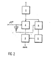
- Fig. 2 shows in a block diagram how this known technique is applied.
- the high-frequency signal is rectified, whereafter the responder pulse is supplied to two parallel gates, namely, a responder pulse gate 2 and an interference gate 4.
- the responder pulse gate 2 is opened by the time slot pulse p generated in the transmitter section. When no responder pulse is expected, the time slot pulse is low. The responder pulse gate 2 is then closed.
- interference gate 4 is simultaneously switched open. Spurious signals can then be detected in interference detector 5, which subsequently blocks the responder pulse detector 3, if indeed a spurious signal is detected. During the reception of interference, therefore, this installation is completely blocked, and no alarm can be given.
- the invention is predicated on the fact that the responder pulse itself occupies a limited period of time of the entire frequency sweep period, and that after the time interval of the first responder pulse a, generally longer, time interval follows in which a responder pulse is certain not to occur.
- Fig. 3 shows a block diagram of an example of a circuit according to the invention forming part of an electromagnetic detection system.
- Figs. 4 and 5 show associated time diagrams.
- Fig. 3 shows diagrammatically the detection means of an electromagnetic detection system according to the invention.
- a device 31 Connected to an aerial 30 is a device 31 which is capable of receiving signals caused by the presence of a responder.
- the aerial 30 may be the same aerial as is used for generating the interrogation field or a separate aerial, depending on the fact whether the system works by the absorption principle or by the transmission principle.
- the apparatus 31 may comprise means for eliminating so-called out- band signals, i.e., spurious signals having a frequency outside the sweep frequency band.
- the apparatus 31 does not by itself form part of the invention, and will therefore not be described in any detail herein.
- the output of apparatus 31 is connected to an amplifier 32 with automatic gain control (AGC).
- AGC automatic gain control
- the output signals of the amplifier consist of noise and of signals resulting from signals received by the detection means and having a frequency within the sweep frequency band.
- the output signals from amplifier 32 are supplied to a discriminator filter device comprising two channels and serving to take so-called in-band spurious signals into account in actuating an alarm device.
- the discriminator filter device comprise a low-frequency channel including a low-pass filter 33, an amplifier 34 and a diode detector or rectifier 35.
- the low-frequency channel can process signals having a frequency between f L and f H , i.e., signals having a frequency corresponding to the frequency of responder pulse signals.
- the cut-off frequency of the low-pass filter 33 may be at 6 kHz.
- the discriminator filter device further comprises a high-frequency channel including a high-pass filter 36, an (adjustable) amplifier 37 and a diode detector or rectifier 38.
- the high-frequency channel can process output signals from amplifier 32 having frequencies higher than f H .
- the high-frequency channel can process (spurious) signals having frequencies of between 6 kHz and, e.g., 25 kHz.
- the output of the low-frequency channel is connected to a positive input of a summator 39, and the output of the high-frequency channel is connected to a negative input of summator 39.
- the output of summator 39 is in turn connected to an integrator 40.
- an output signal from the high-frequency channel causes a decrease of the output signal from the integrator, whereas an output signal from the low-frequency channel causes an increase of the output signal from the integrator.
- an (adjustable) AGC-detector 41 which controls the gain of the amplifier 32 in such a manner that the tops of the signal pulses at the output of amplifier 34 keep a substantially constant level.
- Summator 39 is arranged so that the negative input is more sensitive than the positive input, so that, at rest, when the discriminator filter device only passes broad-band noise (2-25 kHz) the output signal from integrator 40 is low and no alarm signal can be given.
- circuitry 12 will be elucidated with reference to Figs. 4 and 5.
- a pulse detector 8 connected to the outpt of amplifier 34 in the responder pulse channel forms a pulse P, so long as the (negative) top of a responder pulse R (see Fig. 4, line 1) exceeds a pre-determined detection threshold D (line 2) recorded in pulse detector 8.
- This pulse causes a timer pulse Pt (line 4) to start at the leading edge in a delay circuit 9 connected to pulse detector 8.
- the trailing edge of pulse Pt activates a time slot generator 10, which generates a time slot pulse Pe (line 5).
- the output of the time slot generator is connected to an input of an AND gating device 11.
- the other input of the AND gating device 11 is connected to the output of pulse detector 8. Furthermore, the output of gating device 11 is connected to a negative input 14, which is separate in this example of the summator.
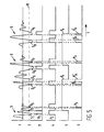
- Fig. 4 shows that responder pulses R do not give rise to blocking pulses in gate 11 (see line 6), while Fig. 5 shows that (pulse) interference S of an irregular pattern does cause blocking pulses Pb in gate 11, so that alarm signals are blocked.
- Fig. 5 shows similarly to Fig. 4 signals occurring in the blanking circuitry, but now for the case that a spurious pulse signal S appears at the output of amplifier 34 and hence at the input of pulse detector 8.
- a spurious pulse signal S appears at the output of amplifier 34 and hence at the input of pulse detector 8.
- a responder pulse R such a signal will generally comprise a number of closely-spaced successive peaks, which with a correct selection of the detection threshold of pulse detector 8 will exceed this threshold, as indicated in Fig. 5 for the negative peaks S,-S 9 .
- peak S gives rise to an output pulse P, of the pulse detector 8, and the output pulse P, in turn causes a timer pulse Pt, which again results in a time slot pulse Pe.
- Peak S 2 falls within the duration of pulse Pt and thus has no effect.
- Peak S 3 falls within time slot pulse Pe and is thus, just as peaks S 4 , 5 5 , S,, S a and Sg (in part), passed by gate 11 in the form of pulses Pb, Pb' and Pb" (see line 6 of Fig. 5).
- the duration of pulses Pt i.e., the delay caused by delay circuitry 9, may be, e.g., 0.25 msec. This delay should be chosen so that any width of a responder pulse R which occurs in practice at the level of detection threshold D leads to a pulse P, which lasts no longer than Pt.
- the time slot pulse Pe may, in a practical apparatus, last e.g. 2 msec.
- the pulse detector may be arranged to react positive peaks exceeding a positive pre-determined threshold.
- pulse detector 8 could be combined with the delay device 9.
- summator 39 and integrator 40 could be combined to form a single integrator with a positive and a negative input and an additional negative input 14 or a reset input.
- the normal negative input of the summator is more sensitive than the positive input, a good suppression of spurious signals can in certain situations also be obtained if the output of gate 11 is connected to the (normal) negative input of the summator.
- the blanking circuit 12 can even be applied fully independently of the way in which signals in the frequency band associated with the frequency band of the responder pulses are obtained and further processed separately from the signals outside that band.
Description
- This invention relates to an electromagnetic detection system which, by means of at least one transmission aerial coil, generates a sweeping- frequency interrogation field in a detection zone, which field can be disturbed by the presence in said zone of a responder equipped with a tuned circuit, there being provided detection means for detecting such disturbance and activating an alarm device.
- Systems of this kind are known in various embodiments. The disturbance takes place selectively, i.e. at a pre-determined frequency, or in a pre-determined frequency range, because the responder comprises a tuned circuit. As is known, the field disturbance by a responder can be detected both by detecting the results of energy absorbption by a responder at the transmission side of the system, and by detecting the signals sent out by a responder in reaction to the interrogation field, by means of a receiver. By the selective absorption, the energy contents of the transmission circuit are modulated, which modulation can be detected by means of an envelope detector, which may consist of a simple diode. This envelope detector produces a pulse in the form of the resonance curve of the tuned circuit of the responder. This form is known and the detected pulse can therefore be compared to the known form. Similarly, when using a receiver receiving signals sent out by a responder, a pulse can be detected which has the form of the resonance curve.
- The form of the detected pulse is also found back in the frequency spectrum contained in the pulse.
- Investigations have shown that a given sweep rate and Q factor of the responder circuit are associated with a most characteristic frequency range of the spectrum of the responder pulse.
- This frequency range has a lowest frequency fL and a highest frequency fH. There are virtually no signal components above fH. In a practical system fL can be 2 kHz and
f H 6 kHz. - Interference, for example, noise from the system's own transceiver circuit, external radio signals, or crackling (caused by passing metal objects, such as perambulators) have a rather flat spectral distribution.
- As the receiver has a larger bandwidth than the responder pulse, e.g., a bandwidth of up to 25 kHz, frequencies of the spurious signals between 6 and 25 kHz are therefore also received.
- It can then be concluded from the ratio between received frequency components within the frequency band of the responder pulse, 2 to 6 kHz, and those outside the frequency band whether the signal received is a spurious signal or a responder pulse.
- This operational principle is known from Dutch patent application No. 8202951.
- Although this principle works very well in practice, there is yet a situation in which a false alarm can be caused, namely, if there are spurious signals whose frequency components are mainly behween fL and f". Such spurious signals may in practice have the following cause.
- In an anti-shop-lifting system in which the above operational principle is applied, the aerial coil may be placed in a, generally chromium- plated metallic tube which is electrically interrupted at one location. This tube has both a mechanical carrier function and a screening function for electrical fields. As the tube is not hidden, it is possible to make electrical contact with the tube from the outside. By inductive coupling with the aerial coil, the tube carries a high-frequency voltage. Now, if the tube is touched by metallic articles, human hands, a current will start to flow in it.
- The making and breaking of such a touching contact causes crackling interference. In the case of contact with metallic articles, this crackling interference is of the broad-band type, so that owing to the above operational principle no false alarm is caused. If, however, contact is made with the human skin, a crackling interference is caused which is not of the broad-band type, but only causes frequency components of up to about 6 kHz in the receiver. This narrow-bandedness is caused by the fact that the skin is a relatively poor conductor, owing to which the conductivity of the junction from the tube to the skin is proportional to the contacting area. This area can only be varied at a limited rate, as a consequence of which the conductivity from the tube to the skin can only be changed slowly and continuously as well.
- Consequently, the high-frequency impedance of the aerial is only varied slowly and continuously, so that the crackling interference products which in fact are formed by the modulation of the high-frequency transmission signal (=carrier wave) as a result of the impedance variation, only have a limited bandwidth as well. The result is that touching the screening tube only causes crackling interference in the frequency range of up to 6 kHz, i.e., only in the responder pulse band, and so may cause a false alarm.
- It is an object of the invention to provide an electromagnetic detection system in which the described form of false alarm, that is to say, false alarm as a result of a spurious signal having a frequency spectrum substantially in the same frequency range as the frequency spectrum of a responder signal, is suppressed.
- For this purpose, according to the invention, an electromagnetic detection system of the kind described is characterized in that the detection means comprise a channel for processing signals in a frequency band corresponding to the frequency band of a signal caused by a responder, and that a blanking circuit is connected to said channel for detecting the occurrence in said channel of signals exceeding a pre-determined threshold value, and, after detecting a first signal exceeding said threshold value, in response to one or more further signals exceeding said pre- determined threshold value, producing a blanking signal for a pre-determined time interval to prevent activation of said alarm device.
- The invention will be described in more detail hereinafter with reference to the accompanying drawings.
- Fig. 1 illustrates the relationship between a sweeping field frequency and the occurrence of responder pulses;
- Fig. 2 shows an example of a known detection system comprising means for preventing false alarm;
- Fig. 3 shows an example of a system according to the invention; and
- Figs. 4 and 5 illustrate some waveforms occurring in the absence and in the presence of spurious signals.
- Fig. 1 shows, in line A, the variation of the frequency of the interrogation field of a sweeping- frequency detection system. The frequency f of the interrogation field swings periodically relative to a frequency fr. The frequency f may vary sinusoidally, as shown, but may also vary otherwise, e.g., in sawtooth form. The frequency fr corresponds to the resonant frequency of the responder. The resonant frequency of the responder may be the average of the highest and lowest field frequency, as shown, but this is not strictly necessary.
- Line B of Fig. 1 shows the moments when responder pulses occur. The responder pulses occur at every moment when the field frequency f passes the resonant frequency fr, provided indeed a responder is present in the interrogation field. Accordingly, in each sweep period of the field frequency a responder pulse occurs twice, and this at pre-determined points of time.
- In the example shown, the responder pulses occur at intervals equal to half the period of the sweep frequency. In practice, as usual, a certain tolerance should be taken into account.
- Starting from the fact that-in a detection system with a periodically sweeping field frequency-responder pulses can only occur at pre- determined points of time and at a fixed rhythm, it has already been tried in the past to suppress certain kinds of false alarm.
- For this purpose, as described for example in US patent 3,868,669, use is made of time slot pulses derived from the frequency sweep of the interrogation field.
- Line C in Fig. 1 shows these time slot pulses. The time slot pulses are generated in the transmission section of the detection system and are high at the moments when responder pulses can be expected. The time slot pulses open a responder pulse gating circuit at the times when the time slot pulses are high. This gating circuit then passes the responder pulses to the responder pulse detector.
- Fig. 2 shows in a block diagram how this known technique is applied.
- In a receiver/
detector 1, the high-frequency signal is rectified, whereafter the responder pulse is supplied to two parallel gates, namely, aresponder pulse gate 2 and aninterference gate 4. At the time when a responder pulse is expected, theresponder pulse gate 2 is opened by the time slot pulse p generated in the transmitter section. When no responder pulse is expected, the time slot pulse is low. Theresponder pulse gate 2 is then closed. - Via an
inverter 6,interference gate 4 is simultaneously switched open. Spurious signals can then be detected ininterference detector 5, which subsequently blocks theresponder pulse detector 3, if indeed a spurious signal is detected. During the reception of interference, therefore, this installation is completely blocked, and no alarm can be given. The invention is predicated on the fact that the responder pulse itself occupies a limited period of time of the entire frequency sweep period, and that after the time interval of the first responder pulse a, generally longer, time interval follows in which a responder pulse is certain not to occur. - If, during this second time interval, pulses are detected all the same, such pulses originate with certainty from spurious signals, and the signalling should be blocked.
- Fig. 3 shows a block diagram of an example of a circuit according to the invention forming part of an electromagnetic detection system. Figs. 4 and 5 show associated time diagrams.
- Fig. 3 shows diagrammatically the detection means of an electromagnetic detection system according to the invention. Connected to an aerial 30 is a
device 31 which is capable of receiving signals caused by the presence of a responder. The aerial 30 may be the same aerial as is used for generating the interrogation field or a separate aerial, depending on the fact whether the system works by the absorption principle or by the transmission principle. - In both cases the invention is applicable.
- As described, for example, in the above Dutch patent application 8202951, the
apparatus 31 may comprise means for eliminating so-called out- band signals, i.e., spurious signals having a frequency outside the sweep frequency band. - The
apparatus 31 does not by itself form part of the invention, and will therefore not be described in any detail herein. - The output of
apparatus 31 is connected to anamplifier 32 with automatic gain control (AGC). The output signals of the amplifier consist of noise and of signals resulting from signals received by the detection means and having a frequency within the sweep frequency band. - In a manner similarto hhat described in Netherlands patent application 8202951, the output signals from
amplifier 32 are supplied to a discriminator filter device comprising two channels and serving to take so-called in-band spurious signals into account in actuating an alarm device. - The discriminator filter device comprise a low-frequency channel including a low-
pass filter 33, anamplifier 34 and a diode detector orrectifier 35. The low-frequency channel can process signals having a frequency between fL and fH, i.e., signals having a frequency corresponding to the frequency of responder pulse signals. In a practical embodiment, the cut-off frequency of the low-pass filter 33 may be at 6 kHz. - The discriminator filter device further comprises a high-frequency channel including a high-
pass filter 36, an (adjustable)amplifier 37 and a diode detector orrectifier 38. The high-frequency channel can process output signals fromamplifier 32 having frequencies higher than fH. In a practical embodiment, the high-frequency channel can process (spurious) signals having frequencies of between 6 kHz and, e.g., 25 kHz. - The output of the low-frequency channel is connected to a positive input of a
summator 39, and the output of the high-frequency channel is connected to a negative input ofsummator 39. The output ofsummator 39 is in turn connected to an integrator 40. - Accordingly, an output signal from the high-frequency channel causes a decrease of the output signal from the integrator, whereas an output signal from the low-frequency channel causes an increase of the output signal from the integrator.
- Furthermore, connected to the output of
amplifier 34 of the low-frequency channel is an (adjustable) AGC-detector 41, which controls the gain of theamplifier 32 in such a manner that the tops of the signal pulses at the output ofamplifier 34 keep a substantially constant level. -
Summator 39 is arranged so that the negative input is more sensitive than the positive input, so that, at rest, when the discriminator filter device only passes broad-band noise (2-25 kHz) the output signal from integrator 40 is low and no alarm signal can be given. - When a responder pulse is received, then as a result of the operation of the AGC, which keeps the top signal level, i.e., the top of the responder pulse, at the output of
amplifier 34 constant, the gain of the precedingamplifier 32 will decrease and hence the noise in the interference channel (i.e., the high-frequency channel) will decrease. As the responder pulse contains no frequency components in excess of 6 kHz, the integrator will no longer be controlled downwards, but will be controlled upwards by the output ofdetector 35. At a given moment, the output voltage of integrator 40 will exceed a detection threshold recorded in acomparator 42 connected to the integrator, and as a result actuate analarming circuit 43. - It will now be clear that a spurious signal containing just frequency components in the range of 2-6 kHz will also cause an alarm. To suppress such an alarm, a blanking
circuit 12 is added. - The operation of
circuitry 12 will be elucidated with reference to Figs. 4 and 5. A pulse detector 8 connected to the outpt ofamplifier 34 in the responder pulse channel forms a pulse P, so long as the (negative) top of a responder pulse R (see Fig. 4, line 1) exceeds a pre-determined detection threshold D (line 2) recorded in pulse detector 8. This pulse causes a timer pulse Pt (line 4) to start at the leading edge in adelay circuit 9 connected to pulse detector 8. The trailing edge of pulse Pt activates atime slot generator 10, which generates a time slot pulse Pe (line 5). - The output of the time slot generator is connected to an input of an AND
gating device 11. The other input of the AND gatingdevice 11 is connected to the output of pulse detector 8. Furthermore, the output of gatingdevice 11 is connected to a negative input 14, which is separate in this example of the summator. - So long as the time slot pulse Pe is high, the
gating device 11 is in the open condition, so that the pulses from pulse detector 8 are passed to the summator 13. A pulse which passes gate 11 (blocking pulse Pb, seeline 6, Fig. 5), does cause the integrator output to be immediately decreased to zero, independently of the other input voltages of a summator and thus blocking alarm signals. - Fig. 4 shows that responder pulses R do not give rise to blocking pulses in gate 11 (see line 6), while Fig. 5 shows that (pulse) interference S of an irregular pattern does cause blocking pulses Pb in
gate 11, so that alarm signals are blocked. - Fig. 5 shows similarly to Fig. 4 signals occurring in the blanking circuitry, but now for the case that a spurious pulse signal S appears at the output of
amplifier 34 and hence at the input of pulse detector 8. Unlike a responder pulse R, such a signal will generally comprise a number of closely-spaced successive peaks, which with a correct selection of the detection threshold of pulse detector 8 will exceed this threshold, as indicated in Fig. 5 for the negative peaks S,-S9. Similarly to a responder pulse R, peak S, gives rise to an output pulse P, of the pulse detector 8, and the output pulse P, in turn causes a timer pulse Pt, which again results in a time slot pulse Pe. Peak S2 falls within the duration of pulse Pt and thus has no effect. Peak S3, however, falls within time slot pulse Pe and is thus, just as peaks S4, 55, S,, Sa and Sg (in part), passed bygate 11 in the form of pulses Pb, Pb' and Pb" (seeline 6 of Fig. 5). - However, if in addition to this (pulse) interference S a responder signal is received, and this signal is stronger than the interference, the AGC operation will attenuate the spurious signal, so that the interference no longer produces pulses in pulse detector 8. There is, accordingly, no blocking, and an alarm does go off (and rightly so).
- This shows that the blanking circuit does not cause absolute blocking, as is the case with other known (shop-lifting) detection systems, but causes a decrease in detection sensitivity depending on the level of the spurious signal.
- In this way, a detection system incorporating the above operational principles functions in an optimal manner under all conditions.
- It is noted that, in practice, the duration of pulses Pt, i.e., the delay caused by
delay circuitry 9, may be, e.g., 0.25 msec. This delay should be chosen so that any width of a responder pulse R which occurs in practice at the level of detection threshold D leads to a pulse P, which lasts no longer than Pt. - The time slot pulse Pe may, in a practical apparatus, last e.g. 2 msec.
- It is further noted that, after the foregoing, various modifications will readily occur to those skilled in the art. Thus the pulse detector may be arranged to react positive peaks exceeding a positive pre-determined threshold.
- Furthermore, the pulse detector 8 could be combined with the
delay device 9. Also,summator 39 and integrator 40 could be combined to form a single integrator with a positive and a negative input and an additional negative input 14 or a reset input. As the normal negative input of the summator is more sensitive than the positive input, a good suppression of spurious signals can in certain situations also be obtained if the output ofgate 11 is connected to the (normal) negative input of the summator. - The blanking
circuit 12 can even be applied fully independently of the way in which signals in the frequency band associated with the frequency band of the responder pulses are obtained and further processed separately from the signals outside that band. - These and similar modifications are considered to fall within the scope of the invention.
Claims (12)
Applications Claiming Priority (2)
| Application Number | Priority Date | Filing Date | Title |
|---|---|---|---|
| NL8600738A NL8600738A (en) | 1986-03-24 | 1986-03-24 | Suppression of false alarms due to touch. |
| NL8600738 | 1986-03-24 |
Publications (2)
| Publication Number | Publication Date |
|---|---|
| EP0242901A1 EP0242901A1 (en) | 1987-10-28 |
| EP0242901B1 true EP0242901B1 (en) | 1990-12-12 |
Family
ID=19847757
Family Applications (1)
| Application Number | Title | Priority Date | Filing Date |
|---|---|---|---|
| EP19870200534 Expired - Lifetime EP0242901B1 (en) | 1986-03-24 | 1987-03-24 | An electromagnetic detection system with improved false-alarm suppression |
Country Status (3)
| Country | Link |
|---|---|
| EP (1) | EP0242901B1 (en) |
| DE (1) | DE3766644D1 (en) |
| NL (1) | NL8600738A (en) |
Cited By (1)
| Publication number | Priority date | Publication date | Assignee | Title |
|---|---|---|---|---|
| US8337071B2 (en) | 2005-12-21 | 2012-12-25 | Cree, Inc. | Lighting device |
Families Citing this family (2)
| Publication number | Priority date | Publication date | Assignee | Title |
|---|---|---|---|---|
| GB8828896D0 (en) * | 1988-12-10 | 1989-01-18 | Higgs R R | Anti-tamper device |
| FR2704960A1 (en) * | 1993-05-03 | 1994-11-10 | Diet Jean Paul | Device for detecting the passage of labels |
Family Cites Families (5)
| Publication number | Priority date | Publication date | Assignee | Title |
|---|---|---|---|---|
| US3110007A (en) * | 1959-10-14 | 1963-11-05 | Gen Signal Corp | Ultrasonic vehicle detector |
| NL161904C (en) * | 1973-04-13 | Knogo Corp | THEFT DETECTION SYSTEM. | |
| US4117466A (en) * | 1977-03-14 | 1978-09-26 | Lichtblau G J | Beat frequency interference rejection circuit |
| US4429302A (en) * | 1981-10-08 | 1984-01-31 | I. D. Engineering, Inc. | Electronic security system with noise rejection |
| NL8202951A (en) * | 1982-07-21 | 1984-02-16 | Nedap Nv | ABSORPTION DETECTION SYSTEM. |
-
1986
- 1986-03-24 NL NL8600738A patent/NL8600738A/en not_active Application Discontinuation
-
1987
- 1987-03-24 DE DE8787200534T patent/DE3766644D1/en not_active Expired - Fee Related
- 1987-03-24 EP EP19870200534 patent/EP0242901B1/en not_active Expired - Lifetime
Cited By (1)
| Publication number | Priority date | Publication date | Assignee | Title |
|---|---|---|---|---|
| US8337071B2 (en) | 2005-12-21 | 2012-12-25 | Cree, Inc. | Lighting device |
Also Published As
| Publication number | Publication date |
|---|---|
| DE3766644D1 (en) | 1991-01-24 |
| NL8600738A (en) | 1987-10-16 |
| EP0242901A1 (en) | 1987-10-28 |
Similar Documents
| Publication | Publication Date | Title |
|---|---|---|
| US5463376A (en) | System and method for synchronizing a receiver of an electronic article surveillance system and a transmitter thereof | |
| EP0226402B1 (en) | Wireless synchronization system for electronic article surveillance system | |
| US5068663A (en) | Motor vehicle radar detector including amplitude detection | |
| EP0994364B1 (en) | Procedure for reading the data stored in a transponder and a transponder system for the execution of the procedure | |
| US5349463A (en) | Optical radio repeater with signal quality detection | |
| EP1225455A3 (en) | Radar apparatus with RFI suppression | |
| EP0084400B1 (en) | Detection system | |
| GB2167923A (en) | Spread spectrum communications system | |
| DK162864B (en) | VARIABLE FREQUENCY ELECTRONIC MONITORING SYSTEM | |
| US4686517A (en) | Field disturbance detection system | |
| AU656426B2 (en) | Negative feedback control loop acquisition aid | |
| EP0242901B1 (en) | An electromagnetic detection system with improved false-alarm suppression | |
| US5021791A (en) | Radar systems | |
| US4371981A (en) | Spectral squelch | |
| US4117466A (en) | Beat frequency interference rejection circuit | |
| GB1537546A (en) | Anti-intrusion miniradar | |
| US4445223A (en) | Apparatus and method for determining the presence and frequency of a periodic signal | |
| CA1281379C (en) | Emergency locating transmitter and receiver system | |
| US3624507A (en) | Communication system of a cue signal or signals | |
| CA1225715A (en) | Field disturbance detection system | |
| US4206410A (en) | Automatic frequency control system for single sideband signal receiver | |
| WO1985000256A1 (en) | Squelch circuit | |
| US4295221A (en) | Method and apparatus at one-way or two-way information link to effect interference suppression | |
| US4680772A (en) | Digital signal repeater including means for controlling a transmitter | |
| US5969611A (en) | Apparatus for the surveillance of an electronic security element in an interrogation zone |
Legal Events
| Date | Code | Title | Description |
|---|---|---|---|
| PUAI | Public reference made under article 153(3) epc to a published international application that has entered the european phase |
Free format text: ORIGINAL CODE: 0009012 |
|
| AK | Designated contracting states |
Kind code of ref document: A1 Designated state(s): BE DE FR GB NL |
|
| 17P | Request for examination filed |
Effective date: 19871222 |
|
| 17Q | First examination report despatched |
Effective date: 19900122 |
|
| GRAA | (expected) grant |
Free format text: ORIGINAL CODE: 0009210 |
|
| AK | Designated contracting states |
Kind code of ref document: B1 Designated state(s): BE DE FR GB NL |
|
| REF | Corresponds to: |
Ref document number: 3766644 Country of ref document: DE Date of ref document: 19910124 |
|
| ET | Fr: translation filed | ||
| PLBE | No opposition filed within time limit |
Free format text: ORIGINAL CODE: 0009261 |
|
| STAA | Information on the status of an ep patent application or granted ep patent |
Free format text: STATUS: NO OPPOSITION FILED WITHIN TIME LIMIT |
|
| 26N | No opposition filed | ||
| PGFP | Annual fee paid to national office [announced via postgrant information from national office to epo] |
Ref country code: NL Payment date: 19940331 Year of fee payment: 8 |
|
| PGFP | Annual fee paid to national office [announced via postgrant information from national office to epo] |
Ref country code: FR Payment date: 19950314 Year of fee payment: 9 |
|
| PGFP | Annual fee paid to national office [announced via postgrant information from national office to epo] |
Ref country code: GB Payment date: 19950315 Year of fee payment: 9 |
|
| PGFP | Annual fee paid to national office [announced via postgrant information from national office to epo] |
Ref country code: BE Payment date: 19950328 Year of fee payment: 9 |
|
| PGFP | Annual fee paid to national office [announced via postgrant information from national office to epo] |
Ref country code: DE Payment date: 19950412 Year of fee payment: 9 |
|
| PG25 | Lapsed in a contracting state [announced via postgrant information from national office to epo] |
Ref country code: NL Effective date: 19951001 |
|
| NLV4 | Nl: lapsed or anulled due to non-payment of the annual fee |
Effective date: 19951001 |
|
| PG25 | Lapsed in a contracting state [announced via postgrant information from national office to epo] |
Ref country code: GB Effective date: 19960324 |
|
| PG25 | Lapsed in a contracting state [announced via postgrant information from national office to epo] |
Ref country code: BE Effective date: 19960331 |
|
| BERE | Be: lapsed |
Owner name: NEDERLANDSCHE APPARATENFABRIEK NEDAP N.V. Effective date: 19960331 |
|
| GBPC | Gb: european patent ceased through non-payment of renewal fee |
Effective date: 19960324 |
|
| PG25 | Lapsed in a contracting state [announced via postgrant information from national office to epo] |
Ref country code: FR Effective date: 19961129 |
|
| PG25 | Lapsed in a contracting state [announced via postgrant information from national office to epo] |
Ref country code: DE Effective date: 19961203 |
|
| REG | Reference to a national code |
Ref country code: FR Ref legal event code: ST |