EP0242632B1 - Gerät und Verfahren zum rationellen Linienzeichnen - Google Patents
Gerät und Verfahren zum rationellen Linienzeichnen Download PDFInfo
- Publication number
- EP0242632B1 EP0242632B1 EP87104531A EP87104531A EP0242632B1 EP 0242632 B1 EP0242632 B1 EP 0242632B1 EP 87104531 A EP87104531 A EP 87104531A EP 87104531 A EP87104531 A EP 87104531A EP 0242632 B1 EP0242632 B1 EP 0242632B1
- Authority
- EP
- European Patent Office
- Prior art keywords
- plotting
- plotter
- bin
- instructions
- color
- Prior art date
- Legal status (The legal status is an assumption and is not a legal conclusion. Google has not performed a legal analysis and makes no representation as to the accuracy of the status listed.)
- Expired - Lifetime
Links
Images


Classifications
-
- G—PHYSICS
- G06—COMPUTING OR CALCULATING; COUNTING
- G06K—GRAPHICAL DATA READING; PRESENTATION OF DATA; RECORD CARRIERS; HANDLING RECORD CARRIERS
- G06K15/00—Arrangements for producing a permanent visual presentation of the output data, e.g. computer output printers
- G06K15/22—Arrangements for producing a permanent visual presentation of the output data, e.g. computer output printers using plotters
- G06K15/225—Arrangements for producing a permanent visual presentation of the output data, e.g. computer output printers using plotters using optical plotters
Definitions
- Modern high speed plotters operate under computer control to plot variously colored vectors onto sheets of recording medium.
- the host computer provides to the plotter a long string of vectors to be plotted and also provides commands to raise or lower the pen carriage and to select a pen of a certain color from among a set of available pens.
- the available pens may be carried on the pen carriage, as in the Calcomp Co. model 965 plotter, or may be stored in an accessible pen carousel as in the Hewlett-Packard Co. model HP 7585 plotter which is disclosed in Hewlett-Packard Technical data brochure "A complete family of HP drafting plotters "Technical Data, August 1985.
- Plotters for plotting coloured lines on a sheet in response to commands from a computer are also known from DE-A 27 55 586.
- the present inventors have discovered that a large portion of the time spent plotting is actually taken up by pen changes rather than by vector plotting.
- the applicants have determined that a typical pen change takes on the order of one second to complete while a typical vector can be plotted in approximately ten milliseconds.
- the inventors have further noted that plotting efficiency decreases dramatically as pen changes occur more frequently than once for each approximately one thousand vector plots.
- a preferred embodiment of the present invention operates in accordance with the following principles.
- a plotter continuously performs a dynamic sort on incoming vectors and stores the vectors by color in linked memory locations. At the same time that the incoming dynamic sort is occuring, the plotter determines the color having the most stored vectors and plots all of the stored vectors of that color before selecting the next color to be plotted. Thus, the plotter simultaneously sorts and plots the incoming vectors so that the number of pen changes is reduced and plotting efficiency is increased without requiring an unproductive sorting period before actual plotting begins.
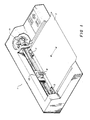
- Figure 1 shows a plotter which is constructed in accordance with the preferred embodiment of the present invention.
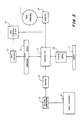
- Figure 2 is a block diagram of the plotter shown in Figure 1.
- Figure 3 is a pictorial representation of the continuous dynamic sort performed by the plotter shown in Figure 1.
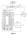
- Figure 4 is a block diagram of the sorter shown in Figure 2.
- Figure 5 shows a portion of the memory shown in Figure 4.
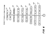
- Figures 6-8 are flow charts of various steps performed during plotting by the plotter shown in Figure 1.
- Figure 1 shows a plotter 1 which is constructed in accordance with the preferred embodiment of the present invention.
- a sheet 3 may be moved in a forward or reverse X-direction by grit wheel/pinch wheel pairs 5, 7 while a pen carriage 13 moves a pen 9 in a Y-direction.
- a pen carousel 11 contains up to eight pens which may be selected by the carriage 13 in a pen change operation.
- Figure 2 is a block diagram of the plotter 1 shown in Figure 1.
- a controller 21 actuates a lifter 27 and a Y-axis servo 25 to raise and lower the carriage 13 and to move the carriage 13 back and forth across the sheet 3.
- the controller 21 also activates a rotater 29 to rotate the carousel 11 as needed to allow the carriage 13 to select a particular pen.
- a vector generator 31 receives commands from a host computer 33 and generates vectors for use by the controller 21 in plotting on the sheet 3.
- the elements 5-31 of the plotter 1 are well known and may comprise, e.g., elements used in the Hewlett-Packard Company model HP 7585 plotter.
- a host computer 33 such as a Hewlett-Packard Company model HP 3000 computer using DSG-3000 software, transmits commands in a graphics language to the plotter 1.
- Typical of such languages is the Hewlett-Packard Company graphics language, HP-GL.
- HP-GL uses various commands including Pen Up (PU), Pen Down (PD), SELECT PEN n (SP-n) from among the eight pens A-H available in the carousel 11 and the command Plot Absolute (PA-XY) to move the carriage 11 to an X,Y position.
- the vector generator 31 receives these commands and generates a string of vectors and commands in the same manner as the vector generator of the Hewlett-Packard company model HP 7585 plotter.
- the vector generator 31 generates 40 bit vectors comprising 16 bits of X information and 16 bits of Y information followed by 7 zero bits and a one bit field indicating a pen up or down condition for the vector.
- the vector generator 31 intersperses SELECT PEN and other commands between vectors as necessary.
- the computer 33 could send the following string of commands to the plotter 1 in order to draw a red vector (pen A) from point X1,Y1 to point X2,Y2 and a black vector (pen B) from point X3,Y3 to point X4,Y4 on the sheet 3: SP-A PA-X1Y1 PD PA-X2Y2 SP-B PU PA-X3Y3 PD PA-X4Y4 Using the 40-bit vectors and the SELECT PEN command, the vector generator 31 would then generate the following string: SELECT PEN, A (X1),(Y1),(0),(U) (X2),(Y2),(0),(D) SELECT PEN, B (X3),(Y3),(0),(U) (Y4),(Y4),(0),(D) which would be sorted by the sorter 35 and would be used by the controller 21 to plot the vectors on the sheet 3.
- Figure 3 is a pictorial representation of the operation of the sorter 35.
- the sorter 35 operates continuously to perform a dynamic sort on the vectors generated by the vector generator 31 from the commands received from the host computer 33. No optimization or sorting by the computer 33 is necessary.
- the vector generator 31 generates vector strings separated by SELECT PEN commands which indicate that the desired color of the plotted vector is to change. Thus, the vectors between SELECT PEN commands are all of the same color.
- the output of the vector generator 31 may be characterized pictorially as a string of different colored vectors (A-H) with no interspersed commands.
- the sorter 35 stores the individual vectors in eight separate bins A-H depending on color and determines which bin to open to the controller 21.
- the sorter 35 may be viewed as a continuous flow device with vectors flowing in from the vector generator 31 at the same time that vectors flow out to the controller 21.
- the output stream of the sorter 35 will be interrupted until the controller 21 is ready for more vectors.
- the input stream into the sorter 35 is still active until buffer 51 is full.
- the input stream to the sorter 35 is interrupted until the controller 21 re-activates the output stream of the sorter 35.
- FIG. 4 is a block diagram of the sorter 35 which contains a ROM 43, a RAM 47 and a buffer 45.
- the one kilobyte ROM 43 contains progam information for use by the controller 21 in implementing the dynamic sort.
- the RAM 47 which may be from 2 to 32 kilobytes long as required, contains: a two byte wide buffer 51; free list pointers FLP 55 and FLE 53; registers OLDX 57, OLDY 59, INPEN 61, OUTPEN 63 and NEWPEN 65; head pointers HP-A 71 through HP-H 85 and tail pointers TP-A 91 through TP-H 105; and, color counters CC-A 111 through CC-H 125.
- Figure 5 shows the two byte wide buffer 51 in detail. Since the plotter 1 is capable of plotting in eight colors, A-H, the buffer 51 is capable of storing vectors in eight separate A-H bins 131-145. For the most efficient use of space within the buffer 51, the individual bins 131-145 each comprise linked lists with bin size determined by actual requirements. Each stored vector is stored in a six byte location. Within each location a two byte X field contains a vector X coordinate and a two byte Y field contains a vector Y coordinate. A 15-bit P field contains the address of the next location in the particular bin's linked list. Finally, a one bit V field indicates whether the stored vector is to be executed with the pen carriage 27 in either an up or a down position.
- Figures 6-8 are flow charts of initialization, insertion and removal routines performed by the plotter 1 during plotting.
- the plotter 1 performs standard power on sequences.
- steps 157-161 the plotter 1 initializes the pointers, counters and registers 57-125 of RAM 47.
- the plotter 1 creates a single free linked list within the buffer 51 in a well known manner. Starting at the top of the buffer 51, the X, Y and V fields of each three byte location are initialized. Each P field is then set to the address of the next three byte location as a link and the P field of the last location is set to NIL to indicate the end of the free list.
- steps 165, 167 the top free list pointer FLP 55 and the free list end pointer FLE 53 are set to contain the addresses of the first and last locations of the free list.
- Figure 7 is a flow chart of the steps performed by the plotter 1 during insertion of vectors into the buffer 51 and Figure 8 is a flow chart of the steps performed by the plotter 1 during removal of vectors from the buffer 51 and attendant plotting.
- Vectors flow into the buffer 51 from the vector generator 31 and computer 33 and concurrently flow out of the buffer 51 to the controller 21 for plotting.
- sorting, storing, selecting and plotting are performed concurrently with the steps of receiving and generating.
- the sorter 35 interrogates the vector generator 31 for input and determines if the next input is a SELECT PEN command. If the next input is a vector rather than a command, then the sorter 35 assumes that the vector is of the same color as the immediately preceding vector.
- the sorter 35 reads the X,Y information from the incoming vector and stores the information in the X and Y fields of the top free list location as indicated by the FLP 55.
- the V bit of the top location is set as indicated by the V bit of the incoming vector.
- the appropriate color counter CC is incremented for an updated total number of locations contained in the particular bin.
- the appropriate tail pointer TP is set to FLP to point to the current location as now being the last location in this particular bin.
- OLDX 57 and OLDY 59 are set to X and Y to store the most recent vector coordinates.
- FLP 55 is set to the next free list location address (from the P field of the current location) to indicate this next location as the new top free list location and the P field of the last location is set to NIL to indicate the end of that color bin. If all of the free list locations have been used, in steps 195, 197 the sorter 35 halts insertion and waits for removal and plotting to occur to create new free list locations.
- step 175 the input is a SELECT PEN command
- the sorter 35 determines that a new bin must be created or else a different existing bin must be added to.
- INPEN is set to the new color A-H indicated by the incoming SELECT PEN command. If the CC counter of the new color is zero then a new bin must be created and the new color head pointer HP is set to FLP to point to the top location of the newly created bin. If the incoming V bit indicates up, then normal flow starting at step 177 is entered. If the incoming V bit indicates down, then a potential problem condition exists since the carriage 27 should normally be moved in an up position from the carousel 11 to the starting position of the next vector to be plotted. In steps 211-219, an up vector is created and inserted before the incoming vector.
- Figure 8 shows the steps of the removal routine which are performed by the plotter 1 to remove vectors from the buffer 51 and to plot them onto the sheet 3. Since the routines of Figures 7 and 8 operate concurrently, the routine of Figure 8 may be started at any time that one or more vectors are resident in the buffer 51.
- step 251 the sorter 35 compares the eight color counters CC 111-125 to determine the particular color bin containing the most vectors to be plotted Once this determination is made, OUTPEN 63 and NEWPEN 65 are set to this color to indicate the color currently being plotted
- this particular color pen is fetched from the carousel 11 by the carriage 13.
- the head pointer HP of the particular color A-H is read to determine the top location within the buffer 51 of the desired color bin to be plotted from.
- the V bit of this top location is read to determine whether the carriage 13 should be raised or lowered and, in step 265, the carriage 13 is moved to the vector X,Y end position indicated by the top location.
- step 267 the location containing the vector just plotted is added to the end of the free list by setting to FLP the P field of the last free list location (as indicated by the free list end pointer FLE 53).
- step 269 the FLE 53 is set to the new end location.
- the appropriate color counter CC is decremented to indicate removal of a vector (and location) from the particular color bin. If this removal leaves the bin empty, then the sorter 35 again determines the fullest bin to plot from. If vectors still remain in the current color bin, then in step 275 the appropriate head pointer HP is advanced to the contents of the P field of the location just plotted and the new location is read in step 257.
- the inventors have analyzed typical plotter software applications and have found that the majority of business applications produce between 100 and 1000 vectors between pen changes. Most computer aided design or manufacturing applications produce only between one and 100 vectors between pen changes. Thus, in most such applications pen changes are made more frequently than every 1000 plotted vectors and, as a result, plotting is both inefficient and slow.
- the inventors performed a typical plot using the plotter 1 without the sorter 35 and measured the total plotting time as 18 minutes and 46 seconds. In contrast, the plotter 1 in conjunction with the sorter 35 made the same plot in 5 minutes, 30 seconds.
- the inventors also made the same plot using the plotter 1 without the sorter 35 but with the Graftek Company Optplot routine discussed above. Actual plotting with the Optplot routine required only 4 minutes, 30 seconds, but an initial non-plotting sort period of 2 minutes was required for a total plotting time of 6 minutes, 30 seconds.
Landscapes
- Engineering & Computer Science (AREA)
- General Engineering & Computer Science (AREA)
- Physics & Mathematics (AREA)
- General Physics & Mathematics (AREA)
- Theoretical Computer Science (AREA)
Claims (11)
- Zeichengerät (Plotter) (1) zum Zeichnen farbiger Linien auf ein Blatt abhängig von Befehlen von einem Host-Rechner (33) mit
einem Erzeuger (31) zum Empfangen der Befehle vom Host-Rechner (33) und zum Erzeugen einer Befehlszeichenfolge, welche die zu zeichnenden farbigen Linien angibt;
einem mit dem Erzeuger (31) gekoppelten Sortierer (35) zum Sortieren der Befehle nach Farben und zum Speichern der Befehle nach Farben in Magazinen (51) eines Speichers (47);
einer mit dem Speicher (47) gekoppelten Steuereinrichtung (21) zum Auswählen immer genau eines Magazins und zum Bereitstellen der in dem ausgewählten Magazin gespeicherten Befehle an einem Ausgang;
einer mit dem Ausgang der Steuereinrichtung gekoppelten Zeichenvorrichtung (13,23,25), die einen ausgewählten Stift trägt und abhängig von den Befehlen mit dem ausgewählten Stift auf das Blatt (3) zeichnet; und
bei dem die Steuereinrichtung (21) und die Zeichenvorrichtung (13,23,25) gleichzeitig mit dem Erzeuger (31) und dem Sortierer (35) arbeiten, so daß das Zeichengerät (1) während des Empfangs der Befehle vom Host-Rechner (33) die farbigen Linien zeichnen kann. - Zeichengerät nach Anspruch 1, dadurch gekennzeichnet, daß die vom Erzeuger (31) gebildete Befehlszeichenfolge Farbbezeichner, Zielkoordinaten und Stifthubindikatoren umfaßt.
- Zeichengerät nach Anspruch 2, dadurch gekennzeichnet, daß der Sortierer (35) Farbbezeichner empfangen und nachfolgend empfangene Zielkoordinaten und Stifthubindikatoren als Vektoren in einem besonderen,dem empfangenen Farbbezeichner zugeordneten Magazin speichern kann.
- Zeichengerät nach einem der Ansprüche 1 bis 3, dadurch gekennzeichnet, daß die Steuereinrichtung (21) das eine Magazin enthaltend die meisten Befehle auswählen kann.
- Zeichengerät nach einem der Ansprüche 1 bis 4, dadurch gekennzeichnet, daß die Steuereinrichtung (21) alle in dem ausgewählten Magazin gespeicherten Befehle zu der Zeichenvorrichtung (13,23,25) überträgt, bevor sie ein anderes Magazin auswählt.
- Zeichengerät nach einem der Ansprüche 1 bis 5, dadurch gekennzeichnet, daß der Speicher (47) einen Direktzugriffsspeicher (RAM)
und jedes Magazin eine Verknüpfungstabelle aufweisen. - Zeichengerät nach einem der Ansprüche 1 bis 6, dadurch gekennzeichnet, daß die Zeichenvorrichtung (13,23,25) den ausgewählten Stift aus einem oder mehreren verfügbaren Stiften auswählen kann, und daß die Zeichenvorrichtung (13,23,25) ferner den ausgewählten Stift heben, senken und relativ zum Einzelblatt (3) bewegen kann.
- Zeichengerät nach einem der Ansprüche 1 bis 7, dadurch gekennzeichnet, daß die verfügbaren Stifte in einem der Zeichenvorrichtung (13,23,25) zugänglichen Karussel (11) enthalten sind.
- Verfahren zum Zeichnen farbiger Linien auf ein Einzelblatt (3) abhängig von Befehlen von einem Host-Rechner (33) das folgende Verfahrensschritte aufweist:
Empfangen der Befehle vom Host-Rechner (33) und Erzeugen einer Befehlszeichenfolge, die die zu zeichnenden farbigen Linien angibt;
Sortieren der Befehle nach Farben;
Speichern der Befehle nach Farben in Magazinen (51) eines Speichers (47);
Auswählen eines Magazins;
Zeichnen auf ein Blatt (3) abhängig von Befehlen in den ausgewählten Magazinen;
wobei die Verfahrensschritte Sortieren, Speichern, Auswählen und Zeichnen gleichzeitig mit den Verfahrensschritten Empfangen und Erzeugen ausgeführt werden. - Verfahren nach Anspruch 9, dadurch gekennzeichnet, daß der Verfahrensschritt Auswählen das Auswählen des Magazins enthaltend die meisten Befehle umfaßt.
- Verfahren nach Anspruch 9 oder 10, dadurch gekennzeichnet, daß der Verfahrensschritt Zeichnen das Zeichnen auf ein Blatt (3) in Abhängigkeit von allen in dem ausgewählten Magazin enthaltenen Befehlen und die Wiederholung der Schritte Auswählen und Zeichnen umfaßt.
Applications Claiming Priority (2)
| Application Number | Priority Date | Filing Date | Title |
|---|---|---|---|
| US85421786A | 1986-04-21 | 1986-04-21 | |
| US854217 | 1986-04-21 |
Publications (3)
| Publication Number | Publication Date |
|---|---|
| EP0242632A2 EP0242632A2 (de) | 1987-10-28 |
| EP0242632A3 EP0242632A3 (en) | 1988-11-30 |
| EP0242632B1 true EP0242632B1 (de) | 1991-12-18 |
Family
ID=25318062
Family Applications (1)
| Application Number | Title | Priority Date | Filing Date |
|---|---|---|---|
| EP87104531A Expired - Lifetime EP0242632B1 (de) | 1986-04-21 | 1987-03-27 | Gerät und Verfahren zum rationellen Linienzeichnen |
Country Status (5)
| Country | Link |
|---|---|
| EP (1) | EP0242632B1 (de) |
| JP (1) | JPS62254232A (de) |
| CA (1) | CA1282180C (de) |
| DE (1) | DE3775255D1 (de) |
| ES (1) | ES2028814T3 (de) |
Family Cites Families (4)
| Publication number | Priority date | Publication date | Assignee | Title |
|---|---|---|---|---|
| US4135245A (en) * | 1977-01-04 | 1979-01-16 | Hewlett-Packard Company | Plotter with automatic pen-changer |
| GB2115565B (en) * | 1982-02-25 | 1985-09-11 | Hewlett Packard Co | Automatic pen sensor |
| JPS5957794A (ja) * | 1982-09-28 | 1984-04-03 | 株式会社東芝 | 自動製図装置 |
| JPS605332A (ja) * | 1983-06-24 | 1985-01-11 | Fujitsu Ltd | プロツタの色別情報処理方式 |
-
1987
- 1987-03-27 ES ES87104531T patent/ES2028814T3/es not_active Expired - Lifetime
- 1987-03-27 DE DE8787104531T patent/DE3775255D1/de not_active Expired - Lifetime
- 1987-03-27 EP EP87104531A patent/EP0242632B1/de not_active Expired - Lifetime
- 1987-04-15 CA CA000534799A patent/CA1282180C/en not_active Expired - Lifetime
- 1987-04-21 JP JP9960987A patent/JPS62254232A/ja active Pending
Non-Patent Citations (1)
| Title |
|---|
| Hewlett-Packard Technical data brochure "A complete family of HP drafting Plotters" Aug. 1985 * |
Also Published As
| Publication number | Publication date |
|---|---|
| EP0242632A3 (en) | 1988-11-30 |
| JPS62254232A (ja) | 1987-11-06 |
| CA1282180C (en) | 1991-03-26 |
| ES2028814T3 (es) | 1992-07-16 |
| DE3775255D1 (de) | 1992-01-30 |
| EP0242632A2 (de) | 1987-10-28 |
Similar Documents
| Publication | Publication Date | Title |
|---|---|---|
| US4853877A (en) | Apparatus and method for efficient plotting | |
| US4300206A (en) | Flexible text and image generator for a raster printer | |
| US4694405A (en) | Laser printer controller data alignment device | |
| US6687016B2 (en) | Method of utilizing variable data fields with a page description language | |
| KR100309078B1 (ko) | 프린터 | |
| JPS61101832A (ja) | ワ−ド・プロセツサ・システム | |
| US4470129A (en) | Page modification method in a printer subsystem of the partial page buffer composing type | |
| US4381553A (en) | Programmable printer controller with multiline buffering and overstrike feature | |
| EP0096407A1 (de) | Universelle Computer-Drucker Schnittstelle | |
| EP0954789A1 (de) | Bitmapdatenverarbeitungsarchitektur für einen rasterdrucker | |
| US4375079A (en) | Digital data display system | |
| GB2119982A (en) | Printer | |
| US5195176A (en) | Method and apparatus to enhance laser printer speed and functionality | |
| CA1172384A (en) | Method of controlling a printer in an interactive text processing system to print records from stored files of spatially related data | |
| EP0077892B1 (de) | Wortverarbeitendes System mit einem formatierenden bidirektionalen Drucker | |
| US4954966A (en) | Terminal with viewports, auxiliary device attachment, and host-terminal flan control | |
| EP0242632B1 (de) | Gerät und Verfahren zum rationellen Linienzeichnen | |
| EP0119396B1 (de) | Einrichtung und Verfahren zur Darstellung oder Anzeige von durch elektrische Signale dargestellte Daten | |
| US4765763A (en) | Method of confirming that a pattern to be printed is a high-density pattern and divisionally printing the pattern, and a dot printer which can print high-quality, high-density patterns | |
| EP0545648B1 (de) | Automatische Bestimmung der Druckersteuerungssprache | |
| EP0090802B1 (de) | Seitenmodifikationsverfahren in einem drucker-subsystem der mit teilseitenpuffern aufsetzenden art | |
| JPH0643142B2 (ja) | プリンタのスペ−ス処理装置 | |
| EP0026302B1 (de) | Verfahren zur Definition von Tabellierstops für textspeichernde Schreibmaschinen | |
| US5016190A (en) | Development of raster scan images from independent cells of imaged data | |
| US6775024B1 (en) | Method for selectively detecting and reading a character string |
Legal Events
| Date | Code | Title | Description |
|---|---|---|---|
| PUAI | Public reference made under article 153(3) epc to a published international application that has entered the european phase |
Free format text: ORIGINAL CODE: 0009012 |
|
| AK | Designated contracting states |
Kind code of ref document: A2 Designated state(s): DE ES FR GB IT |
|
| PUAL | Search report despatched |
Free format text: ORIGINAL CODE: 0009013 |
|
| AK | Designated contracting states |
Kind code of ref document: A3 Designated state(s): DE ES FR GB IT |
|
| 17P | Request for examination filed |
Effective date: 19890526 |
|
| 17Q | First examination report despatched |
Effective date: 19901112 |
|
| GRAA | (expected) grant |
Free format text: ORIGINAL CODE: 0009210 |
|
| AK | Designated contracting states |
Kind code of ref document: B1 Designated state(s): DE ES FR GB IT |
|
| REF | Corresponds to: |
Ref document number: 3775255 Country of ref document: DE Date of ref document: 19920130 |
|
| ET | Fr: translation filed | ||
| ITF | It: translation for a ep patent filed | ||
| REG | Reference to a national code |
Ref country code: ES Ref legal event code: FG2A Ref document number: 2028814 Country of ref document: ES Kind code of ref document: T3 |
|
| PLBE | No opposition filed within time limit |
Free format text: ORIGINAL CODE: 0009261 |
|
| STAA | Information on the status of an ep patent application or granted ep patent |
Free format text: STATUS: NO OPPOSITION FILED WITHIN TIME LIMIT |
|
| 26N | No opposition filed | ||
| PGFP | Annual fee paid to national office [announced via postgrant information from national office to epo] |
Ref country code: FR Payment date: 19950210 Year of fee payment: 9 |
|
| PGFP | Annual fee paid to national office [announced via postgrant information from national office to epo] |
Ref country code: DE Payment date: 19950227 Year of fee payment: 9 |
|
| PGFP | Annual fee paid to national office [announced via postgrant information from national office to epo] |
Ref country code: GB Payment date: 19950228 Year of fee payment: 9 |
|
| PGFP | Annual fee paid to national office [announced via postgrant information from national office to epo] |
Ref country code: ES Payment date: 19950309 Year of fee payment: 9 |
|
| PG25 | Lapsed in a contracting state [announced via postgrant information from national office to epo] |
Ref country code: GB Effective date: 19960327 |
|
| PG25 | Lapsed in a contracting state [announced via postgrant information from national office to epo] |
Ref country code: ES Free format text: LAPSE BECAUSE OF NON-PAYMENT OF DUE FEES Effective date: 19960328 |
|
| GBPC | Gb: european patent ceased through non-payment of renewal fee |
Effective date: 19960327 |
|
| PG25 | Lapsed in a contracting state [announced via postgrant information from national office to epo] |
Ref country code: FR Effective date: 19961129 |
|
| PG25 | Lapsed in a contracting state [announced via postgrant information from national office to epo] |
Ref country code: DE Effective date: 19961203 |
|
| REG | Reference to a national code |
Ref country code: FR Ref legal event code: ST |
|
| REG | Reference to a national code |
Ref country code: ES Ref legal event code: FD2A Effective date: 19990301 |
|
| PG25 | Lapsed in a contracting state [announced via postgrant information from national office to epo] |
Ref country code: IT Free format text: LAPSE BECAUSE OF NON-PAYMENT OF DUE FEES;WARNING: LAPSES OF ITALIAN PATENTS WITH EFFECTIVE DATE BEFORE 2007 MAY HAVE OCCURRED AT ANY TIME BEFORE 2007. THE CORRECT EFFECTIVE DATE MAY BE DIFFERENT FROM THE ONE RECORDED. Effective date: 20050327 |